Table of Contents
Advertisement
It is of vital importance, before attempting to operate
your engine, to read the general 'SAFETY
INSTRUCTIONS AND WARNINGS' section on
pages 2-6 of this booklet and to strictly adhere to the
advice contained therein.
Also, please study the entire contents of this
instruction manual, so as to familiarize yourself
with the controls and other features of the engine.
Keep these instructions in a safe place so that you
may readily refer to them whenever necessary.
It is suggested that any instructions supplied with
the aircraft, radio control equipment, etc., are
accessible for checking at the same time.
CONTENTS
RUNNING -IN, IDLING ADJUSTMENT CHART
2-6
7-8
9
10
11-14
15-16
17-19
ENGINE EXPLODED VIEWS & PARTS LIST
20-21
CARBURETOR EXPLODED VIEWS& PARTS LIST
22
23
24-26
1
27-30
31
32
33
34-35
36-37
38-39
40-41
42-43
44
Advertisement
Table of Contents

Related Manuals for O.S. engine max-65ax


Summary of Contents for O.S. engine max-65ax
-
Page 1: Table Of Contents
CONTENTS SAFETY INSTRUCTIONS AND WARNINGS RUNNING -IN, IDLING ADJUSTMENT CHART 27-30 ABOUT YOUR O.S. ENGINE MIXTURE CONTROL VALVE ADJUSTMENT ENGINE CONSTRUCTION, NOTES WHEN APPLYING AN ELECTTRIC STARTER REALIGNMENT OF MIXTURE CONTROL VALVE, SUBSEQUENT STARTINGPROCEDURE... -
Page 2: Safety Instructions And Warnings About Your O.s. Engine
As owner, you, alone, are responsible for the safe operation of your engine, so act with discretion and care at all times. If at some future date, your O.S. engine is acquired by another person, we would respectfully request that these instructions are also passed on to its new owner. - Page 3 NOTES This engine was designed for model If you remove the glowplug from the engine aircraft. Do not attempt to use it for any and check its condition by connecting the other purpose. battery leads to it, do not hold the plug with bare fingers.Use an appropriate tool or a Mount the engine in your model securely, folded piece of cloth.
-
Page 4: Engine Construction
NOTES Adjust the throttle linkage so that the engine For their safety, keep all onlookers stops when the throttle stick and trim lever (especially small children) well back (at on the transmitter are fully retarded. least 20 feet or 6 meters) when preparing Alternatively, the engine may be stopped by your model for flight. -
Page 5: Notes When Applying An Electtric Starter
NOTES WHEN APPLYING AN ELECTRIC STARTER Do not over-prime. This could cause a hydraulic lock and damage the engine on application of the electric starter. If over-primed, remove glowplug, close needle-valve apply starter to pump out surplus fuel. Cover the head with a rag to prevent pumped out fuel from getting into your eyes. -
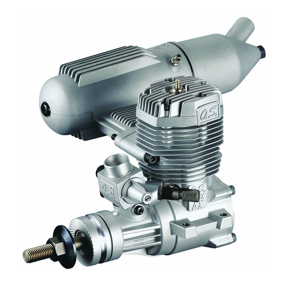
Page 6: Basic Engine Parts
BASIC ENGINE PARTS Glowplug Cylinder head Carburetor Type 61D Cover Plate Propeller washer Beam Mount Propeller nut Crankshaft Crankcase Drive Hub Warning: BEFORE STARTING Make sure that the propeller is well Tools, accessories, etc. The following items balanced. An unbalanced propeller and/or are necessary for operating the engine. - Page 7 FUEL Reminder! Model engine fuel is poisonous. Do not The 65AX should be operated on a methanol based fuel allow it to come into contact with the eyes or containing not less than 18% (volumetric) castor oil, or a mouth. Always store it in a clearly marked top quality synthetic lubricant (or a mixture of both), plus container and out of the reach of children.
-
Page 8: Installation
LONG SOCKET WRENCH WITH PLUG GRIP TOOLS Recommended easy removal HEX Screwdriver replacement of the angled and recessed Necessary for engine installation. glowplug, the O.S.Long Socket Wrench 1.5mm, 2.5mm incorporates a special grip. Phillips Screwdriver No.2, etc. End Wrenches 10mm, etc. SCREWDRIVER Necessary for carburetor adjustments. -
Page 9: Installation Of The Standard Accessories
Make sure that these mounting beams are accurately ● How to fasten the mounting screws. aligned and firmly integrated with the airframe, Hardwood mounting beams reinforcing the adjacent structure to absorb vibration. Tighten second nut Use 4mm or larger steel screws, preferably Allen 3mm steel nuts firmlydown onto first nut. - Page 10 INSTALLING SILENCER E-4010A Silencer Secure the silencer to the engine by means of Assembly screw two retaining screws supplied after the engine is securely mounted to a test bench or a model. Cone baffle The exhaust outlet of the silencer can be rotated Turn to requlred position to any desired position in the following manner: Loosen the locknut and assembly screw.
-
Page 11: Fuel Tank Location
FUEL TANK LOCATION Suggested fuel tank capacity is approx The Fuel line pickup weight should be 10mm 350cc. This will allow 10-12 minute flights. away from the back of the tank. Position the fuel tank so that approximately Make sure that the tank is well rinsed out 1/3 of the tank height is above the center line with methanol or glow fuel before installation of the needlevalve. -
Page 12: Mixture Controls
MIXTURE CONTROLS Two mixture controls are provided on this Carburetor. Needle Valve The Needle Valve When set to produce maximum power at full throttle, this establishes the basic fuel/air Mixture Control Valve mixture strength. The correct mixture is then maintained by the carburetor's built-in Mixture Control Valve of the carburetor is set at automatic mixture control system to cover basic position ( a little on the rich side) at the... -
Page 13: Starting
STARTING Be sure to use an electric starter to Element glows when energized. start the engine. Pliers Never fail to check the tightness of screws and nuts, especially engine mounting and moving parts (e.g. throttle lever). Replace the plug when the element does not glow or is burnt out. - Page 14 Attention : How to stop the engine Do not choke the carburetor air intake when Pull down the throttle lever and trim lever on applying the starter. This could cause an the transmitter fully. excessive amount of fuel to be drawn into the Note: cylinder which may initiate a hydraulic lock and Make sure that the throttle linkage is made...
- Page 15 Optimum needle setting(1) During subsequent flights, the needle-valve can be gradually closed to give more power. Slowly advance the throttle to its fully open However, if the engine shows signs of position, then gradually close the needle-valve running too lean, the next flight should be until the exhaust note begins to change.
-
Page 16: Mixture Control Valve Adjustment
MIXTURE CONTROL VALVE ADJUSTMENT With the engine running, close the throttle and In this case, turn the Mixture Control Screw allow it to idle for about five seconds, then counter-clockwise 90 degrees to positively open the throttle fully. If, at this point, the enrich the idle mixture, then turn the screw engine is slow to pick up and produces an clockwise gradually until the engine regains full... -
Page 17: Realignment Of Mixture Control Valve
REALIGNMENT OF MIXTURE CONTROL VALVE SUBSEQUENT STARTING PROCEDURE In the course of making carburetor adjustments, it is Once the optimum needle-valve setting has just possible that the Mixture Control Valve may be been established (see page 29, Needle-valve inadvertently screwed in or out too far and thereby adjustment diagram) the procedure for starting moved beyond its effective adjustment range. -
Page 18: Trouble Shooting When The Engine Fails To Start
TROUBLE SHOOTING WHEN THE ENGINE FAILS TO START Four key points For quick, reliable starting, the following four conditions are required. 1 Good compression. 2 Adequate "glow" at glowplug. 3 Correct mixture. 4 Sufficient electric starter rotating speed. If the engine fails to start, or does not keep running after being started, check symptoms against the following chart and take necessary corrective action. -
Page 19: Care And Maintenance
CARE AND MAINTENANCE Please pay attention to the matters Install an in-line fuel filter between the tank described below to ensure that your engine and carburetor to prevent dirt and dust in the serves you well in regard to performance, tank from entering the carburetor. -
Page 21: Carburetor Exploded View
CARBURETOR EXPLODED VIEW N.+M3x6 N.+M3.5x6 S.M3X3 Type of screw N...Round Head Screw S...Set Screw CARBURETOR PARTS LIST Description Code No. 22081408 Throttle Lever Assembly 22081313 Throttle Lever Retaining Screw 26981200 Carburetor Rotor 25781600 Mixture Control Valve Assembly 46066319 "O" Ring (L) (2pcs.) 22781800 "O"... -
Page 22: O.s. Genuine Parts & Accessories
O.S. GENUINE PARTS & ACCESSORIES O.S.GLOW PLUG RADIAL MOTOR MOUNT SILENCER EXTENSION ADAPTORS (71905200) No.8 Width Screw hole pitch (71608001) 14.5mm 42.0mm (26625340) No.10 (Former A5) Long (26625500) 35.0mm 42.0mm (71605100) SILENCER E-4050 SPINNER NUT LONG PROPELLER NUT SETS (27426000) 5/16"-24 5/16"-24 (45024000) -
Page 23: Three View Drawing
114.6 THREE VIEW DRAWING SPECIFICATIONS Displacement 10.63 cc / 0.649 cu.in. Bore 24.0 mm / 0.945 in. Stroke 23.5 mm / 0.925 in. 37.7 Practical R.P.M. 2,500-12,000 r.p.m. Power output 1.75 hp / 16.000 r.p.m. Weight 497 g / 17.53 oz. E-4010A Silencer Assembly 156 g / 5.50 oz.