Table of Contents
Advertisement
Quick Links
It is of vital importance, before attempting to operate
your engine, to read the general 'SAFETY
INSTRUCTIONS AND WARNINGS' section on
pages 2-5 of this booklet and to strictly adhere to the
advice contained therein.
Also, please study the entire contents of this
instruction manual, so as to familiarize yourself
with the controls and other features of the engine.
Keep these instructions in a safe place so that you
may readily refer to them whenever necessary.
It is suggested that any instructions supplied with
the model, radio control equipment, etc., are
accessible for checking at the same time.
INSTALLATION OF THROTTLE SERVO
INTRODUCTION, ENGINE PARTS NAME
CONTENTS
2-5
STARTING, RUNNING-IN ("Breakingin")
6-7
ADJUSTMENT CHART
8-9
10-11
ENGINE EXPLODED VIEW & PARTS LIST
12-15
CARBURETOR EXPLODED VIEW & PARTS LIST
16
17
18-19
1
20-23
24-28
29
30-31
32-35
36-37
38-39
40
41
42
Advertisement
Table of Contents

Related Manuals for O.S. engine MaX-37SZ-HRING


Summary of Contents for O.S. engine MaX-37SZ-HRING
-
Page 1: Table Of Contents
It is suggested that any instructions supplied with the model, radio control equipment, etc., are accessible for checking at the same time. CONTENTS SAFETY INSTRUCTIONS AND WARNINGS ABOUT YOUR O.S. ENGINE STARTING, RUNNING-IN ("Breakingin") 20-23 ADJUSTMENT 24-28 NOTES ON INSTALLING... -
Page 2: Safety Instructions And Warnings About Your O.s. Engine
As owner, you, alone, are responsible for the safe operation of your engine, so act with discretion and care at all times. If at some future date, your O.S. engine is acquired by another person, we would respectfully request that these instructions are also passed on to its new owner. - Page 3 ! NOTES • • This engine was designed for model After starting the engine, carry out any needle- helicopters. Do not attempt to use it for any valve readjustments after stopping the rotor by other purpose. closing the throttle to the lowest r.p.m.. Stop the engine before attempting to make •...
-
Page 4: Notes On Installing Cooling-Fan And Clutch
Notes on installing cooling fan and clutch Do not use a tool which locks piston when installing a cooling-fan and clutch, or top of the piston may be damaged. Also, do not insert a screw driver or the similar into the exhaust port. -
Page 5: Notes When Applying An Electric Starter
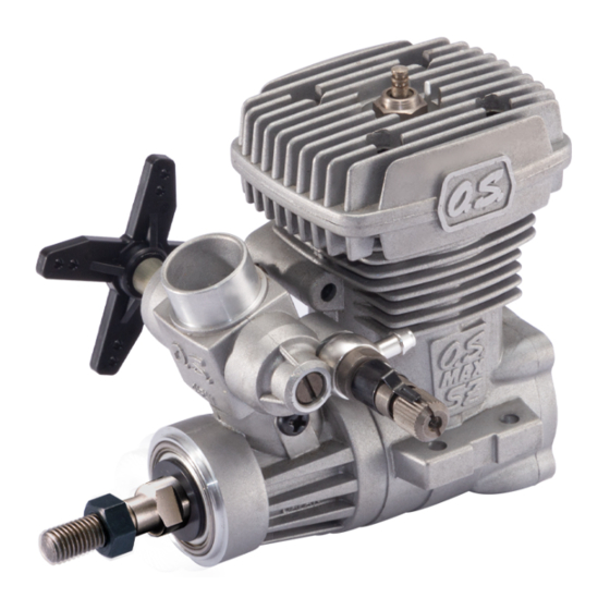
NOTES WHEN APPLYING AN ELECTRIC STARTER Because of this initial tightness, a standard electric starter may have difficulty in rotating the engine when cold, before it has been adequately run-in. In this case, use a high-torque type starter. Do not over-prime. This could cause a hydraulic lock and damage the engine on application of the electric starter. - Page 6 INTRODUCTION This is a high performance engine STANDARD ACCESSOIES designed small-sized radio- controlled helicopters. Glow Plug No.8 Since the mounting bolt pattern of the engine as well as silencer is the same as Throttle Lever Assembly those of the 32SX-H, it can be directly replaced with the 32SX-H and most of other 32-39 size engines.
-
Page 7: Before Starting
BEFORE STARTING Tools, accessories, etc.The following items are In case of 1.5volt dry cell necessary for operating the engine. Battery leads Items necessary for starting Battery leads These are used to conduct current from the battery to the glowplug. Basically, two leads, with clips, are Make sure glowplug element required, but, for greater conve- glows bright red inside room... -
Page 8: Installation Of The Engine
Socket Drivers Needle Nose Pliers 5mm, 5.5mm, 7mm INSTALLATION OF THE ENGINE The under-surfaces of all O.S. engine beam CORRECT mounting lugs are precision machined flat and exactyly parallel to the engine's horizontal axis. It is essential that the engine mounts in the model are also accurately made and aligned. -
Page 9: Installation Of The Standard Accessories
INSTALLATION OF THE STANDARD ACCESSORIES INSTALLING THE GLOWPLUG INSTALLATION OF THE THROTTLE LEVER Install washer on glowplug and insert carefully into Throttle lever is not installed on the carburetor Heatsink-head, making sure that it is not cross- when the engine leaves the factory. threaded before tightening firmly. -
Page 10: Carburetor Controls
CARBURETOR CONTROLS With a fixed-wing model, power failure is rarely a serious threat to the safety of the aircraft since it can usually glide down to a safe landing. In a helicopter, on the other hand, it is vitally imporant that the engine keeps running and that there is a quick and reliable response to the throttle in order to ensure safe ascent MIxture Control Valve... - Page 11 STARTING Be sure to use an electric starter to start Element glows when energized. the engine. Pliers Never fail to check the tightness of screws ! and nuts, especially engine mounting and moving parts (e.g. throttle lever). Be sure to use a muffler pressurized fuel feed. Replace the plug when the Use the same fuel as you intend to employ for element does not glow or is...
- Page 12 Preparation of starting Note: Make sure that the transmitter Make sure that the throttle linkage is made so that throttle stick is at the fully closed the throttle is fully closed when the throttle lever position and the throttle trim at as well as trim lever on the transmitter are fully center position, and make sure that pulled down.
-
Page 13: Adjustment
ADJUSTMENT The following adjustments are approximately correct This enables the full r.p.m. range, from idling to full when using a fuel containing 18-25% lubricant and power, to be controlled by the throttle stick, and 10-30% nitromethane. then allows the engine to be stopped, from the transmitter, by closing the throttle completely with Bear in mind that fuels containing relatively large the trim lever. - Page 14 When satisfactory hovering flight has been Now re-check hovering performance and, if achieved, land the modeI again and re-check the necessary, fine-tune the mixture for hovering flight. engine's idle qualities. N For helicopters, good throttle response at medium After about 10 seconds of idling, open the throttle r.p.m.
- Page 15 CARBURETOR CLEANLINESS SUBSEQUENT READJUSTMENTS The correct functioning of the carburetor depends on Once the engine has been run-in and the carburetor its small fuel orifices remaining clear. The minute controls properly set up, it should be unnecessary to alter the mixture settings, except to make minor particles of foreign matter that are present in any fuel adjustments to the Needle Valve occasionally, to take can easily partially obstruct these orifices and upset...
-
Page 16: Care And Maintenance
CARE AND MAINTENANCE Please pay attention to the matters Install an in-line fuel filter between the tank described below to ensure that your engine and carburetor to prevent foreign matter in serves you well in regard to performance, the tank from entering the carburetor. reliability and long life. -
Page 17: Trouble Shooting
TROUBLE SHOOTING Symptom Engine fails to fire. Corrective action Cause Fuel tank is empty. Fill the tank with fuel and repeat. Fuel not reaching the engine. Priming procedure. Glowplug element is burnt out. Replace glowplug. Glowplug battery discharged Recharge or replace the battery. Clogged fuel filter. - Page 18 Symptom Unstable idle Corrective action Cause Use suggested glowplug in the instructions. Unsuitable glowplug Unsuitable fuel Do not use extremely high nitro or low oil fuel. Silencer is disconnected or is loose Install silencer securely. Symptom Not reaching expected peak r.p.m. Corrective action Cause Set the needle only after warming up.
- Page 20 CARBURETOR EXPLODED VIEW C.M3x8 N.+M3.5x5 * Type of screw C…Cap Screw M…Oval Fillister-Head Screw F…Flat Head Screw N…Round Head Screw S…Set Screw CARBURETOR PARTS LIST Description Code No. 29085140 Throttle Lever Assembly 22826131 Throttle Lever Retaining Screw (2pcs.) 23483200 Carburetor Rotor 23483100 Carburetor Body 45581820...
-
Page 21: O.s. Genuine Parts & Accessories
O.S. GENUINE PARTS & ACCESSORIES GLOWPLUG SUPER FILTER CRANKSHAFT CLAMP DRIVE HUB (71530600) ( L ) (72403050) (23408000) No.7 (71607100) No.8 (71608001) No.10 (Former A5) (71605100) LONG SOCKET WRENCH LOCK WASHER CAP SCREW SET WITH PLUG GRIP (10set) M2.6x7 (10pcs.) (71521000) (79871020) (55500002) -
Page 22: Memo
MEMO 6-15 3-Chome Imagawa Higashisumiyoshi-ku Osaka 546-0003, Japan TEL. (06) 6702-0225 URL : http://www.os-engines.co.jp FAX. (06) 6704-2722 60091520 061106 Copyright 2004 by O.S.Engines Mfg. Co., Ltd. All rights reserved. Printed in Japan.