Carrier 40FKA Installation Instructions Manual
Hide thumbs
Also See for 40FKA:
- Installation instructions manual (17 pages) ,
- Installation and setup instructions (16 pages)
Table of Contents
Advertisement
Visit www.carrier.com
NOTE: Read entire manual before starting installation.
This symbol → indicates a change from the last publication.
See Back Page for QUICK REFERENCE COMFORT HEAT
SET-UP INSTRUCTIONS.
SAFETY CONSIDERATIONS
Improper installation, adjustment, alteration, service, maintenance,
or use can cause explosion, fire, electrical shock or other condi-
tions which may cause personal injury or property damage.
Consult a qualified installer, service agency, or your distributor or
branch for information or assistance. The qualified installer or
agency must use factory-authorized kits or accessories when
modifying this product. Refer to the individual instructions pack-
aged with the kits or accessories when installing.
Follow all safety codes. Wear safety glasses and work gloves. Use
quenching cloth for brazing operations. Have fire extinguisher
available. Read these instructions thoroughly and follow all
Manufacturer reserves the right to discontinue, or change at any time, specifications or designs without notice and without incurring obligations.
Book 1 4
PC 101
Catalog No. 534-011
Tab 3d 2e
Installation Instructions
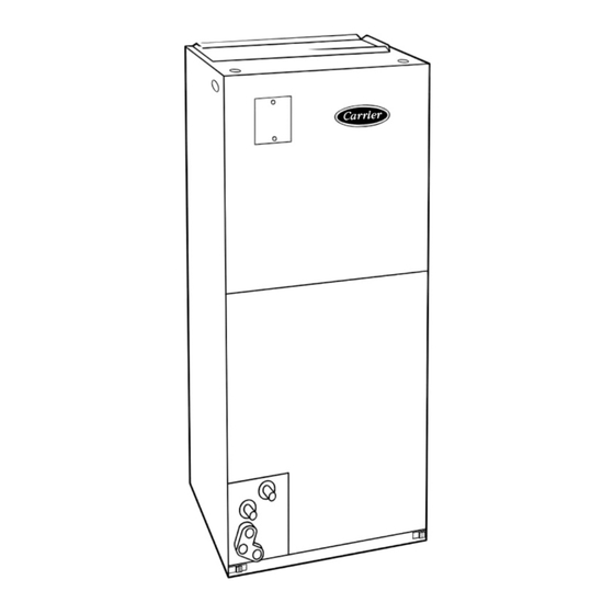
40FKA FAN COIL
Fig. 1—Comfort Heat Pump System
Printed in U.S.A.
Comfort Heat Pump System
warnings or cautions attached to the unit and in installation
instructions or manuals. Consult local building codes and National
Electrical Code (NEC) for special requirements.
Recognize safety information. This is the safety-alert symbol
When you see this symbol on the unit and in instructions or
manuals, be alert to the potential for personal injury.
Understand the signal words DANGER, WARNING, and CAU-
TION. These words are used with the safety-alert symbol. DAN-
GER identifies the most serious hazards which will result in severe
personal injury or death. WARNING signifies hazards which
could result in personal injury or death. CAUTION is used to
identify unsafe practices which would result in minor personal
injury or product and property damage. NOTE is used to highlight
suggestions which will result in enhanced installation, reliability,
or operation.
THERMIDISTAT ™
CONTROL
OUTDOOR TEMPERATURE SENSOR
Form 40FK-5SI
40FKA
002-006
Pg 1
7-00
Replaces: 40FK-3SI
.
A98049
Advertisement
Table of Contents

Related Manuals for Carrier 40FKA


Summary of Contents for Carrier 40FKA
-
Page 1: Installation Instructions
Read these instructions thoroughly and follow all THERMIDISTAT ™ CONTROL OUTDOOR TEMPERATURE SENSOR 40FKA FAN COIL A98049 Fig. 1—Comfort Heat Pump System Manufacturer reserves the right to discontinue, or change at any time, specifications or designs without notice and without incurring obligations. -
Page 2: Installation
3 screws. (See Fig. 6—factory-shipped inset.) MODULAR UNITS c. Remove filler plate (A) and install air splitter (B) in place The 40FKA Fan Coil in size 006 is a 2-piece modular unit. of filler plate. Modular construction allows installer to disassemble unit into 2 components, coil box and blower box, for ease of installation. -
Page 3: Downflow Installations
To convert units for downflow applications, refer to Installation Instructions supplied with kit for proper installation. For 40FKA unit size 003, use kit Part No. KFADC0201SLP. For 40FKA unit REAR CORNER sizes 002, 005, and 006 use kit Part No. KFADC0401ACL. Use BRACKET fireproof resilient gasket, 1/8- to 1/4-in. - Page 4 A-COIL HORIZONTAL LEFT PRIMARY SECONDARY DRAIN FIELD DRAIN SUPPLIED HANGING STRAPS 002-005 21-IN. 006 24-IN. FRONT SERVICE CLEARANCE (FULL FACE UNIT OF UNIT) LOW VOLT ENTRY OPTIONS 1 3 /4 IN. FILTER ACCESS CLEARANCE PRIMARY DRAIN SECONDARY DRAIN POWER ENTRY OPTIONS A00096 →...
- Page 5 REFRIGERANT AIR SEAL CONNECTIONS ASSEMBLY HORIZONTAL RIGHT APPLICATION COIL SUPPORT RAIL COIL BRACKET DRAIN PAN SUPPORT BRACKET COIL SUPPORT RAIL COIL BRACKET HORIZONTAL DRAIN PAN PRIMARY DRAIN HORIZONTAL RIGHT SECONDARY DRAIN HORIZONTAL RIGHT A00071 → Fig. 6—A-Coil in Horizontal Right-Application COIL FACTORY SHIPPED BRACKET...
-
Page 6: Ductwork Acoustical Treatment
SENSOR CONNECTION A98232 A98233 Fig. 8—40FKA Fan Coil with 1-Speed Air Conditioner Fig. 9—40FKA Fan Coil with 2-Speed Air Conditioner discharge plenum and ductwork for a distance of 36 in. from unit. For units without electric heat: Use accessory downflow base to maintain proper clearance on 1. - Page 7 Super Comfort Heat and Super Dehumidify options are possible NOTE: Where local codes require thermostat wiring be routed when the 40FKA Fan Coil is installed with an outdoor temperature through conduit or raceways, splices can be made inside the fan sensor (Super Comfort Heat only) and the factory supplied coil unit.
-
Page 8: Ground Connections
GROUND CONNECTIONS UNIT The cabinet must have an uninterrupted or unbroken ground according to NEC, ANSI/NFPA 70 and local codes to ″ ⁄ minimize personal injury if an electrical fault should occur. The ground may consist of electrical wire or metal conduit when installed in accordance with existing electrical codes. - Page 9 (See Figs. 16 and 18.) The factory setting is AC. (See Fig. 19, C as indicated.) The 40FKA Fan Coil must be configured to operate properly with system components with which it is installed. To successfully AC/HP CFM ADJUST – SELECT MEDIUM, LOW, OR HIGH...
-
Page 10: Low-Voltage Circuit Fusing And Reference
SEC1 SEC2 EASY SELECT AUX HEAT KW/CFM 0-30 0-20 0-10 1075 AC/HP SIZE SYSTEM TYPE HP-COMFORT HP-EFF AC/HP CFM ADJUST ON/OFF DELAY CONTINUOUS FAN AUX1 HUM1 AUX2 HUM2 CEBD430226-01B CESS430226-01B 24VAC HEATER/MOTOR 12-PIN MATE-N-LOCK ELECTRIC HEAT CONNECTOR A95276 Fig. 16—PCB Wiring Arrangement ON/OFF DELAY –... - Page 11 3. Dry coil at 230 volts and with 10kw heater and filter installed. 4. Airflows shown are at standard air conditions. → Table 3—40FKA Fan Coil Airflow Delivery (CFM) in Heat Pump Only Heating Mode OPERATING MODE—HEAT PUMP ONLY HEATING...
- Page 12 1810 2085 1750 1810 2085 * Airflow not recommended for heater/system size. NOTE: LO, NOM, and HI refer to AC/HP CFM ADJUST selection. Table 5—40FKA Minimum CFM for Electric Heater Application HEAT PUMP COIL UNIT HEATER SIZE KW UNIT SIZE...
- Page 13 Step 10—40FKA Fan Coil Sequence Of Operation jumper J2 when using 5-, 8-, or 10-kw heaters. The 40FKA will supply airflow in a range which is more than 8. Remove jumper J1 to activate dehumidify modes. twice the range of a standard fan coil. It is designed to provide nominal cooling capacities at a 50°F evaporator temperature and...
- Page 14 → Step 11—Troubleshooting ICM Motor and Controls 1. If the indoor temperature is below the temperature set point and the humidity is greater than the humidity set point, the Thermidistat closes circuit R to O, opens circuits R to DH and R to G, and cycles circuit R to Y/Y2 (for single speed system High voltage is always present at motor.
- Page 15 J1 JUMPER – PULL FOR DEHUMIDIFICATION CONTROL LOW VOLTAGE SCREW TERMINALS J2 JUMPER – PULL FOR HEAT STAGING SEC1 SEC2 DEHUMIDIFICATION INPUT EASY SELECT 24 VAC HOT AUX HEAT KW/CFM 0-30 0-20 0-10 1075 AUXILARY HEAT STAGE 1 AUXILIARY HEAT STAGE 2 AC/HP SIZE LOW SPEED COMPRESSOR SYSTEM TYPE...
- Page 16 → Table 7—Wiring Connections of FK Fan Coil Wiring Harness 16-PIN PLUG ON WIRING HARNESS TO MOTOR WIRING HARNESS CONNECTION TO EASY SELECT BOARD Signal on Pin with Pin # on 12-Pin Plug Pin # on 16-Pin Plug Description Wire Color Screw Terminal Jum- or Set-up Selection pered to R*...
- Page 17 • Option 12 (Heaters during Defrost) - setting "2" is suggested for all heaters • Option 16 (Super Comfort Heat) - set to ON for R-22 MOLEX 12-PIN CONNECTOR systems. For Puron applications, set to OFF. A98290 Fig. 18—40FKA Printed CIrcuit Board with Comfort Heat Pump Set-up Guide...
- Page 20 Copyright 2000 CARRIER Corp. • 7310 W. Morris St. • Indianapolis, IN 46231 40fk5si Manufacturer reserves the right to discontinue, or change at any time, specifications or designs without notice and without incurring obligations. Book 1 4 PC 101 Catalog No. 534-011 Printed in U.S.A.