Table of Contents
Advertisement
Quick Links
harman/kardon
harman/kardon
AVR 260/230
7 x 50W 7.1 CHANNEL A/V RECEIVER
ESD WARNING
FRONT AND REAR PANELS
REMOTE CONTROL
TROUBLESHOOTING GUIDE
PROCESSOR RESET
BASIC SPECIFICATIONS
PACKAGE LISTS AND PARTS
DISASSEMBLY
Released EU2010
CONTENTS
2
EXPLODED VIEW AND PARTS
3
ELECTRICAL PARTS LIST
8
SEMICONDUCTOR PINOUTS
10
PCB DRAWINGS
10
BLOCK DIAGRAM
11
WIRING DIAGRAM
12
AMP BIAS ADJUSTMENT
13
SCHEMATIC DIAGRAMS
Harman Consumer Group, Inc.
8500 Balboa Boulevard
Northridge, California 91329
AVR 260/230 Service Manual
Service Manual
Rev 0, 07/2010
14
15
49
109
116
117
118
119-131
Page 1 of 131
Advertisement
Table of Contents

Related Manuals for Harman Kardon AVR 260


Summary of Contents for Harman Kardon AVR 260
-
Page 1: Service Manual
AVR 260/230 Service Manual harman/kardon Service Manual AVR 260/230 7 x 50W 7.1 CHANNEL A/V RECEIVER CONTENTS ESD WARNING EXPLODED VIEW AND PARTS FRONT AND REAR PANELS ELECTRICAL PARTS LIST REMOTE CONTROL SEMICONDUCTOR PINOUTS TROUBLESHOOTING GUIDE PCB DRAWINGS PROCESSOR RESET... - Page 2 AVR 260/230 Service Manual Some semiconductor (solid state) devices can be damaged easily by static electricity. Such components commonly are called Electrostatically Sensitive (ES) Devices. Examples of typical ES devices are integrated circuits and some field effect transistors and semiconductor "chip"...
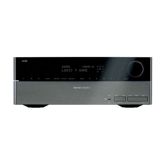
- Page 3 AVR 260/230 Service Manual FRONT-PANEL CONTROLS � Resolution Audio Effects Surround Modes Back/Exit Source List Info Video Modes Composite Analog 0 Volume Control: Turn this knob clockwise to increase the volume, 7 Info Settings Button: Press this button to directly access the AVR’s...
- Page 4 AVR 260/230 Service Manual FRONT-PANEL CONTROLS D Speaker/Channel Input Indicators: These indicators are multipurpose, indicating either the speaker type selected for each channel or the incoming data-signal configuration. The left, center, right, right surround and left surround speaker indicators are composed of three boxes, while the subwoofer is a single box.
- Page 5 AVR 260/230 Service Manual FRONT-PANEL CONTROLS � Resolution Audio Effects Surround Modes Back/Exit Source List Info Video Modes Composite Analog 0 Volume Control: Turn this knob clockwise to increase the volume, 7 Info Settings Button: Press this button to directly access the AVR’s...
- Page 6 H RS-232 Serial Port: This specialized connector may be used with back left channel positive (+) and negative (–) connections and the your personal computer in case Harman Kardon offers a software tan and black terminals are the surround back right positive (+) and upgrade for the receiver at some time in the future.
- Page 7 HDMI-equipped video display. product such as a VCR, DVD player, satellite receiver, cable set-top box, personal video recorder or video game to the AVR 260, you may use either a composite or S-video connection, but not both. Page 7 of 131...
-
Page 8: Remote Control Functions
AVR 260/230 Service Manual REMOTE CONTROL FUNCTIONS AVR Power On AVR Power Off Source Selectors Audio Effects Button Transport Controls Menu Navigation LKM N Sleep Button Main Tuning Buttons Last Button Numeric Keys Video Mode Button Menu Button Activity Button... - Page 9 REMOTE CONTROL FUNCTIONS Video Modes Button: The remote is capable of operating the AVR 260 and most Harman Kardon CD Press this button to go directly to the Video changers or players, CD Recorders and Blu-ray players, using the control codes Modes Menu.
-
Page 10: Processor Reset
After the pause, reconnect the AC power cord and microprocessor. check the unit’s operation. If the system still malfunctions, a system reset may If these steps do not solve the problem, consult an authorized Harman Kardon clear the problem. service depot. -
Page 11: Audio Section
Stereo Separation 40dB @ 1kHz Harman Kardon and Logic 7 are trademarks of Harman International Industries, Incorporated, registered in the United States and/or other countries. EzSet/EQ, Designed to Entertain and The Bridge II logo are trademarks of Harman International Industries, Incorporated. - Page 12 AVR 260/230 Service Manual Page 12 of 131...
- Page 13 AVR 260/230 Service Manual Page 13 of 131...
- Page 14 AVR 260/230 Service Manual Page 14 of 131...
- Page 15 AVR 260/230 Service Manual AVR260/230 Electrical & Mechanical Parts List Level Drawing No (Value) Ref. # Part Number Description CGB1A218Z BADGE , AVR260 CGL1A222 INDICATOR , VOLUME AVR130/230/330 CGR3A436 COVER , JACK A CGR3A437 COVER , JACK B CGU1A318Y...
-
Page 16: Screw
AVR 260/230 Service Manual BOTTOM CHASSIS ASS'Y Level Description Drawing No (Value) Ref. # Part Number CKF7A337W PANEL , REAR CKL1A094 FOOT , A AVR350 CKL1A095 FOOT , B AVR350 CLZ9W003Z FERRITE , RING 29X7.7X19 CMD1A636 BRACKET , PCB... - Page 17 AVR 260/230 Service Manual FRONT PCB ASSY Level Description Drawing No (Value) Ref. # Part Number ..5 C869 CCEA1EH470T CAP , ELECT 47UF 25V ..5 C870 CCBS1H681KBT CAP , CERAMIC(680PF/50V) CH UP025 B681K-A-B Z ..5 C871 CCBS1H681KBT CAP , CERAMIC(680PF/50V) CH UP025 B681K-A-B Z ..5...
- Page 18 AVR 260/230 Service Manual FRONT PCB ASSY Level Description Drawing No (Value) Ref. # Part Number ..5 R805 CRD20TJ104T RES , CARBON 100K OHM 1/5W J ..5 R806 CRD20TJ472T RES , CARBON 4.7K OHM 1/5W J ..5 R824 CRD20TF2200T RES , CARBON(220 OHM, 1%) ..5...
-
Page 19: Screw , Special
AVR 260/230 Service Manual FRONT PCB ASSY Level Description Drawing No (Value) Ref. # Part Number ..5 CLZ9Z028Z FERRITE , CORE(21.2X6.4X12.7) K5C T ..5 CWZAVR155BN41ZA 7P WIRE ASS'Y 1Core 3turn (2mm,500mm) ...4 BN81 CWB1C907200BM WIRE ASS'Y ...4 BN84 CWB2B905080EN WIRE ASS'Y ...4... - Page 20 AVR 260/230 Service Manual MAIN PCB ASSY Level Description Drawing No (Value) Ref. # Part Number ..5 C683 CCEA1HH100T CAP , ELECT 10UF 50V ..5 C684 CCEA1HH100T CAP , ELECT 10UF 50V ..5 C685 CCEA1HH100T CAP , ELECT 10UF 50V ..5...
- Page 21 AVR 260/230 Service Manual MAIN PCB ASSY Level Description Drawing No (Value) Ref. # Part Number ..5 D801 CVD1SS133MT DIODE 1SS133 ..5 D802 CVD1SS133MT DIODE 1SS133 ..5 D803 CVD1SS133MT DIODE 1SS133 ..5 D804 CVD1SS133MT DIODE 1SS133 ..5 D901 CVD1N4003SRT...
- Page 22 AVR 260/230 Service Manual MAIN PCB ASSY Level Description Drawing No (Value) Ref. # Part Number ..5 Q813 HVTKTC3200GRT KTC3200GR ..5 Q814 HVTKTA1268GRT KTA1268GR ..5 Q815 HVTKTC3200GRT KTC3200GR ..5 Q816 HVTKTA1268GRT KTA1268GR ..5 Q817 HVTKTA1268GRT KTA1268GR ..5 Q818 HVTKTC3200GRT KTC3200GR ..5...
- Page 23 AVR 260/230 Service Manual MAIN PCB ASSY Level Description Drawing No (Value) Ref. # Part Number ..5 R558 CRD20TJ273T RES , CARBON 27K OHM 1/5W J ..5 R559 CRD20TJ273T RES , CARBON 27K OHM 1/5W J ..5 R560 CRD20TJ273T...
- Page 24 AVR 260/230 Service Manual MAIN PCB ASSY Level Description Drawing No (Value) Ref. # Part Number ..5 R668 CRD25TJ470T RES , CARBON (47 OHM) ..5 R669 CRD25TJ470T RES , CARBON (47 OHM) ..5 R670 CRD25TJ470T RES , CARBON (47 OHM) ..5...
- Page 25 AVR 260/230 Service Manual MAIN PCB ASSY Level Description Drawing No (Value) Ref. # Part Number ..5 R845 CRD20TJ561T RES , CARBON 560 OHM 1/5W J ..5 R848 CRD20TJ273T RES , CARBON 27K OHM 1/5W J ..5 R849 CRD20TJ273T...
-
Page 26: Screw , Special
AVR 260/230 Service Manual MAIN PCB ASSY Level Description Drawing No (Value) Ref. # Part Number ..5 R986 CRD20TJ102T RES , CARBON 1K OHM 1/5W J ..5 R987 CRD20TJ561T RES , CARBON 560 OHM 1/5W J ..5 R988 CRD20TJ562T RES , CARBON 5.6K OHM 1/5W J... - Page 27 AVR 260/230 Service Manual MAIN PCB ASSY Level Description Drawing No (Value) Ref. # Part Number ...4 C637 CCEA1JH101E CAP , ELECT 100UF 63V ...4 C638 CCEA1JH101E CAP , ELECT 100UF 63V ...4 C639 CCEA1JH101E CAP , ELECT 100UF 63V ...4...
- Page 28 AVR 260/230 Service Manual POWER PCB ASSY Level Description Drawing No (Value) Ref. # Part Number ..5 C119 CCEA1JH470TS CAP , ELECT 63V/47UF/105'C ..5 C120 CCEA1JH470TS CAP , ELECT 63V/47UF/105'C ..5 C121 CCBS1H103ZFT CAP , CERAMIC 0.01UF 50V Z ..5...
- Page 29 AVR 260/230 Service Manual POWER PCB ASSY Level Description Drawing No (Value) Ref. # Part Number ..5 R875 CRD20TJ331T RES , CARBON 330 OHM 1/5W J ..5 R876 CRD20TJ331T RES , CARBON 330 OHM 1/5W J ..5 R877 CRD20TJ331T...
- Page 30 AVR 260/230 Service Manual POWER PCB ASSY Level Description Drawing No (Value) Ref. # Part Number ...4 CN96 CJP15GA19ZY WAFER ...4 CN98 HJP08GB131ZK WAFER ...4 C122 CCEA1JH101E CAP , ELECT 100UF 63V ...4 C129 CCEA1EH822E CAP , ELECT(KR3, 8200UF/25V, 18X30 KR3-25V822MU ...4...
- Page 31 AVR 260/230 Service Manual INPUT PCB ASSY Level Description Drawing No (Value) Ref. # Part Number ..6 C269 CCUS1A105KC CAP , CHIP 1UF 10V K ..6 C274 CCUS1A105KC CAP , CHIP 1UF 10V K ..6 C277 CCUS1H104KC CAP , CHIP 0.1UF 50V K...
- Page 32 AVR 260/230 Service Manual INPUT PCB ASSY Level Description Drawing No (Value) Ref. # Part Number ..6 C398 CCUS1H151JA CAP , CHIP 150PF 50V J ..6 C532 CCUS1H182KC CAP , CHIP(1800PF/50V/1608/X7R) 1800PF 50V K ..6 C534 CCUS1H182KC CAP , CHIP(1800PF/50V/1608/X7R) 1800PF 50V K ..6...
- Page 33 AVR 260/230 Service Manual INPUT PCB ASSY Level Description Drawing No (Value) Ref. # Part Number ..6 C782 CCUS1H103KC CAP , CHIP 0.01UF 50V K ..6 C783 CCUS1H103KC CAP , CHIP 0.01UF 50V K ..6 C784 CCUS1H103KC CAP , CHIP 0.01UF 50V K...
- Page 34 AVR 260/230 Service Manual INPUT PCB ASSY Level Description Drawing No (Value) Ref. # Part Number ..6 RN79 CRJ104DJ330T RES , 4ARRAY (1608*4) 33 OHM/1608*4 ..6 RN80 CRJ104DJ330T RES , 4ARRAY (1608*4) 33 OHM/1608*4 ..6 RN81 CRJ104DJ330T RES , 4ARRAY (1608*4) 33 OHM/1608*4 ..6...
- Page 35 AVR 260/230 Service Manual INPUT PCB ASSY Level Description Drawing No (Value) Ref. # Part Number ..6 R274 CRJ10DJ222T RES , CHIP (2.2K OHM) 1608 SIZE ..6 R275 CRJ10DJ242T RES , CHIP (2.4K OHM) 1608 SIZE ..6 R276 CRJ10DJ242T RES , CHIP (2.4K OHM)
- Page 36 AVR 260/230 Service Manual INPUT PCB ASSY Level Description Drawing No (Value) Ref. # Part Number ..6 R373 CRJ10DJ512T RES , CHIP (5.1K OHM) 1608 SIZE ..6 R374 CRJ10DJ103T RES , CHIP (10K OHM) 1608 SIZE ..6 R375 CRJ10DJ512T RES , CHIP (5.1K OHM)
- Page 37 AVR 260/230 Service Manual INPUT PCB ASSY Level Description Drawing No (Value) Ref. # Part Number ..6 R758 CRJ10DJ103T RES , CHIP (10K OHM) 1608 SIZE ..6 R759 CRJ10DJ820T RES , CHIP (82 OHM) 1608 SIZE ..6 R760 CRJ10DJ105T...
- Page 38 AVR 260/230 Service Manual INPUT PCB ASSY Level Description Drawing No (Value) Ref. # Part Number ..5 C358 CCEA1CH101T CAP , ELECT 100UF 16V ..5 C359 CCEA1CH101T CAP , ELECT 100UF 16V ..5 C360 CCEA1CH101T CAP , ELECT 100UF 16V ..5...
- Page 39 AVR 260/230 Service Manual INPUT PCB ASSY Level Description Drawing No (Value) Ref. # Part Number ...4 CN49 CJP05GA19ZY WAFER , STRAIGHT ...4 CN72 CJP17GA117ZY WAFER ...4 C732 CCEA0JKR3222E CAP , ELECT ...4 IC36 HVIKIA7808API I.C , REGULATOR +8V KIA7808 (KEC) ...4...
- Page 40 AVR 260/230 Service Manual VIDEO PCB ASSY Level Description Drawing No (Value) Ref. # Part Number ..6 R584 CRJ10DJ474T RES , CHIP (470K OHM) 1608 SIZE ..6 R601 CRJ10DJ0R0T RES , CHIP (O OHM) 1608 SIZE ..6 R603 CRJ10DJ0R0T...
- Page 41 AVR 260/230 Service Manual HDMI TORINO PCB ASSY Level Description Drawing No (Value) Ref. # Part Number ..5 C625 CCUS1H104KC CAP , CHIP 0.1UF 50V K ..5 C626 CCSNA0J220B CAP , CHIP TANTAL(22uF/6.3V, NingXiaXRCA45 XXX M XXX AT ..5...
- Page 42 AVR 260/230 Service Manual HDMI TORINO PCB ASSY Level Description Drawing No (Value) Ref. # Part Number ..5 C765 CCUS1H103KC CAP , CHIP 0.01UF 50V K ..5 C766 CCUI1C104KC CAP , CHIP(1005, 16V/0.1UF) ..5 C767 CCUS1H103KC CAP , CHIP 0.01UF 50V K...
- Page 43 AVR 260/230 Service Manual HDMI TORINO PCB ASSY Level Description Drawing No (Value) Ref. # Part Number ..5 C866 CCUI1C104KC CAP , CHIP(1005, 16V/0.1UF) ..5 C867 CCUI1C104KC CAP , CHIP(1005, 16V/0.1UF) ..5 C868 CCSNA0J220B CAP , CHIP TANTAL(22uF/6.3V, NingXiaXRCA45 XXX M XXX AT ..5...
- Page 44 AVR 260/230 Service Manual HDMI TORINO PCB ASSY Level Description Drawing No (Value) Ref. # Part Number ..5 C948 CCUS1H104KC CAP , CHIP 0.1UF 50V K ..5 C949 CCUS1H104KC CAP , CHIP 0.1UF 50V K ..5 C950 CCUS1H104KC CAP , CHIP 0.1UF 50V K...
- Page 45 AVR 260/230 Service Manual HDMI TORINO PCB ASSY Level Description Drawing No (Value) Ref. # Part Number ..5 L813 CLZ9R005Z FERRITE , CHIP BEAD(60ohm, 1608) HCB1608KF-600T30 ..5 L814 CLZ9R005Z FERRITE , CHIP BEAD(60ohm, 1608) HCB1608KF-600T30 ..5 L815 CLZ9R005Z FERRITE , CHIP BEAD(60ohm, 1608) HCB1608KF-600T30 ..5...
- Page 46 AVR 260/230 Service Manual HDMI TORINO PCB ASSY Level Description Drawing No (Value) Ref. # Part Number ..5 RN71 CRJ062IJ330T RES , CHIP NETWORK(1/16W, 33ohm, MNR02M0APJ330 ..5 RN72 CRJ062IJ330T RES , CHIP NETWORK(1/16W, 33ohm, MNR02M0APJ330 ..5 RN73 CRJ062IJ330T RES , CHIP NETWORK(1/16W, 33ohm, MNR02M0APJ330 ..5...
- Page 47 AVR 260/230 Service Manual HDMI TORINO PCB ASSY Level Description Drawing No (Value) Ref. # Part Number ..5 R874 CRJ10DJ103T RES , CHIP (10K OHM) 1608 SIZE ..5 R875 CRJ10DJ103T RES , CHIP (10K OHM) 1608 SIZE ..5 R876 CRJ10DJ103T...
- Page 48 AVR 260/230 Service Manual HDMI TORINO PCB ASSY Level Description Drawing No (Value) Ref. # Part Number ..5 R964 CRJ10DJ101T RES , CHIP (100 OHM) 1608 SIZE ..5 R965 CRJ10DJ0R0T RES , CHIP (O OHM) 1608 SIZE ..5 R969 CRJ10DF8200T RES , CHIP 1% 820 OHM ..5...
- Page 49 AVR 260/230 Service Manual Page 49 of 131...
- Page 50 AVR 260/230 Service Manual (70 Ω) 2SB1560 Darlington Equivalent circuit Silicon PNP Epitaxial Planar Transistor (Complement to type 2SD2390) Application : Audio, Series Regulator and General Purpose External Dimensions MT-100(TO3P) Absolute maximum ratings (Ta=25°C) Electrical Characteristics (Ta=25°C) 2SB1560 Symbol...
- Page 51 AVR 260/230 Service Manual Equivalent circuit 2SD2390 Darlington (70 Ω) Silicon NPN Triple Diffused Planar Transistor (Complement to type 2SB1560) Application : Audio, Series Regulator and General Purpose External Dimensions MT-100(TO3P) Absolute maximum ratings (Ta=25°C) Electrical Characteristics (Ta=25°C) Symbol...
- Page 52 AVR 260/230 Service Manual Page 52 of 131...
- Page 53 AVR 260/230 Service Manual harman/kardon Page 53 of 131...
- Page 54 AVR 260/230 Service Manual harman/kardon Page 54 of 131...
- Page 55 AVR 260/230 Service Manual Page 55 of 131...
- Page 56 AVR 260/230 Service Manual Page 56 of 131...
- Page 57 AVR 260/230 Service Manual harman/kardon Page 57 of 131...
- Page 58 AVR 260/230 Service Manual harman/kardon Page 58 of 131...
- Page 59 AVR 260/230 Service Manual Page 59 of 131...
- Page 60 AVR 260/230 Service Manual Page 60 of 131...
- Page 61 AVR 260/230 Service Manual Page 61 of 131...
- Page 62 AVR 260/230 Service Manual Page 62 of 131...
- Page 63 AVR 260/230 Service Manual Page 63 of 131...
- Page 64 AVR 260/230 Service Manual Page 64 of 131...
- Page 65 AVR 260/230 Service Manual Page 65 of 131...
- Page 66 AVR 260/230 Service Manual Page 66 of 131...
- Page 67 AVR 260/230 Service Manual Page 67 of 131...
- Page 68 AVR 260/230 Service Manual Page 68 of 131...
- Page 69 DATA SHEET harman/kardon AVR 260/230 Service Manual MOS FIELD EFFECT TRANSISTOR µ PA672T N-CHANNEL MOS FET ARRAY FOR SWITCHING The µ PA672T is a super-mini-mold device provided PACKAGE DIMENSIONS (in millimeters) with two MOS FET elements. It achieves high-density +0.1 mounting and saves mounting costs.
- Page 70 AVR 260/230 Service Manual 74ACT04 HEX INVERTER HIGH SPEED: t = 5.0ns (TYP.) at V = 5V LOW POWER DISSIPATION: = 2µA(MAX.) at T =25°C COMPATIBLE WITH TTL OUTPUTS = 2V (MIN.), V = 0.8V (MAX.) 50Ω TRANSMISSION LINE DRIVING...
- Page 71 AVR 260/230 Service Manual Page 71 of 131...
- Page 72 AVR 260/230 Service Manual 74LCX32 LOW VOLTAGE CMOS QUAD 2-INPUT OR GATE WITH 5V TOLERANT INPUTS 5V TOLERANT INPUTS HIGH SPEED: = 5.2ns (MAX.) at V = 3V POWER DOWN PROTECTION ON INPUTS AND OUTPUTS SYMMETRICAL OUTPUT IMPEDANCE: | = I...
- Page 73 AVR 260/230 Service Manual A3S56D30ETP A3S56D40ETP 256M Double Data Rate Synchronous DRAM Pin Assignment (Top View) 66-pin TSOP DQ15 VDDQ VDDQ VSSQ VSSQ DQ14 DQ13 VSSQ VSSQ VDDQ VDDQ 66pin TSOP(II) DQ12 DQ11 VDDQ VDDQ VSSQ VSSQ DQ10 VSSQ...
- Page 74 AVR 260/230 Service Manual ADV7342/ADV7343 PIN CONFIGURATION AND FUNCTION DESCRIPTIONS 64 63 62 61 60 59 58 57 56 55 54 53 52 51 50 49 SFL/MISO DD_IO PIN 1 TEST0 SET1 TEST1 COMP1 DAC 1 DAC 2 ADV7342/ADV7343...
- Page 75 AVR 260/230 Service Manual CS42528 2. PIN DESCRIPTIONS 64 63 62 61 60 59 58 57 56 55 54 53 52 51 50 49 CX_SDIN1 RXP1/G PO 1 CX_SCLK RXP2/G PO 2 CX_LRCK RXP3/G PO 3 RXP4/G PO 4...
- Page 76 AVR 260/230 Service Manual CS4970x4 Data Sheet 32-bit High Definition Audio Decoder DSP Family 8. Device Pin-Out Diagram 8.1 128-Pin LQFP Pin-Out Diagram SD_A0, EXT_A0 GPIO38, PCP_WR# / DS#, SCP2_CLK GPIO11, PCP_A3, AS#, SCP2_MISO / SDA SD_A1, EXT_A1 GPIO10, PCP_A2 / A10, SCP2_MOSI...
- Page 77 AVR 260/230 Service Manual harman/kardon CS4970x4 Data Sheet 32-bit High Definition Audio Decoder DSP Family 8.2 144-Pin LQFP Pin-Out Diagram GPIO9, PCP_A1 / A9 SD_A0, EXT_A0 GPIO8, PCP_A0 / A8 SD_A1, EXT_A1 SD_A2, EXT_A2 GPIO7, PCP_AD7 / D7 GND4 GPIO6, PCP_AD6 / D6...
- Page 78 AVR 260/230 Service Manual ESMT F25L004A PIN CONFIGURATIONS 8-PIN SOIC HOLD 8-PIN PDIP HOLD Publication Date: Apr. 2007 Elite Semiconductor Memory Technology Inc. Revision: 2/32 Page 78 of 131...
- Page 79 AVR 260/230 Service Manual ESMT F25L004A PIN Description Symbol Pin Name Functions To provide the timing for serial input and Serial Clock output operations To transfer commands, addresses or data Serial Data Input serially into the device. Data is latched on the rising edge of SCK.
- Page 80 AVR 260/230 Service Manual ESMT Preliminary F49L320UA/F49L320BA 4. PIN CONFIGURATIONS 4.1 48-pin TSOP 4.2 Pin Description Symbol Pin Name Functions A0~A20 Address Input To provide memory addresses. To output data when Read and receive data when Write. DQ0~DQ14 Data Input/Output The outputs are in tri-state when OE or CE is high.
- Page 81 AVR 260/230 Service Manual Page 81 of 131...
- Page 82 AVR 260/230 Service Manual Page 82 of 131...
-
Page 83: Technical Data
AVR 260/230 Service Manual SEMICONDUCTOR KIA278R00PI TECHNICAL DATA BIPOLAR LINEAR INTEGRATED CIRCUIT 2A ADJUSTABLE LOW DROP VOLTAGE REGULATOR The KIA278R00PI is a Low Drop Voltage Regulator suitable DIM MILLIMETERS 10.00 0.20 for various electronic equipments. It provides constant voltage 15.00 0.20... - Page 84 AVR 260/230 Service Manual SEMICONDUCTOR KIA278R05PI~KIA278R15PI TECHNICAL DATA BIPOLAR LINEAR INTEGRATED CIRCUIT 4 TERMINAL 2A OUTPUT LOW DROP VOLTAGE REGULATOR DIM MILLIMETERS 10.00 0.20 The KIA278R Series are Low Drop Voltage Regulator 15.00 0.20 2.70 0.20 suitable for various electronic equipments.
- Page 85 AVR 260/230 Service Manual SEMICONDUCTOR KIA378R05PI~KIA378R15PI TECHNICAL DATA BIPOLAR LINEAR INTEGRATED CIRCUIT 4 TERMINAL 3A OUTPUT LOW DROP VOLTAGE REGULATOR DIM MILLIMETERS 10.00 0.20 The KIA378R Series are Low Drop Voltage 15.00 0.20 2.70 0.20 Regulator suitable for various electronic equipments.
- Page 86 AVR 260/230 Service Manual Page 86 of 131...
- Page 87 AVR 260/230 Service Manual Page 87 of 131...
- Page 88 AVR 260/230 Service Manual Page 88 of 131...
- Page 89 AVR 260/230 Service Manual Page 89 of 131...
- Page 90 AVR 260/230 Service Manual Page 90 of 131...
-
Page 91: Block Diagram
AVR 260/230 Service Manual LC72723, LC72723M Pin Assignment (DIP16/MFP16) Block Diagram No. 6037-2/8 Page 91 of 131... -
Page 92: General Description
AVR 260/230 Service Manual ESMT M12L16161A SDRAM 512K x 16Bit x 2Banks Synchronous DRAM FEATURES GENERAL DESCRIPTION The M12L16161A is 16,777,216 bits synchronous high JEDEC standard 3.3V power supply data rate Dynamic RAM organized as 2 x 524,288 words by LVTTL compatible with multiplexed address 16 bits, fabricated with high performance CMOS technology. - Page 93 AVR 260/230 Service Manual M24C64 M24C32 64Kbit and 32Kbit Serial I²C Bus EEPROM FEATURES SUMMARY Two-Wire I C Serial Interface Figure 1. Packages Supports 400kHz Protocol Single Supply Voltage: – 4.5 to 5.5V for M24Cxx – 2.5 to 5.5V for M24Cxx-W –...
- Page 94 AVR 260/230 Service Manual M24C64, M24C32 SUMMARY DESCRIPTION These I C-compatible electrically erasable pro- Table 2. Signal Names grammable memory (EEPROM) devices are orga- E0, E1, E2 Chip Enable nized as 8192 x 8 bits (M24C64) and 4096 x 8 bits (M24C32).
- Page 95 AVR 260/230 Service Manual Page 95 of 131...
- Page 96 AVR 260/230 Service Manual Page 96 of 131...
- Page 97 AVR 260/230 Service Manual NJM2391 LOW DROPOUT VOLTAGE REGULATOR GENERAL DESCRIPTION PACKAGE OUTLINE The NJM2391 is low dropout voltage regulators featuring high precision voltage. It is suitable for Notebook PCs, PC cards and hard disks where 3.3V need to be generated from 5V supply.
- Page 98 AVR 260/230 Service Manual NJM2845/46 LOW DROPOUT VOLTAGE REGULATOR GENERAL DESCRIPTION PACKAGE OUTLINE The NJM2845 is low dropout voltage regulator. Advanced Bipolar technology achieves low noise, high ripple rejection and low quiescent current. NJM2845 is 3 terminal type and NJM2846 is ON/OFF control...
- Page 99 AVR 260/230 Service Manual Page 99 of 131...
- Page 100 AVR 260/230 Service Manual NJW1197C PIN FUNCTION SYMBOL FUNCTION SYMBOL FUNCTION ROUT Rch output DCR_IN “Multi-channel selector” Rch input COUT Cch output DCR_OUT “Input selector” Rch output LSOUT LSch output Ground RSOUT RSch output DCL_IN “Multi-channel selector” Lch input...
- Page 101 AVR 260/230 Service Manual × PIN CONFIGURATION TO-92 • SOT-89 SOT-23-5 • • (mark side) (mark side) (mark side) PIN DESCRIPTION TO-92 SOT-89 SOT-23-5 • • • Pin No. Symbol Pin No. Symbol Pin No. Symbol Page 101 of 131...
- Page 102 AVR 260/230 Service Manual SiI9135/9135A HDMI Receiver with Enhanced Audio and Deep Color Outputs Data Sheet Silicon Image, Inc. Pin Diagram Figure 2 shows the pin connections for the SiI9135 receiver in the 144-pin TQFP package. Packaging and pin assignments are identical for the SiI9135A device.
- Page 103 AVR 260/230 Service Manual ST232 PIN CONFIGURATION PIN DESCRIPTION PIN No SYMBOL NAME AND F UNCTION Positive Terminal for the first Charge Pump Capacitor Doubled Voltage Terminal Negative Terminal for the first Charge Pump Capacitor Positive Terminal for the second Charge Pump Capacitor...
- Page 104 AVR 260/230 Service Manual harman/kardon Page 104 of 131...
- Page 105 AVR 260/230 Service Manual Page 105 of 131...
- Page 106 AVR 260/230 Service Manual Page 106 of 131...
- Page 107 AVR 260/230 Service Manual Page 107 of 131...
- Page 108 AVR 260/230 Service Manual NJM2595 5-INPUT 3-OUTPUT VIDEO SWITCH GENERAL DESCRIPTION PACKAGE OUTLINE The NJM2595 is a 5-input 3-output video switch. Its switches select one from five signals received from VTR,TV,DVD, TV-GAME and others. The NJM2595 is designed for audio items, such as AV amplifier and others.
- Page 109 AVR 260/230 Service Manual Page 109 of 131...
- Page 110 AVR 260/230 Service Manual Page 110 of 131...
- Page 111 AVR 260/230 Service Manual Page 111 of 131...
- Page 112 AVR 260/230 Service Manual Page 112 of 131...
- Page 113 AVR 260/230 Service Manual Page 113 of 131...
- Page 114 AVR 260/230 Service Manual Page 114 of 131...
- Page 115 AVR 260/230 Service Manual Page 115 of 131...
- Page 116 AVR 260/230 Service Manual Page 116 of 131...
- Page 117 AVR255 WIRING.sch-1 - Wed Mar 12 14:10:41 2008 harman/kardon AVR 260/230 Service Manual Page 117 of 131...
- Page 118 AVR 260/230 Service Manual AMPLIFIER SECTION BIAS ADJUSTMENT Measurement condition .No input signal or volume position is minimum. Standard value .Ideal current = 48mA (± 5%) .Ideal DC Voltage = 25.92mV (± 5%) DC EVM CUP12026 (MAIN PCB) CN66...
- Page 119 CUP12053X_FRONT.sch-1 - Wed Oct 22 21:35:45 2008 harman/kardon AVR 260/230 Service Manual Page 119 of 131...
- Page 120 AVR 260/230 Service Manual harman/kardon Page 120 of 131...
- Page 121 AVR 260/230 Service Manual Page 121 of 131...
- Page 122 AVR 260/230 Service Manual harman/kardon Page 122 of 131...
- Page 123 080116 AVR255 VIDEO.sch-1 - Fri Feb 08 15:00:38 2008 harman/kardon AVR 260/230 Service Manual Page 123 of 131...
- Page 124 080116 AVR255 VIDEO.sch-2 - Fri Feb 08 15:01:01 2008 harman/kardon AVR 260/230 Service Manual Page 124 of 131...
- Page 125 AVR 260/230 Service Manual Page 125 of 131...
- Page 126 AVR 260/230 Service Manual Page 126 of 131...
- Page 127 AVR 260/230 Service Manual Page 127 of 131...
- Page 128 AVR 260/230 Service Manual Page 128 of 131...
- Page 129 AVR 260/230 Service Manual harman/kardon Page 129 of 131...
- Page 130 AVR 260/230 Service Manual Page 130 of 131...
- Page 131 AVR 260/230 Service Manual Page 131 of 131...