Table of Contents
Advertisement
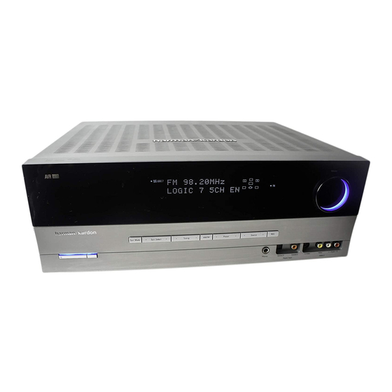
harman/kardon
AVR137/230
5 x 30W 5.1 CHANNEL A/V RECEIVER
Esd Warning..................................2
Leakage Testing............................3
Basic Specifications....................4
Troubleshooting Guide...............5
Processor Reset.........................5
Package List And Parts................6
Disassembly..................................7
Released EU2008
CONTENTS
Electrical Parts List.............12
Semiconductor Pinouts.........35
Pcb Drawings.............................72
Block Diagram............................78
Wiring Diagram...........................79
AMP BIAS ADJUSTMENT................80
Schematic Diagrams...............81
harman/kardon, Inc.
250 Crossways Park Dr.
Woodbury, New York, 11797
Service Manual
Rev 0, 04/2008
Page 1 of 87
Advertisement
Table of Contents

Related Manuals for Harman Kardon AVR137


Summary of Contents for Harman Kardon AVR137
- Page 1 Service Manual AVR137/230 5 x 30W 5.1 CHANNEL A/V RECEIVER CONTENTS ESD WARNING………………………..…..2 ELECTRICAL PARTS LIST…….……12 LEAKAGE TESTING………………..…..3 SEMICONDUCTOR PINOUTS……...35 BASIC SPECIFICATIONS…………….….4 PCB DRAWINGS…………....72 TROUBLESHOOTING GUIDE….……..5 BLOCK DIAGRAM………....78 PROCESSOR RESET……………….……5 WIRING DIAGRAM…….....79 PACKAGE LIST AND PARTS……….…...6 AMP BIAS ADJUSTMENT….…..…..80 DISASSEMBLY………………………….…7...
- Page 2 AVR137/230 Service Manual Some semiconductor (solid state) devices can be damaged easily by static electricity. Such components commonly are called Electrostatically Sensitive (ES) Devices. Examples of typical ES devices are integrated circuits and some field effect transistors and semiconductor "chip" components.
- Page 3 AVR137/230 Service Manual SAFETY PRECAUTIONS The following check should be performed for the continued protection of the customer and service technician. LEAKAGE CURRENT CHECK Measure leakage current to a known earth ground (water pipe, conduit, etc.) by connecting a leakage current tester...
- Page 4 Depth measurement includes knobs, buttons and terminal connections. Height measurement includes feet and chassis. All features and specifications are subject to change without notice. Harman Kardon is a registered trademark. *Manufactured under license from Dolby Laboratories. “Dolby”, “Pro Logic”, and the Double-D symbol are trademarks of Dolby Laboratories, Inc.
- Page 5 Power switch 1 is red due to possible short and speaker ends • Amplifier is in protection mode • Contact your local Harman Kardon service depot due to internal problems No sound from surround or • Incorrect surround mode •...
- Page 6 AVR 137/230 harman/kardon AVR137/230 Service Manual 2. Package Drawing 1. Instruction manual ass'y - Accessories ACCESSORY-1 FM 1 POLE ANT POLY BAG AM LOOP ANTENNA ASS'Y BATTERY ASS'Y SNOW PAD (L) SNOW PAD (R) REMOCON IMAGE BROCHURES STAPLE TRANSMITTER ASS'Y...
- Page 7 AVR137/230 Service Manual AVR137/230 DISASSEMBLY 1. Removing the Top Cabinet 3. Removing the Rear Panel Remove the Screws Remove the Screws 16 17 4. Removing the Main PCB Remove the Screws 2. Removing the Front Panel Remove the Screws...
- Page 8 AVR137/230 Service Manual DISASSEMBLY PROCEDURES for HK AVR 137 <1> TOP-CABINET(21) REMOVAL 1. Remove 13 screws(S1,S7) and then remove the Top-cabinet. <2> FRONT PANEL ASS’Y REMOVAL 1. Remove the Top-cabinet, referring to the previous step<1>. 2. Disconnect the card cable between connector(CN72-17p) on the Fip PCB(37-1) and connector(CN72) on the Input PCB(39-1).
- Page 9 AVR137/230 Service Manual 3. Remove 2 screws(S8) and then remove the Tuner Module(42). <8>VIDEO PCB(41) REMOVAL 1. Remove the Top-cabinet, referring to the previous step<1>. 2. Disconnect the card cable between connector(BN14-13p) on the Video PCB(41) and connector(CN14) on the Input PCB(39-1).
- Page 10 AVR137/230 Service Manual 8. Disconnect connector (CN91-3P) on the Main PCB(38-1) from lead wire of the Power Trans(36) 9. Disconnect the lead wire(BN89-2P) on the Main PCB(38-1) from connector(CN89) on Regulator PCB(A)(40-2). 10. Disconnect the lead wire(BN19-3P,BN20-4P) on the Main PCB(38-1) from connector(CN19-3P,CN20-4P) on TRANS PCB(40-4).
- Page 11 AVR 137/230 EXPLODED VIEW harman/kardon AVR137/230 Service Manual 40-3 40-4 40-1 40-5 39-1 40-2 38-2 38-1 39-2 40-2 DESCRIPTION PARTS NO. Q,ty Weright ORNAMENT,VOLUME CGU1A318Z CAP,VOLUME CGX1A338MBC63 HOLDER,VOLUME CMH1A214 INDICATOR,VOLUME CGL1A222 WINDOW ASS'Y CGUAVR132/230 WINDOW,FIP CGU2A399Z BADGE,MODEL CGB1A173Z SHEET,VOLUME CMZ2A090...
- Page 12 AVR137/230 Service Manual AVR137/230 Electrical Parts List Description Value Ref. # Part Number CGB1A152Z BADGE , HARMAN/KARDON(TOP) BADGE CGL1A222 INDICATOR , VOLUME INDICATOR CGUAVR137 FRONT WINDOW ASS'Y ASS'Y CGB1A183Z BADGE , HARMAN AVR137/230 BADGE CGU2A399Y WINDOW , FIP FIP WINDOW...
- Page 13 AVR137/230 Service Manual C714 HCBS1H151KB CAP , CERAMIC 150UF 50V K C716 CCEA1AH331T CAP , ELECT 330UF 10V C719 HCBS1H102KB CAP , CERAMIC 1000PF 50V K C720 HCBS1H102KB CAP , CERAMIC 1000PF 50V K C721 HCBS1H102KB CAP , CERAMIC...
- Page 14 AVR137/230 Service Manual R704 CRD20TJ100T RES , CARBON 10 OHM 1/5W J R705 CRD20TJ820T RES , CARBON 82 OHM 1/5W J R706 CRD20TJ820T RES , CARBON 82 OHM 1/5W J R708 CRD20TJ820T RES , CARBON 82 OHM 1/5W J...
- Page 15 AVR137/230 Service Manual R912 CRD20TJ221T RES , CARBON 220 OHM 1/5W J R913 CRD20TJ102T RES , CARBON 1K OHM 1/5W J R915 CRD20TJ473T RES , CARBON 47K OHM 1/5W J R918 CRD20TJ472T RES , CARBON 4.7K OHM 1/5W J...
- Page 16 AVR137/230 Service Manual CHS1A032 TAPE , HEMELON TAPE CJA2B043ZA CORD , POWER(EUR) POWER CORD CKF8A319W PANEL , REAR AVR137/230 REAR PANEL CKL2A069H43 FOOT FOOT CLZ9W003Z FERRITE , RING FERRITE RING CMD2A487 BRACKET , TRANS BRACKET CNVM9014MS1 MODULE , TUNER(EUR)
- Page 17 AVR137/230 Service Manual C683 CCEA1HH100T CAP , ELECT 10UF 50V C684 CCEA1HH100T CAP , ELECT 10UF 50V C685 CCEA1HH100T CAP , ELECT 10UF 50V C726 CCKT1H221KB CAP , CERAMIC 220PF 50V C900 HCQI1H473JZ CAP , MYLAR 0.047UF 50V C901...
- Page 18 AVR137/230 Service Manual Q513 HVTKTC3200G KTC3200GR Q514 HVTKTC3200G KTC3200GR Q515 HVTKTC3200G KTC3200GR Q516 HVTKTC3200G KTC3200GR Q517 HVTKTC3200G KTC3200GR Q518 HVTKTC3200G KTC3200GR Q519 HVTKTC3200G KTC3200GR Q520 HVTKTC3200G KTC3200GR Q541 HVTKTC3198Y KTC3198Y Q542 HVTKTC3198Y KTC3198Y Q543 HVTKTC3198Y KTC3198Y Q544 HVTKTC3198Y KTC3198Y...
- Page 19 AVR137/230 Service Manual R532 CRD20TJ221T RES , CARBON 220 OHM 1/5W J R533 CRD20TJ221T RES , CARBON 220 OHM 1/5W J R534 CRD20TJ221T RES , CARBON 220 OHM 1/5W J R535 CRD20TJ221T RES , CARBON 220 OHM 1/5W J...
- Page 20 AVR137/230 Service Manual R632 CRD25FJ180T RES , CARBON 18 OHM 1/4W R633 CRD25FJ180T RES , CARBON 18 OHM 1/4W R634 CRD25FJ180T RES , CARBON 18 OHM 1/4W R635 CRD25FJ180T RES , CARBON 18 OHM 1/4W R636 CRD25FJ180T RES , CARBON...
- Page 21 AVR137/230 Service Manual R941 CRD20TJ223T RES , CARBON 22K OHM 1/5W J R942 CRD20TJ223T RES , CARBON 22K OHM 1/5W J R944 CRD25TJ223T RES , CARBON 22K OHM 1/4W J R946 CRD25TJ223T RES , CARBON 22K OHM 1/4W J...
- Page 22 AVR137/230 Service Manual L503 CLEY0R5KAK COIL , SPEAKER 0.5UH L504 CLEY0R5KAK COIL , SPEAKER 0.5UH L505 CLEY0R5KAK COIL , SPEAKER 0.5UH Q858 HVT2SA1360O 2SA1360O Q871 HVT2SA1360O 2SA1360O Q872 HVT2SA1360O 2SA1360O Q874 HVT2SA1360O 2SA1360O Q875 HVT2SA1360O 2SA1360O Q881 HVT2SC3423O 2SC3423O...
- Page 23 AVR137/230 Service Manual C119 CCEA1JH470T CAP , ELECT 63V/47UF/105'C C120 CCEA1JH470T CAP , ELECT 63V/47UF/105'C C121 HCBS1H103ZF CAP , CERAMIC 0.01UF 50V C123 CCFT1H473ZF CAP , CERAMIC 0.047UF 50V ZF C125 CCFT1H473ZF CAP , CERAMIC 0.047UF 50V ZF C126...
- Page 24 AVR137/230 Service Manual R109 CRD20TJ100T RES , CARBON 10 OHM 1/5W J R110 CRD20TJ4R7T RES , CARBON 4.7 OHM 1/5W J R112 CRD20TJ122T RES , CARBON 1.2K OHM 1/5W J R113 CRD20TJ473T RES , CARBON 47K OHM 1/5W J...
- Page 25 AVR137/230 Service Manual C912 CCEA0JKR322 CAP , ELECT 2200UF 6.3V C929 CCEA1VH102E CAP , ELECT 1000UF 35V C930 CCEA1VH102E CAP , ELECT 1000UF 35V C941 CCEA1CH682E CAP , ELECT 6800UF 16V D991 HVDKBU804F DIODE , BRIDGE KBU804F D992 HVDKBU804F...
- Page 26 AVR137/230 Service Manual C602 CCEA0JH102T CAP , ELECT 1000UF 6.3V C603 HCBS1H220JC CAP , CERAMIC 22PF 50V C604 CCEA0JH102T CAP , ELECT 1000UF 6.3V C605 HCBS1H220JC CAP , CERAMIC 22PF 50V C606 CCEA0JH102T CAP , ELECT 1000UF 6.3V C611...
- Page 27 AVR137/230 Service Manual C209 CCUS1H221JA CAP , CHIP 220PF C210 CCUS1H221JA CAP , CHIP 220PF C211 CCUS1H221JA CAP , CHIP 220PF C212 CCUS1H221JA CAP , CHIP 220PF C213 CCUS1H221JA CAP , CHIP 220PF C214 CCUS1H221JA CAP , CHIP 220PF...
- Page 28 AVR137/230 Service Manual C392 CCUS1H151JA CAP , CHIP 150PF C393 CCUS1H151JA CAP , CHIP 150PF C394 CCUS1H102KC CAP , CHIP 1000PF C395 CCUS1H151JA CAP , CHIP 150PF C396 CCUS1H151JA CAP , CHIP 150PF C601 CCUS1H104KC CAP , CHIP 0.1UF...
- Page 29 AVR137/230 Service Manual D208 CVD1SS355T DIODE , CHIP 1SS355T D209 CVD1SS355T DIODE , CHIP 1SS355T D210 CVD1SS355T DIODE , CHIP 1SS355T D211 CVD1SS355T DIODE , CHIP 1SS355T D212 CVD1SS355T DIODE , CHIP 1SS355T D213 CVD1SS355T DIODE , CHIP 1SS355T...
- Page 30 AVR137/230 Service Manual R206 CRJ10DJ101T RES , CHIP 100 OHM R209 CRJ10DJ101T RES , CHIP 100 OHM R210 CRJ10DJ101T RES , CHIP 100 OHM R211 CRJ10DJ101T RES , CHIP 100 OHM R212 CRJ10DJ101T RES , CHIP 100 OHM R213...
- Page 31 AVR137/230 Service Manual R305 CRJ10DJ332T RES , CHIP 3.3K OHM R306 CRJ10DJ332T RES , CHIP 3.3K OHM R307 CRJ10DJ332T RES , CHIP 3.3K OHM R308 CRJ10DJ332T RES , CHIP 3.3K OHM R309 CRJ10DJ332T RES , CHIP 3.3K OHM R310...
- Page 32 AVR137/230 Service Manual R721 CRJ10DJ330T RES , CHIP 33 OHM R723 CRJ10DJ2R7T RES , CHIP 2.7 OHM R724 CRJ10DJ101T RES , CHIP 100 OHM R725 CRJ10DJ473T RES , CHIP 47K OHM R726 CRJ10DJ473T RES , CHIP 47K OHM R727...
- Page 33 AVR137/230 Service Manual C294 CCEA1CH101T CAP , ELECT 100UF 16V C341 CCEA1HH100T CAP , ELECT 10UF 50V C342 CCEA1HH100T CAP , ELECT 10UF 50V C343 CCEA1HH100T CAP , ELECT 10UF 50V C344 CCEA1HH100T CAP , ELECT 10UF 50V C345...
- Page 34 AVR137/230 Service Manual CN17 CJP12GB142Z PIN HEADER(12PIN, 2.54mm, ANGLE) PIN HEADER CN18 CJP05GA19ZY WAFER, STRAIGHT, 5PIN WAFER CN19 CJP09GA117Z WAFER WAFER CN20 CJP05GA01ZY WAFER(YMW025-05R) WAFER CN22 CJP06GA19ZY WAFER , STRAIGHT DVD LOADER WAFER CN49 CJP05GA19ZY WAFER, STRAIGHT, 5PIN WAFER...
- Page 35 AVR137/230 Service Manual harman/kardon (70 Ω) 2SB1559 Darlington Equivalent circuit Silicon PNP Epitaxial Planar Transistor (Complement to type 2SD2389) Application : Audio, Series Regulator and General Purpose External Dimensions MT-100(TO3P) Absolute maximum ratings (Ta=25°C) Electrical Characteristics (Ta=25°C) 2SB1559 Symbol Conditions...
- Page 36 AVR137/230 Service Manual harman/kardon Equivalent circuit 2SD2389 Darlington (7 0Ω) Silicon NPN Triple Diffused Planar Transistor (Complement to type 2SB1559) Application : Audio, Series Regulator and General Purpose External Dimensions MT-100(TO3P) Absolute maximum ratings (Ta=25°C) Electrical Characteristics (Ta=25°C) Symbol 2SD2389...
- Page 37 AVR137/230 Service Manual 74ACT04 HEX INVERTER HIGH SPEED: t = 5.0ns (TYP.) at V = 5V LOW POWER DISSIPATION: = 2µA(MAX.) at T =25°C COMPATIBLE WITH TTL OUTPUTS = 2V (MIN.), V = 0.8V (MAX.) 50Ω TRANSMISSION LINE DRIVING...
- Page 38 AVR137/230 Service Manual 74ACT04 HEX INVERTER HIGH SPEED: t = 5.0ns (TYP.) at V = 5V LOW POWER DISSIPATION: = 2µA(MAX.) at T =25°C COMPATIBLE WITH TTL OUTPUTS = 2V (MIN.), V = 0.8V (MAX.) 50Ω TRANSMISSION LINE DRIVING...
- Page 39 AVR137/230 Service Manual Philips Semiconductors Product specification Hex inverter 74HCU04 PIN DESCRIPTION PIN NO. SYMBOL NAME AND FUNCTION 1, 3, 5, 9, 11, 13 1A to 6A data inputs 2, 4, 6, 8, 10, 12 1Y to 6Y data outputs...
- Page 40 AVR137/230 Service Manual ASAHI KASEI [AK4589] オーダリングガイド -10 ∼ +70°C AK4589VQ 80pin LQFP(0.5mm pitch) 評価ボード AKD4589 ピン配置 TEST1 INT1 BOUT TVDD DVDD AVSS DVSS AVDD VREFH XT I (Top View) VCOM TEST3 MCKO2 MCKO1 ROUT1+ COUT ROUT1- UOUT LOUT1+...
- Page 41 AVR137/230 Service Manual harman/kardon Page 41 of 87...
- Page 42 AVR137/230 Service Manual HCF4053B TRIPLE 2-CHANNEL ANALOG MULTIPLEXER/DEMULTIPLEXER LOW "ON" RESISTANCE : 125Ω (Typ.) OVER 15V p.p SIGNAL-INPUT RANGE FOR = 15V HIGH "OFF" RESISTANCE : CHANNEL LEAKAGE ± 100pA (Typ.) at V = 18V BINARY ADDRESS DECODING ON CHIP HIGH DEGREE OF LINEARITY : <...
- Page 43 AVR137/230 Service Manual Page 43 of 87...
- Page 44 AVR137/230 Service Manual HY57V161610E PIN CONFIGURATION DQ15 DQ15 DQ14 DQ14 VSSQ VSSQ DQ13 DQ13 DQ12 DQ12 VDDQ VDDQ DQ11 DQ11 DQ10 DQ10 VSSQ VSSQ VDDQ VDDQ 50pin TSOP II 50pin TSOP II VDDQ VDDQ 400mil x 825mil 400mil x 825mil...
- Page 45 AVR137/230 Service Manual harman/kardon Page 45 of 87...
- Page 46 AVR137/230 Service Manual Page 46 of 87...
- Page 47 L7800 SERIES harman/kardon AVR137/230 Service Manual Figure 3: Connection Diagram (top view) TO-220 (Any Type) TO-220FP/TO-220FM PAK (Any Type) TO-3 Table 3: Order Codes TO-220 TO-220 TO-220 TYPE TO-220FP TO-220FM TO-3 (C Type) (A Type) (C Type) (E Type) (A Type) (*) (T &...
- Page 48 L7800 SERIES harman/kardon AVR137/230 Service Manual Figure 3: Connection Diagram (top view) TO-220 (Any Type) TO-220FP/TO-220FM PAK (Any Type) TO-3 Table 3: Order Codes TO-220 TO-220 TO-220 TYPE TO-220FP TO-220FM TO-3 (C Type) (A Type) (C Type) (E Type) (A Type) (*) (T &...
- Page 49 L7800 SERIES harman/kardon AVR137/230 Service Manual Figure 3: Connection Diagram (top view) TO-220 (Any Type) TO-220FP/TO-220FM PAK (Any Type) TO-3 Table 3: Order Codes TO-220 TO-220 TO-220 TYPE TO-220FP TO-220FM TO-3 (C Type) (A Type) (C Type) (E Type) (A Type) (*) (T &...
- Page 50 AVR137/230 Service Manual L7900 ABSOLUTE MAXIMUM RATINGS Symbol Parameter Value Unit DC Input Voltage (for V = 5 to 18V) (for V = 20, 24V) Output Current Internally limited Power Dissipation Internally limited Operating Junction Temperature Range 0 to 150...
- Page 51 AVR137/230 Service Manual L7900 ABSOLUTE MAXIMUM RATINGS Symbol Parameter Value Unit DC Input Voltage (for V = 5 to 18V) (for V = 20, 24V) Output Current Internally limited Power Dissipation Internally limited Operating Junction Temperature Range 0 to 150...
- Page 52 AVR137/230 Service Manual LC72723, LC72723M Pin Assignment (DIP16/MFP16) Block Diagram No. 6037-2/8 Page 52 of 87...
- Page 53 AVR137/230 Service Manual 1A LOWDROP OUT VOLTAGE REGULATOR (ADJUSTABLE & FIXED) LM1117 FEATURES SOT-223 PKG (FRONT VIEW) ● Output Current up to 1 A ● Low Dropout Voltage ( 700mV at 1A Output Current ) PIN FUNCTION ● Three Terminal Adjustable or Fixed 1.5V, 1.8V, 2.5V, 2.85V, 1.
- Page 54 AVR137/230 Service Manual 1A LOWDROP OUT VOLTAGE REGULATOR (ADJUSTABLE & FIXED) LM1117 FEATURES SOT-223 PKG (FRONT VIEW) ● Output Current up to 1 A ● Low Dropout Voltage ( 700mV at 1A Output Current ) PIN FUNCTION ● Three Terminal Adjustable or Fixed 1.5V, 1.8V, 2.5V, 2.85V, 1.
- Page 55 AVR137/230 Service Manual M24C64, M24C32 SUMMARY DESCRIPTION These I C-compatible electrically erasable pro- Table 2. Signal Names grammable memory (EEPROM) devices are orga- E0, E1, E2 Chip Enable nized as 8192 x 8 bits (M24C64) and 4096 x 8 bits (M24C32).
- Page 56 AVR137/230 Service Manual M29W800DT, M29W800DB Figure 3. SO Connections Figure 4. TSOP Connections BYTE V SS DQ15A–1 DQ14 DQ13 DQ12 V CC M29W800DT M29W800DT M29W800DB DQ11 M29W800DB BYTE V SS V SS DQ10 DQ15A–1 DQ14 DQ13 DQ10 DQ12 V SS...
- Page 57 AVR137/230 Service Manual www.fairchildsemi.com MC78XX/LM78XX/MC78XXA 3-Terminal 1A Positive Voltage Regulator Features Description • Output Current up to 1A The MC78XX/LM78XX/MC78XXA series of three • Output Voltages of 5, 6, 8, 9, 10, 12, 15, 18, 24V terminal positive regulators are available in the •...
- Page 58 AVR137/230 Service Manual Page 58 of 87...
- Page 59 AVR137/230 Service Manual NJM2391 LOW DROPOUT VOLTAGE REGULATOR GENERAL DESCRIPTION PACKAGE OUTLINE The NJM2391 is low dropout voltage regulators featuring high precision voltage. It is suitable for Notebook PCs, PC cards and hard disks where 3.3V need to be generated from 5V supply.
- Page 60 AVR137/230 Service Manual NJM2595 5-INPUT 3-OUTPUT VIDEO SWITCH GENERAL DESCRIPTION PACKAGE OUTLINE The NJM2595 is a 5-input 3-output video switch. Its switches select one from five signals received from VTR,TV,DVD, TV-GAME and others. The NJM2595 is designed for audio items, such as AV amplifier and others.
- Page 61 AVR137/230 Service Manual Page 61 of 87...
- Page 62 AVR137/230 Service Manual harman/kardon Page 62 of 87...
- Page 63 AVR137/230 Service Manual harman/kardon Page 63 of 87...
- Page 64 AVR137/230 Service Manual Page 64 of 87...
- Page 65 AVR137/230 Service Manual × PIN CONFIGURATION TO-92 SOT-89 SOT-23-5 • • • (mark side) (mark side) (mark side) PIN DESCRIPTION TO-92 SOT-89 SOT-23-5 • • • Pin No Symbol Pin No Symbol Pin No Symbol Page 65 of 87...
- Page 66 AVR137/230 Service Manual × PIN CONFIGURATION TO-92 • SOT-89 SOT-23-5 • • (mark side) (mark side) (mark side) PIN DESCRIPTION TO-92 SOT-89 SOT-23-5 • • • Pin No. Symbol Pin No. Symbol Pin No. Symbol Page 66 of 87...
- Page 67 AVR137/230 Service Manual ST202E/ST232E PIN CONFIGURATION PIN DESCRIPTION PIN No SYMBOL NAME AND F UNCTION Positive Terminal for the first Charge Pump Capacitor Doubled Voltage Terminal Negative Terminal for the first Charge Pump Capacitor Positive Terminal for the second Charge Pump Capacitor...
- Page 68 AVR137/230 Service Manual Page 68 of 87...
- Page 69 AVR137/230 Service Manual Page 69 of 87...
- Page 70 AVR137/230 Service Manual harman/kardon Page 70 of 87...
- Page 71 AVR137/230 Service Manual harman/kardon Page 71 of 87...
- Page 72 AVR 137/230 harman/kardon AVR137/230 Service Manual Page 72 of 87...
- Page 73 AVR 137/230 harman/kardon AVR137/230 Service Manual Page 73 of 87...
- Page 74 AVR 137/230 harman/kardon AVR137/230 Service Manual Page 74 of 87...
- Page 75 AVR137/230 Service Manual AVR 137/230 Page 75 of 87...
- Page 76 AVR 137/230 harman/kardon AVR137/230 Service Manual Page 76 of 87...
- Page 77 AVR 137/230 harman/kardon AVR137/230 Service Manual Page 77 of 87...
- Page 78 AVR137/230 Service Manual AVR 137/230 BLOCK DIAGRAM Page 78 of 87...
- Page 79 AVR137/230 Service Manual AVR 137/230 wiring diagram Page 79 of 87...
- Page 80 AVR137/230 Service Manual AMPLIFIER SECTION BIAS ADJUSTMENT Measurement condition .No input signal or volume position is minimum. Standard value .Ideal current = 48mA (± 5%) .Ideal DC Voltage = 25.92mV (± 5%) DC EVM CUP11911Y (MAIN PCB) CN61 CN64...
- Page 81 AVR137/230 Service Manual AVR 137/230 Page 81 of 87...
- Page 82 AVR 137/230 harman/kardon AVR137/230 Service Manual Page 82 of 87...
- Page 83 AVR 137/230 harman/kardon AVR137/230 Service Manual Page 83 of 87...
- Page 84 AVR 137/230 harman/kardon AVR137/230 Service Manual Page 84 of 87...
- Page 85 AVR 137/230 harman/kardon AVR137/230 Service Manual Page 85 of 87...
- Page 86 AVR 137/230 harman/kardon AVR137/230 Service Manual Page 86 of 87...
- Page 87 AVR 137/230 harman/kardon AVR137/230 Service Manual Page 87 of 87...