Fujitsu ARU9RLF Design & Technical Manual
Hide thumbs
Also See for ARU9RLF:
- Service instruction (69 pages) ,
- Design & technical manual (319 pages) ,
- Service instructions manual (100 pages)

Related Manuals for Fujitsu ARU9RLF


Summary of Contents for Fujitsu ARU9RLF
-
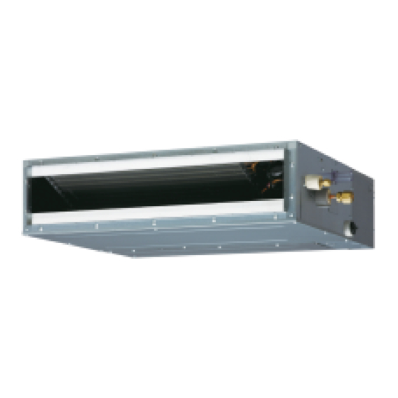
Page 1: Duct Type
AIR CONDITIONER Duct type DESIGN & TECHNICAL MANUAL INDOOR ARU9RLF ARU18RLF ARU12RLF OUTDOOR AOU9RLFC AOU12RLFC AOU18RLFC... -
Page 2: Indoor Unit
1. INDOOR UNIT DUCT TYPE : ARU9RLF ARU12RLF ARU18RLF DTR_AR059E_01 2013.02.28... -
Page 3: Table Of Contents
CONTENTS 1. INDOOR UNIT 1. FEATURES ......................01 - 01 3. SPECIFICATIONS ....................01 - 04 4. DIMENSIONS ......................01 - 05 5. WIRING DIAGRAMS ..................01 - 09 6. CAPACITY TABLE .................... 01 - 10 6-1. COOLING CAPACITY ..................01 - 10 6-2. -
Page 4: Features
FEATURES MODELS „ „ ARU9RLF / AOU9RLFC ARU9RLF ARU18RLF ARU12RLF / AOU12RLFC ARU12RLF ARU18RLF / AOU18RLFC FEATURES „ „ Energy saving „ High energy saving was realized by converting indoor unit/outdoor unit fan motors and compressor to all DC, and also by optimal design of the refrigerant cycle. -
Page 5: Wired Remote Controller
WIRED REMOTE CONTROLLER FEATURES ● Various timer setup available (ON/OFF/WEEKLY). „ „ ● Equipped with weekly timer as standard function. (Start/Stop function is twice per day for a week) ● When setting up the timer, start/stop and temperature setup can be changed. -
Page 6: Wiring Specifications
FUNCTIONS „ „ START/STOP button Pressed to start and stop operation. SET TEMP. button Selects the setting temperature. MODE button Selects the operating mode (AUTO, HEAT, FAN, COOL, DRY). FAN button Selects the fan speed (AUTO, QUIET, LOW, MED, HIGH). ECONOMY (THERMO SENSOR) button Turns the economy efficient mode on and off. -
Page 7: Specifications
SPECIFICATIONS DUCTED MODEL Type INVERTER HEAT PUMP Model name ARU9RLF ARU12RLF ARU18RLF Power source 208 / 230V ~ 60Hz Available boltage range 187 - 253V ~ 60Hz 2.64 3.52 5.28 Rated Btu/h 9,000 12,000 18,000 Cooling 0.90 - 3.60 0.90 - 4.00 0.90 - 5.90... -
Page 8: Dimensions
DIMENSIONS MODELS: ARU9RLF, ARU12RLF „ „ Unit : in. (mm) 2 (51) 22-19/32 (574) View A Rear view (Drain hose) Drain port 3-15/16 (100) x 6 = 23-5/8 (600) 1-27/32 (47) 25-19/32 (650) 2-5/32 (55) 3-1/16 (78) 28-29/32 (734) 3-1/2 (89) - Page 9 MODEL : ARU18RLF „ „ Unit : in. (mm) 2 (51) 30-15/32 (774) Rear view View A (Drain hose) Drain port 1-27/32 (47) 3-15/16 (100) x 8 = 31-1/2 (800) 2-5/32 (55) 3-1/16 (78) 33-15/32 (850) 3-1/2 (89) 36-25/32 (934) 3-7/16 (87) 4-11/16 (119) Top view...
- Page 10 INSTALLATION PLACE Unit : in. (mm) „ „ 11-13/16 (300) or more Strong and durable ceiling 25/32 (20) or more Indoor unit Left Right side side 25/32 (20) or more 11-13/16 (300) 3-15/16 (100) Service access Ceiling or more or more Floor 13/32 (10) 13/32 (10)
- Page 11 MAINTENANCE SPACE „ „ Provide a service access for inspection purposes as shown below. Do not place any wiring or illumination in the service space, as they will impede service. Unit : in. (mm) Service access Unit Control 11-13/16 (300) or more Service space - (01 - 08) -...
-
Page 12: Wiring Diagrams
WIRING DIAGRAMS MODELS : ARU9RLF, ARU12RLF, ARU18RLF „ „ - (01 - 09) -... -
Page 13: Capacity Table
CAPACITY TABLE 6-1. COOLING CAPACITY MODEL : ARU9RLF „ „ Indoor temperature °FDB °FWB °FDB 0.50 0.50 10.2 0.51 11.0 0.51 11.7 0.52 12.1 0.52 0.56 0.57 0.57 10.4 0.58 11.1 0.58 11.5 0.59 0.60 0.61 0.62 0.62 10.4 0.63 10.7... - Page 14 MODEL : ARU18RLF „ „ Indoor temperature °FDB °FWB °FDB 16.0 12.2 0.96 18.0 12.2 0.98 19.0 13.5 0.99 20.4 14.1 1.00 21.8 14.4 1.01 22.4 16.0 1.02 15.1 11.7 1.09 17.1 11.7 1.11 18.0 12.9 1.12 19.2 13.5 1.14 20.6 13.9 1.15...
-
Page 15: Heating Capacity
6-2. HEATING CAPACITY MODEL : ARU9RLF „ „ Indoor temperature °FDB °FDB °FWB 14.7 1.84 14.3 1.88 14.0 1.92 13.3 1.99 16.1 1.79 15.7 1.83 15.4 1.87 14.6 1.94 16.8 1.73 16.4 1.76 16.0 1.80 15.2 1.87 17.3 1.67 16.9 1.70... - Page 16 MODEL : ARU18RLF „ „ Indoor temperature °FDB °FDB °FWB 19.3 2.42 18.9 2.47 18.4 2.52 17.5 2.63 20.7 2.63 20.2 2.68 19.7 2.74 18.8 2.85 22.2 2.68 21.6 2.73 21.1 2.79 20.1 2.90 23.1 2.79 22.6 2.85 22.0 2.91 20.9 3.03 23.3...
-
Page 17: Fan Performance
FAN PERFORMANCE 7-1. FAN PERFORMANCE CURVE MODEL : ARU9RLF „ „ 0.44 (110) 0.40 (100) SP mode09 upper limit Hi (SP mode09) 0.36 (90) 0.32 (80) Quiet (SP mode09) 0.28 (70) SP mode09 0.24 (60) lower limit 0.20 (50) Normal SP... - Page 18 Cooling „ Capacity (400) (500) (600) (700) (800) Airflow [CFM (m /h)] Heating „ Capacity (400) (500) (600) (700) (800) Airflow [CFM (m /h)] - (01 - 15) -...
- Page 19 MODEL : ARU12RLF „ „ 0.44 (110) Hi (SP mode09) SP mode09 0.40 (100) upper limit 0.36 (90) 0.32 (80) 0.28 (70) Quiet (SP mode09) 0.24 (60) SP mode09 lower limit Normal SP 0.20 (50) upper limit Hi (Normal SP) 0.16 (40) Quiet (Normal SP)
- Page 20 Cooling „ Capacity (500) (600) (700) (800) (900) Airflow [CFM (m /h)] Heating „ Capacity (500) (600) (700) (800) (900) Airflow [CFM (m /h)] - (01 - 17) -...
- Page 21 MODEL : ARU18RLF „ „ 0.44 (110) Hi (SP mode09) SP mode09 0.40 (100) upper limit 0.36 (90) Quiet 0.32 (80) (SP mode09) 0.28 (70) SP mode09 0.24 (60) lower limit Normal SP 0.20 (50) upper limit Quiet 0.16 (40) (Normal SP) Hi (Normal SP) 0.12 (30)
- Page 22 Cooling „ Capacity (700) (800) (900) (1000) (1100) Airflow [CFM (m /h)] Heating „ Capacity (700) (800) (900) (1000) (1100) Airflow [CFM (m /h)] - (01 - 19) -...
-
Page 23: Airflow
7-2. AIRFLOW MODEL : ARU9RLF „ „ Cooling „ Number of Fan speed rotations Airflow (r.p.m.) HIGH 1260 1160 1060 QUIET Heating „ Number of Fan speed rotations Airflow (r.p.m.) HIGH 1260 1160 1060 QUIET - (01 - 20) -... - Page 24 MODEL : ARU12RLF „ „ Cooling „ Number of Fan speed rotations Airflow (r.p.m.) HIGH 1340 1240 1140 QUIET 1030 Heating „ Number of Fan speed rotations Airflow (r.p.m.) HIGH 1340 1240 1140 QUIET 1030 - (01 - 21) -...
- Page 25 MODEL : ARU18RLF „ „ Cooling „ Number of Fan speed rotations Airflow (r.p.m.) HIGH 1380 1300 1220 QUIET 1140 Heating „ Number of Fan speed rotations Airflow (r.p.m.) HIGH 1380 1300 1220 QUIET 1140 - (01 - 22) -...
-
Page 26: Operation Noise (Sound Pressure)
OPERATION NOISE (SOUND PRESSURE) 8-1. NOISE LEVEL CURVE MODEL : ARU9RLF „ „ Cooling z Heating „ N C -65 N C -65 N C -60 N C -60 N C -55 N C -55 N C -50 N C -50... - Page 27 MODEL : ARU18RLF „ „ Cooling z Heating „ N C -65 N C -65 N C -60 N C -60 N C -55 N C -55 N C -50 N C -50 N C -45 N C -45 HIGH N C -40 N C -40 HIGH...
-
Page 28: Sound Level Check Point
8-2. SOUND LEVEL CHECK POINT 6ft. 6-3/4in. (2m) 3ft. 3-3/8in. (1m) Measuring duct Measuring duct Microphone Microphone Center Center Front view Side view - (01 - 25) -... -
Page 29: Electric Characteristics
ELECTRIC CHARACTERISTICS Model name ARU9RLF ARU12RLF ARU18RLF Voltage 208/ 230 ~ Power supply Frequency Max. operating current (Indoor unit) 0.32 0.37 0.47 Connection cable *1) Wiring Spec. Limited wiring length ft. (m) 85 (26) *1) Wiring Spec. Selected Sample (Selected based on Japan Electrotechnical Standards and Codes Committee E0005) -
Page 30: Safety Devices
SAFETY DEVICES Model Protection form ARU9RLF ARU12RLF ARU18RLF Circuit protection Current fuse (PCB) 250V 3.15A OFF: 275±27°F (135±15°C) Thermal protection Fan motor protection program ON: 239±27°F (115±15°C) - (01 - 27) -... -
Page 31: External Input & Output
EXTERNAL INPUT & OUTPUT Connector INPUT OUTPUT REMARKS CN102 Control input — See external CN103 — Operation status output input/output settings for — Fresh air control output details. CN10 — Auxiliary heater output 11-1. EXTERNAL INPUT CONTROL INPUT (Operation/Stop or Forced stop) „... -
Page 32: External Output
11-2. EXTERNAL OUTPUT OPERATION STATUS OUTPUT „ „ An air conditioner operation status signal can be output. Circuit diagram example „ Indoor unit Connected unit control PC board Connector Ex.)Relay unit Ex.)Display 24V DC Relay power supply *33ft. (10m) Signal Field supply * Make the distance from the PC board to the connected unit within 33ft. - Page 33 FRESH AIR CONTROL OUTPUT „ „ A signal linked to air conditioner indoor fan ON can be output. * However, signal becomes OFF during cold air prevention control operation. Circuit diagram example „ Indoor unit Connected unit control PC board Ex.) Fan Ex.) Relay unit 12 V...
- Page 34 AUXILIARY HEATER OUTPUT „ „ A signal is outputed from Connector when indoor fan and compressor is turned on under heating operation. Tr-Ts * Signal output performance specifications are as Tr-Ts = -2°F(-1°C) shown on the right Tr-Ts = -6°F(-3°C) Ex.
-
Page 35: Function Settings
FUNCTION SETTINGS 12-1. INDOOR UNIT INDOOR UNIT DIP SW Remote controller address setting Drainage function setting Jumper Wire Setting forbidden Fan delay setting SWITCH POSITION „ „ MAIN PCB Indoor unit Printed circuit board DIP-SW SETTING „ „ Remote controller address setting „... - Page 36 JUMPER WIRE SETTING „ „ Drainage function setting (JM1) „ (u...Factory setting) Drainage function Connect Valid Disconnect Invalid Setting forbidden (JM2) „ Fan delay setting (JM3) „ (u...Factory setting) Fan delay Connect Invalid Disconnect Valid - (01 - 33) -...
-
Page 37: Indoor Unit (Setting By Remote Controller)
12-2. INDOOR UNIT (Setting by remote controller) ● The function settings of the control of the indoor unit can be changed by this procedure according to the installation conditions. Incorrect settings can cause the indoor unit to malfunction. ● After the power is turned on, perform the Function Setting according to the installation conditions using the remote controller. - Page 38 (5) Press the TIMER SET button to confirm the setting. Press the TIMER SET button for a few seconds until the setting value stops flashing. If the setting value display changes or if “- -” is displayed when the flashing stops, the setting value has not been set correctly. (An invalid setting value may have been selected for the indoor unit.) (6) Repeat steps 2 to 5 to perform additional settings.
- Page 39 CONTENTS OF FUNCTION SETTING „ „ • Follow the instructions in the Local Setup Procedure, which is supplied with the remote controller, in accordance with the installed condition. After the power is turned on, perform the Function Setting on the remote controller. •...
- Page 40 4) Heater room temperature correction Depending on the installed environment, the room temperature sensor may require a correction. The settings may be changed as shown in the table below. ( ... Factory setting) Setting description Function number Setting value Standard ...
-
Page 41: Wired Remote Controller
12-3. WIRED REMOTE CONTROLLER Forbidden Dual remote controller setting Forbidden Switch 1 °F / °C switch Forbidden Memory backup setting * Do not use DIP Switch 2 SWITCH POSITION „ „ Wired remote controller „ Front case (back side) DIP Switch 2 DIP Switch 1 (All switches fixed at OFF) - Page 42 DIP SWITCH 1 SETTING „ „ SW1 setting forbidden „ (u...Factory setting) Fixed at OFF Setting forbidden SW2 setting „ ● Dual remote controller setting Set the remote controller SW2 according to the following table. Indoor unit (u...Factory setting) Secondary Primary unit Number Remote controller cable...
- Page 43 SW5 setting forbidden „ (u...Factory setting) Fixed at OFF Setting forbidden SW6 setting „ ● Memory backup setting (Wired remote controller only) Set to ON to use batteries for the memory backup. If batteries are not used, all of settings stored in memory will be deleted if there is a power failure.
-
Page 44: Optional Parts
OPTIONAL PARTS 13-1. CONTROLLERS Exterior Parts name Model No. Summary Monitor Mo 10:00AM Large and full-dot liquid Mode Set temp. Wired remote crystal screen, wide and ° F Cool High UTY-RVNUM Icon check: large keys easy to press, Menu controller user-intuitive arrow key. -
Page 45: Outdoor Unit
2. OUTDOOR UNIT SINGLE TYPE : AOU9RLFC AOU12RLFC AOU18RLFC DTR_AO131E_01 2013.02.28... - Page 46 CONTENTS 2. OUTDOOR UNIT 1. SPECIFICATIONS ....................02 - 01 2. DIMENSIONS ......................02 - 02 3. REFRIGERANT CIRCUIT ................02 - 03 4. WIRING DIAGRAMS ..................02 - 04 5. CAPACITY COMPENSATION RATE FOR PIPE LENGTH AND HEIGHT DIFFERENCE ..............
-
Page 47: Specifications
SPECIFICATIONS Type INVERTER HEAT PUMP Model name AOU9RLFC AOU12RLFC AOU18RLFC Power source 208 / 230V 60Hz Available voltage range 187 - 253V 60Hz Starting current [ARU18RLF] 1206 (2050) Cooling 794 (1350) 1206 (2050) Airflow [AUU18RLF] rate 1457 (2475) Heating 989 (1680) 1083 (1840) 1407 (2355) Type ×... -
Page 48: Dimensions
DIMENSIONS MODEL : AOU9RLFC, AOU12RLFC, AOU18RLFC „ „ Unit : in. (mm) 21-1/4 (540) Air flow 8-7/32 (209) Drain pipe 4-Ø7/16 (11.3) hole mounting place (Ø25/32 (20)) Bottom view INSTALLATION PLACE „ „ When there are obstacles at When there are obstacles at When there are obstacles at the the back or front sides. -
Page 49: Refrigerant Circuit
REFRIGERANT CIRCUIT MODEL : AOU9RLFC, AOU12RLFC, AOU18RLFC „ „ Heat exchanger 3-Way ( INDOOR ) valve 2-Way valve Muffler 4-Way valve Strainer Expansion valve Heat exchanger Strainer ( OUTDOOR ) Cooling Heating : Thermistor (Discharge Temp.) : Thermistor (Outdoor Temp.) : Thermistor (Heat Exchanger Out Temp.) : Thermistor (Room Temp.) : Thermistor (Pipe Temp.) -
Page 50: Wiring Diagrams
WIRING DIAGRAMS MODEL : AOU9RLFC, AOU12RLFC „ „ - (02 - 04) -... - Page 51 MODEL : AOU18RLFC „ „ - (02 - 05) -...
-
Page 52: Capacity Compensation Rate For Pipe Length
CAPACITY COMPENSATION RATE FOR PIPE LENGTH AND HEIGHT DIFFERENCE MODEL : AOU9RLFC, AOU12RLFC „ „ Pipe length COOLING 7.5m 17ft. 25ft. 33ft. 50ft. 67ft. 50ft. 0.877 0.874 Û 1 33ft. 0.956 0.891 0.888 Indoor unit is higher than 7.5m 25ft. 0.988 0.960 0.895... - Page 53 MODEL : AOU18RLFC „ „ Pipe length COOLING 7.5m 17ft. 25ft. 33ft. 50ft. 67ft. 50ft. 0.951 0.950 Û 1 33ft. 0.979 0.967 0.966 Indoor unit is higher than 7.5m 25ft. 0.988 0.983 0.971 0.970 outdoor unit. 17ft. 0.994 0.992 0.987 0.975 0.974 Height...
-
Page 54: Additional Charge Calculation
ADDITIONAL CHARGE CALCULATION MODEL : AOU9RLFC, AOU12RLFC „ „ Refrigerant type R410A lbs. oz. 2lbs.10oz. Refrigerant amount 1200 Refrigerant Charge „ 49 or less 66 (MAX) Total Pipe length 15 or less 20 (MAX) 0.22oz./ft. (20g/m) Additional charge MODEL : AOU18RLFC „... -
Page 55: Airflow
AIRFLOW MODEL : AOU9RLFC „ „ Cooling „ Number of rotations Airflow (r.p.m.) 1350 Heating „ Number of rotations Airflow (r.p.m.) 1680 MODEL : AOU12RLFC „ „ Cooling „ Number of rotations Airflow (r.p.m.) 2050 1206 Heating „ Number of rotations Airflow (r.p.m.) - Page 56 MODEL : AOU18RLFC/ARU18RLF „ „ Cooling „ Number of rotations Airflow (r.p.m.) 2050 1206 Heating „ Number of rotations Airflow (r.p.m.) 2355 1000 1386 MODEL : AOU18RLFC/AUU18RLF „ „ Cooling „ Number of rotations Airflow (r.p.m.) 2475 1050 1457 Heating „...
-
Page 57: Operation Noise (Sound Pressure)
OPERATION NOISE (SOUND PRESSURE) 8-1. NOISE LEVEL CURVE MODEL : AOU9RLFC „ „ Cooling Heating „ „ NC-65 NC-65 NC-60 NC-60 NC-55 NC-55 NC-50 NC-50 NC-45 NC-45 NC-40 NC-40 NC-35 NC-35 NC-30 NC-30 NC-25 NC-25 NC-20 NC-20 NC-15 NC-15 1,000 2,000 4,000 8,000... - Page 58 MODEL : AOU18RLFC/ARU18RLF „ „ Cooling Heating „ „ NC-65 NC-65 NC-60 NC-60 NC-55 NC-55 NC-50 NC-50 NC-45 NC-45 NC-40 NC-40 NC-35 NC-35 NC-30 NC-30 NC-25 NC-25 NC-20 NC-20 NC-15 NC-15 1,000 2,000 4,000 8,000 1,000 2,000 4,000 8,000 Octave band center frequency,Hz Octave band center frequency,Hz MODEL : AOU18RLFC/AUU18RLF...
-
Page 59: Sound Level Check Point
8-2. SOUND LEVEL CHECK POINT Airflow Microphone Microphone 39-3/8in. (1m) - (02 - 13) -... -
Page 60: Electric Characteristics
ELECTRIC CHARACTERISTICS Model name AOU9RLFC AOU12RLFC AOU18RLFC Voltage 208 / 230 ~ Power supply Frequency 13.4 17.3 Starting Current MAX CKT BKR *1) Wiring Spec. Power Cable *2) Limited wiring length ft. (m) 60 (18) 75 (22) *1) Wiring Spec.: Selected Sample (Selected based on Japan Electrotechnical Standards and Codes Committee E0005) *2) Limited wiring length :... -
Page 61: Safety Devices
SAFETY DEVICES Model Protection form AOU9RLFC AOU12RLFC AOU18RLFC 250V 20A Current fuse 250V 25A (Near the terminal) 250V 5A Circuit protection 250V 15A 250V 10A Current fuse (Main printed circuit board) 250V 3.15A Thermal protection OFF : 212±27 °F (100±15 °C) Fan motor protection program ON : 203±18 °F (95±10 °C)