Table of Contents
Advertisement
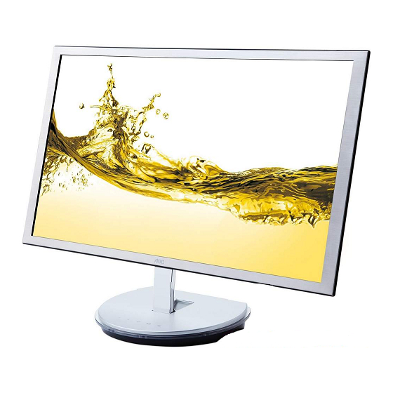
23" LCD Color Monitor
Service
Service
Service
Description
Table of Contents.........................................................1
Revision List................................................................2
Important Safety Notice...............................................3
1.Monitor Specification.................................................4
2.LCD Monitor Description.......................................5
3.Operation Instruction...............................................6
3.1.General Instructions.................................................6
3.2.Hot Keys......................................................6
3.3.OSD Setting.......................................................7
4.Input/Output Specification.......................................20
4.1.Input Signal Connector.........................................20
4.2.Factory Preset Display Modes...............................21
4.3.Panel Specification.............................................22
ANY PERSON ATTEMPTING TO SERVICE THIS CHASSIS MUST FAMILIARIZE HIMSELF WITH THE CHASSIS
AND BE AWARE OF THE NECESSARY SAFETY PRECAUTIONS TO BE USED WHEN SERVICING
ELECTRONIC EQUIPMENT CONTAINING HIGH VOLTAGES.
CAUTION: USE A SEPARATE ISOLATION TRANSFOMER FOR THIS UNIT WHEN SERVICING
Table of Contents
Page
Description
5.Block Diagram............................................25
6.Schematic.......................................................26
6.1.Main Board....................................................26
6.2.Key Board......................................................33
7.PCB Layout.....................................................34
7.1.Main Board....................................................34
7.2.Key Board....................................................35
8.Maintainability..................................................36
8.1.Equipments and Tools Requirement...............36
8.2.Trouble Shooting.........................................37
9.White-Balance, Luminance Adjustment.............41
10.Monitor Exploded View.................................43
11.BOM List..................................................45
SAFETY NOTICE
AOC i2353Ph I2353Fh
Horizontal Frequency
30-83 KHz
Page
Advertisement
Table of Contents

Related Manuals for AOC I2353Fh


Summary of Contents for AOC I2353Fh
-
Page 1: Table Of Contents
23" LCD Color Monitor AOC i2353Ph I2353Fh Service Service Service Horizontal Frequency 30-83 KHz Table of Contents Description Page Description Page 5.Block Diagram……..…………....25 Table of Contents..……......……..1 6.Schematic……………........26 Revision List.…........…………..2 6.1.Main Board………...........26 Important Safety Notice.……......……..3 6.2.Key Board...……..........33 1.Monitor Specification......………..4 7.PCB Layout..…………........34 2.LCD Monitor Description……………………………..5... -
Page 2: Revision List
Revision List Version Release Date Revision History L&T Model Name HDBJNZ2LB7IGDNF.LF HDBJNZ2FB7UMDNF.LF Jun-20-2011 Initial Release HDBJNZ2MB75ADNF.LF HDBJNZ2CBMAODNF.LF HDBJNZ2MB7RODNF.LF Sep-11-2011 Add new model HDBJNZ2CBM8ADNF.LF HDBJNZ2ABMPMDNF.LF HDBJNZ2BBMK2DNF.LF Oct-27-2011 Add new model HDBJNZ2KBME6DNF.LF HDBJNZ2CB7SPDNF.LF HDBJNZ2TBM1RDNF.LF Nov-7-2011 Add new model HDBJNZ2EB77ADNF.LF HDBJNZ2CBMSUDNF.LF HDBJNZ2CBMETDNF.LF Jan-30-2012 Add new model HDBJNZ2BBMK5DNF.LF HDBJNZ2EB7GHDNF.LF... -
Page 3: Important Safety Notice
Important Safety Notice Proper service and repair is important to the safe, reliable operation of all AOC Company Equipment. The service procedures recommended by AOC and described in this service manual are effective methods of performing service operations. Some of these service operations require the use of tools specially designed for the purpose. The special tools should be used when and as recommended. -
Page 4: Monitor Specification
1. Monitor Specifications Model number i2353Ph/ I2353Fh Driving system TFT Color LED IPS Viewable Image Size 584.2mm diagoanl Pixel pitch 0.265mm(H) x 0.265mm(V) Panel Video R, G, B Analog lnterface & Digital Interface Separate Sync. H/V TTL Display Color 16.7M Colors... -
Page 5: Lcd Monitor Description
2. LCD Monitor Description The LCD MONITOR will contain a main board,a key and two speakers board which house the flat panel control logic, brightness control logic and DDC. Monitor Block Diagram Flat Panel and LED Drive. LED backlight Key Board Main Board Speaker HDMI... -
Page 6: Operation Instruction
3. Operating Instructions 3.1 General Instructions Press the power button to turn the monitor on or off. The other control knobs are located at front panel of the monitor. By changing these settings, the picture can be adjusted to your personal preferences. 3.2 Hotkeys Power Press the Power button to turn 0n/off the monitor. -
Page 7: Osd Setting
3.3 OSD Setting Basic and simple instruction on the control keys. Press the MENU-button to activate the OSD window. 2) Press < or > to navigate through the functions. Once the desired function is highlighted, press the MENU-button to activate sub-menu . Once the desired function is highlighted, press MENU-button to activate Press to change the settings of the selected function. - Page 8 Luminance Press (Menu) to display menu Press to select (Luminance), and press to enter Press to select submenu, and press to enter.
- Page 9 Press to adjust Press to exit...
-
Page 10: Image Setup
Image Setup Press (Menu) to display menu Press to select (Image Setup) , and press to enter. Press to select submenu, and press to enter. - Page 11 Press to adjust. Press to exit Clock 0-100 Adjust picture Clock to reduce Vertical-Line noise. Phase 0-100 Adjust Picture Phase to reduce Horizontal-Line noise Sharpness 0-100 Adjust picture sharpness H.Position 0-100 Adjust the horizontal position of the picture. V.Position 0-100 Adjust the vertical position of the picture.
- Page 12 Press (Menu) to display menu. Press to select (Color Setup), and press to enter. Press to select submenu, and press to enter. Press to adjust.
- Page 13 Press to exit Warm Recall Warm Color Temperature from EEPROM. Normal Recall Normal Color Temperature from EEPROM. Cool Recall Cool Color Temperature from EEPROM. Color setup. sRGB Recall SRGB Color Temperature from EEPROM. Red Gain from Digital-register User Green Green Gain Digital-register. Blue Blue Gain from Digital-register Full...
- Page 14 Press to select (Picture Boost), and press to enter. Press to select submenu, and press to enter. Press to adjust.
- Page 15 Press to exit Frame Size 14-100 Adjust Frame Size Brightness 0-100 Adjust Frame Brightness Contras 0-100 Adjust Frame Contrast H. position 0-100 Adjust Frame horizontal Position V.position 0-100 Adjust Frame vertical Position Bright Frame on or off Disable or Enable Bright Frame OSD Setup Press (Menu) to display menu.
- Page 16 Press to select (OSD Setup), and press to enter. Press to select submenu, and press to enter. Press to adjust.
- Page 17 Press to exit H.Position 0-100 Adjust the horizontal position of OSD V.Position 0-100 Adjust the vertical position of OSD Timeout 5-120 Adjust the OSD Timeout Transparence 0-100 Adjust the transparence of OSD Language Select the OSD language Extra Press (Menu) to display menu. Press to select (Extra), and press...
- Page 18 Press to select submenu, and press to enter. Press to adjust. Press to exit...
- Page 19 Input Select Analog Select Analog Signal Source as Input Auto Config yes or no Auto adjust the picture to default Off timer 0-24hrs Select DC off time Image Ratio wide or 4:3 Select wide Select wide or 4:3 format for display DDC-CI yes or no Turn ON/OFF DDC-CI Support...
-
Page 20: Input/Output Specification
4. Input/Output Specification 4.1 D-SUB CONNECTORS and DVI CONNECTORS Pin Assignments 15-Pin Side of the Signal Cable Pin Number Pin Number 15-Pin Side of the Signal Cable Video-Red Video-Green Ground N.C. Video-Blue N.C. DDC- Serial data Detect Cable sync GND-R sync GND-G DDC-... -
Page 21: Factory Preset Display Modes
4.2 Factory Preset Display Modes... -
Page 22: Panel Specification
4.3 Panel Specification 4.3.1 General Features BM230WF3-SJC1 is a Color Active Matrix Liquid Crystal Display with an integral Light Emitting Diode (LED) backlight system. The matrix employs a-Si Thin Film Transistor as the active element. It is a transmissive type display operating in the normally black mode. - Page 23 4.3.3 Electrical Characteristics Ta = 25°C Values Parameter Symbol Unit MODULE : Power Supply Input Voltage Permissive Power Input Ripple (60Hz) LCD-MOSAIC Power Supply Input Current (60Hz) 1180 LCD-BLACK (75Hz) 1360 LCD-BLACK Power Consumption Watt Inrush current RUSH LED bar Electrical characteristics Values Parameter Symbol...
- Page 24 4.3.4 Optical Characteristics (Ta= 25°C, V =5.0V, fv=60Hz, D = 77.0MHz, Is=60mA) Values Parameter Symbol Units Contrast Ratio 1000 Surface Luminance, white cd/m Luminance Variation WHITE Gray To Gray GTG_AVR Response Time Gray To Gray G to G (BW) (BW) 0.638 0.330...
-
Page 25: Block Diagram
5. Block Diagram 5.1 Main Board CRYSTAL 12MHZ Panel Interface (X401) (CN409) Speaker (CN602) Flash Memory MX25L2026DM1I-1 Audio decoder Scalar IC NT68677UMFG/E 2G (U402) PAM8602MNHR (Include ADC, OSD, MCU) (U601) (U401) Key Control Interface (CN401) PHONE JACK D-Sub Connector HDMI Connector HDMI Connector (CN601) (CN101) -
Page 26: Schematic
6. Schematic 6.1 Main Board 715G4810M0E000004L R121 0.05R R102 C102 47N16V RIN 5 CN101 DB15 R122 0.05R R103 C103 47N16V GIN 5 RED+ RED- GREEN+ R123 0.05R R104 C104 47N16V BIN 5 GREEN- BLUE+ BLUE- VGA5V R107 C107 47N16V GNDR 5 R108 C108 47N16V GNDG 5... - Page 27 CN501 SHELL1 SHDMI1/D2+ R501 0.05R RX2+ D2 Shield SHDMI1/D2- R502 0.05R SHELL3 RX2- SHDMI1/D1+ R503 0.05R RX1+ D1 Shield SHDMI1/D1- R504 0.05R RX1- SHDMI1/D0+ R505 0.05R RX0+ D0 Shield SHDMI1/D0- R506 0.05R RX0- SHDMI1/CK+ R507 0.05R RXC+ HDMI2_DET R508 100R CK Shield DET_HDMI2 SHDMI1/CK-...
- Page 28 PA[0..9] PA[0..9] PA0 LVA3P PA1 LVA3M PA2 LVACKP CN409 PA3 LVACKM PA4 LVA2P DVDD PA5 LVA2M DVDD PA6 LVA1P PA7 LVA1M LVB0M RXO0- RXO0+ LVB0P PA8 LVA0P LVB1M RXO1- RXO1+ LVB1P PA9 LVA0M LVB2M RXO2- RXO2+ LVB2P LVBCKM RXOC- RXOC+ LVBCKP R406 LVB3M...
- Page 29 +12V +12V D601 LL4148 CN601 R601 C628 470nF 16V AINL +5V_AUDIO R602 R606 C629 470nF 16V AINR R605 PHONEJACK FB605 120 OHM R608 Q603 C609 NC/10K1/16W LMBT3906LT1G 10uF 25V +5V_AUDIO R615 470R 1/16W 5% MUTE AUDIO_MUTE CN602 Q604 R618 C635 R609 LMBT3904LT1G R607...
- Page 30 U702 G1117-33T43UF SOT 252 CMVCC1 D707 SR34 D708 SR34 VCC3.3 U701 NC/G1117-33T63Uf SOT 223 C708 C709 C707 100N 16V 100N 16V 22uF 10V CMVCC1 VCC3.3 VCC3.3 R702 R703 BKLT-EN BKLT-EN U704 D703 G1117-18T63Uf Q701 SR34 LMBT3904LT1G C702 SOT 223 on_BACKLIGHT 5 NC/100N 16V R704 22K D704...
- Page 31 CVDD DVDD DVI_VCC VCC3.3 FB401 VCC3.3 DVDD AUDIO_VDD FB402 C407 C409 ADC_VDD A_VCC 120 OHM 100N 16V 100N 16V R402 R403 3,4,8 VCC3.3 DVI_VCC MVDD 100K 100K C402 120 OHM ADC_1V8 DVDD MVDD 10uF 10V C405 DET_HDMI2 C403 C404 10uF 10V DET_HDMI2 4 DET_HDMI1 100N 16V...
- Page 32 +12V D801 L801 +12V 47UH R804 C801 C814 BR310 100N 50V 180uF 16V C810 R814 10 OHM 1/4W Q801 0.47UF 50V R801 C809 AOD482 R815 BKLT-EN C811 R802 C808 33UF 100V 160K 1% R805 300K C802 0.47UF 50V 10nF 50V C817 U801 100K 1/10W 5%...
-
Page 33: Key Board
CIN_05 MENU Auto Power T P V ( Top Victory Electronics Co . , Ltd. ) OEM MODEL AOC i2353Fh Size 715G4828-K0C-000-004S-110311 TPV MODEL 絬 隔 瓜 絪 腹 i2353Fh Key Component 2.0 Touch key PCB NAME 715G4828-K0C <称爹> 称 爹... -
Page 34: Pcb Layout
7. PCB Layout 7.1 Main Board 715G4981M0E000004L... -
Page 35: Key Board
7.2 Key Board 715G4828K0D000004M... -
Page 36: Maintainability
8. Maintainability 8.1 Equipments and Tools Requirement Voltmeter. Oscilloscope. Pattern Generator. DDC Tool with an IBM Compatible Computer. Alignment Tool. LCD Color Analyzer. Service Manual. User Manual. -
Page 37: Trouble Shooting
8.2 Trouble Shooting No Power No power Check power cable is Re-plug the power cable tightened? Check Power “On/Off” Turn on the Power “On/Off” switch is “On”? Check the LED Check the AC power indicate is OK? Replace main board and check connections Replace key board and check connections... - Page 38 2. No Video (Power LED White) No Video (Power LED White) Press the power Replace the main board button is OK? Replace the main The end board and connection Check the LVDS/FFC Replace the LVDS/FFC cable or panel cable or panel Replace the key board...
- Page 39 3. DIM DIM (image overlap, focus or flicker) Reset in factory mode The end Set to the optimal The end frequency, select the recommended frequency Readjust the phase and pixel The end clock in the user mode Pull out signal cable and Check the signal cable check “Self Test Feature and the PC...
- Page 40 4. Color is not optimal Color is not optimal Color shift Miss color Reset the factory mode Replace the signal cable In the user mode, set the” color settings” until customer satisfy The end Pull out the signal cable and check the screen color display is normal? Replace the signal cable or PC Replace the main board...
-
Page 41: White-Balance, Luminance Adjustment
9. White- Balance, Luminance Adjustment Approximately 30 minutes should be allowed for warm up before proceeding white balance adjustment. How to setting MEM channel you can reference to chroma 7120 user guide or simpl use “SC” key and “NEXT” Key to modify xyY value and use “ID”... - Page 42 C. Adjust Cool (9300K) color-temperature 1. Switch the Chroma-7120 to RGB-Mode (with press “MODE” button) 2. Switch the MEM. Channel to Channel 9 (with up or down arrow on chroma 7120) 3. The LCD-indicator on chroma 7120 will show x = 283 ±30, y = 297 ±30 4.
-
Page 43: Monitor Exploded View
10. Monitor Exploded View... - Page 44 Description BEZEL BRACKET REAR COVER RUBBER FRONTSTAND HINGE BACK STAND TOP BASE LENS BASEDECO BOTTOM BASE MAIN_FRAME SHIELDING Part No. Description MAYLAR 0M1G3030--5-47-CR3 SCREW(BRACKET/PANEL) RUBBER BEZEL 0M1G-130--5225 SCREW(HINGE/BRACKET) TAPE DOUBLE 0M1G1730--6120 SCREW(MAIN BOARD/MAIN FRAME) FOOT 0M1G-140--8125 SCREW(MAINFRAME/HINGE) PANEL 0Q1G-140-10120 SCREW(MAINFRAME/BASEDECO)
-
Page 45: Bom List
0M1G1730--6120 SCREW,42-D020523 0M1G3030--5-47-CR3 SCREW 0Q1G-140-10120 SCREW 708GDF06XWP-1A Wooden pallet Ass'y Q45G--77--5 PE PACKING (Y1900241) Q50G---4-10 TIE (Y1900221) Q52G---1185-99 big carton tape for aoc 750GBT230W3C11N000 BM230WF3-SJC1-8F1-A0 2436L-2298A BM230WF3-SJC1 3850L-0088A ID, YUPO, 78X37 6060L-2391A LM230WF3-SJC1-831 6091L-1758A BM230WF3-SJC1 3022L-1570A KOLON, XC210, T=0.123, BM230WF3-SJC1 KOLON, LE303, T=0.230, Angle = 4?,... - Page 46 7250L-1769A Ti-15, 526.0*3.9*0.25 7250L-0864A NITTO, NITTO 5000NS, Clear, 30*3*0.16 7250L-1488B Conductive Tape, STN1026W(P),15*25,T=0.11 -756GFBCB-AA006--00 MCU ASS'Y IC FLASH MX25L2026DM1I-12G 2Mb SOP-8 056G2233501 MXIC 100GANJD003FT1 AOC IPS 2353 A15G1685101 MAIN_FRAME A15G1686101 BRACKET A15G1687101 bezel A34G2661AEDA1B0100 rear cover A34G2665-Q1A1B0130 top base A34G2666--1-1C0100...
- Page 47 033G3802-7B--Y---L WAFER 7P 2.0MM XIANGLONG 2nd source 040G-45762412B CBPC LABEL C809 067G-415330-9L EC 33UF 20% 100V RZW 8*11.5 067G-415330-9K EC 33UF 20% 100V ED 8*12 2nd source C718,C801 067G204V181-3K CS CAP 180uF 16V 8*8 mm F67G204V181-3L 180uF -20% 16V 105 2000H 8*8 2nd source ℃...
- Page 48 R425,R432,R442,R4 51,R501,R502,R503, R504,R505,R506,R5 TEST ONLY RST 0402 0.05R MAX 1/16W 07,R509,R510,R518, 061G0402000-JI TA-I R519,R520,R521,R5 22,R523,R524,R526, R527 R102,R103,R104,R5 061G0402100-JI TEST ONLY RST 0402 10R 5% 1/16W TA-I 15,R533 R110,R112,R113,R4 14,R415,R417,R440, 061G0402101-JI bEST ONLY RST 0402 100R 5% 1/16W TA-I R447,R448,R508,R5 25,R616,R706 R124,R511,R529,R5 061G0402102-JI TEST ONLY RST 0402 1K 5% 1/16W TA-I...
- Page 49 R116,R117,R303,R4 05,R406,R437,R443, 061G0402472-JI TEST ONLY RST CHIP 4.7K 5% 1/16W TA-I R512,R513,R530,R5 31,R705 R101,R105,R106 061G0402750-JI TEST ONLY RST 0402 75R 5% 1/16W TA-I R808 061G0603000-JF RST CHIPR MAX 0R05 1/10W FENGHUA R111,R441,R444,R6 TEST ONLY RST 0603 0.05R MAX 1/16W 061G0603000-JI TA-I R807 061G0603100--Y...
- Page 50 C111,C112,C633,C7 065G040222031J---A MLCC 0402 22pF +-5% 50V NPO SAMSUNG MLCC 0402 220pF +-5% 50V NPO TAIYO C437,C438 065G040222131J---T YUDEN C604,C722 065G040222232K---Y MLCC 0402 2.2nF +-10% 50V X7R YAGEO C115,C303,C424,C5 MLCC 0402 0.22uF +-10% 16V X5R TAIYO 065G040222415K---T 01,C504 YUDEN C427,C428 065G040247031J---Y MLCC 0402 47pF +-5% 50V NPO YAGEO C607,C608...
- Page 51 C611,C612,C628,C6 MLCC 0603 0.47uF +-10% 16V X7R 065G060347412K---A SAMSUNG C402,C405,C412,C4 14,C416,C419,C420, 065G0805106A5K---A MLCC 0805 10uF +-10% 10V X5R SAMSUNG C425,C436,C616,C6 MLCC 0805 0.47uF +-10% 50V X7R TAIYO C804,C810,C811 065G080547432K---T YUDEN MLCC 0805 0.47uF -10% 50V X7R 065G080547432K---A 2nd source SAMSUNG MLCC 1206 10uF +-10% 25V X5R TAIYO C601,C609,C720 065G120610625K---T...
- Page 52 093G-39S-38--T PTZ9.1B ROHM 2nd source ZD603,ZD702 093G-39S957--T ZENER RLZ6V2BSG 6.2V 0.5W LL-34 D801 093G-60S509--T SCHOTTKY BR310 T/R 3A 100V SMB D601 093G-64S522SEM LL4148 D602,D701,D703,D7 093G3004--2 SR34 PAN JIT 04,D707,D708 CN803 311GF050J10ACH FFC CONN 0.5mm 10P F0503WV-S-10P E715 715G4981M0E000004L MAIN Board FR-4 94V-0 146x115*1.6MM 715G4981M0E000004F MAIN Board FR-4 94V-0 146x115*1.6MM 2nd source...
- Page 53 RST CHIPR 4.7KOHM -5% 1/16W 061G0402472-JF 2nd source FENGHUA C008 065G040210131J---Y MLCC 0402 100pF +-5% 50V NPO YAGEO C005,C006,C007 065G040210412K---A MLCC 0402 0.1uF +-10% 16V X7R SAMSUNG MLCC 0402 0.1uF -10% 16V X7R TAIYO 065G040210412K---T 2nd source YUDEN C011 065G0402105A5K---A MLCC 0402 1uF +-10% 10V X5R SAMSUNG MLCC 0402 1uF -10% 10V X5R TAIYO 065G0402105A5K---T...