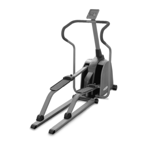
Vision Fitness X6100 Assembly Instructions Manual
Hide thumbs
Also See for X6100:
- Owner's manual (72 pages) ,
- Assembly manual (10 pages) ,
- Assembly instructions manual (10 pages)
Advertisement
Quick Links
Download this manual
See also:
Owner's Manual
X6100/6200
ASSEMBLY INSTRUCTIONS
To avoid possible damage to this Elliptical Trainer,
please follow these assembly instructions.
Carefully remove all its parts from the box,
lay them out and review the parts list.
If any parts are missing, please call 1-800-335-4348, Ext 12
Before proceeding, find your Elliptical Trainer's serial number,
located on the frame between the folding pedal arm
guide rails, and enter here:
______________________________
Refer to this number when calling for service.
A62.2
I T
A L L
S T A R T S
W I T H
A
V I S I O N
Advertisement

Related Manuals for Vision Fitness X6100


Summary of Contents for Vision Fitness X6100
-
Page 1: Assembly Instructions
X6100/6200 ASSEMBLY INSTRUCTIONS To avoid possible damage to this Elliptical Trainer, please follow these assembly instructions. Carefully remove all its parts from the box, lay them out and review the parts list. If any parts are missing, please call 1-800-335-4348, Ext 12 Before proceeding, find your Elliptical Trainer’s serial number,... - Page 2 X6100/6200 Parts Diagram Page 2...
- Page 3 Console #162 Console Attachment Bolts 11mm L x 5mm D Other Parts #207 Power Supply (Model X6200 only) Additional Parts - Model X6100 only #220 Upper Magnet Shift Cable Lower Magnet Shift Cable #225 Indexed Mast Cover RPM Sensor Wire...
- Page 4 NOTE: During each assembly step, ensure that ALL nuts and bolts are in place and partially threaded in before completely tightening any ONE bolt. NOTE: Always read the Owner’s Manual before operating your Vision Fitness Elliptical Trainer. Step 1 • Rear Wheel & Guide Rail Assembly - All Models 1: Slide the Rear Foot Axle (96) through the Rear Foot Nylon Sleeves (98).
- Page 5 X6100/6200 Assembly Step 2 • Pedal Arm Assembly - All Models 1: Slide the rear half of the Right Pedal Arm (64) into the front half of the Right Pedal Arm (61) and secure using the two Pedal Arm Attachment Bolts (173) and the two Pedal Arm Attachment Nuts (164).
- Page 6 Now slide the Rubber Console Mast Cover (88) back down to cover the bolt heads. NOTE: Assembly Step 4 refers to Models X6200/ X6200HRC only. For Model X6100 proceed to Step 5 for Handrail installation. Step 4 • Console Mast - Models X6200/ X6200HRC only.
- Page 7 X6100/6200 Assembly Step 5 • Handrail Assembly - All Models 1: Locate the Left Lower Hand Rail (79) and Left Upper Hand Rail (76). 2: Insert the Left Upper Hand Rail (76) into the Upper Hand Rail Support located on the Console Mast just below the Console.
- Page 8 X6100 Operation NOTE: Assembly Steps 6, 7, and 8 refer to Model X6100 only. For Models X6200/ X6200HRC proceed to Step 9 for Console installation. Step 6 • Console - Model X6100 only 1: Insert Upper Magnet Shift Cable (220) into the top of the Console Mast (9).
- Page 9 X6200 Operation NOTE: Assembly Steps 9, 10 and 11 refer to Models X6200/ X6200HRC only. For Model X6100 proceed to Step 12 for folding instructions. Step 9 • Console - Models X6200/ X6200HRC only. 1: Plug the Console Cable (108) into the Console (15). The cable Connectors are slotted and will only fit properly one way.
- Page 10 2: You will get the best results if you wear the transmitter directly against your skin. Once these electrodes are moistened, center the transmitter just below the breast or pectoral muscles with the Vision Fitness logo centered on the chest and facing out. Adjust the length of the elastic...
- Page 11 X6100/6200 Folding NOTE: It is important to always follow the correct order of steps when folding your Elliptical Trainer. Step 12 • Folding your Elliptical Trainer - All Models 1: Lift up both flaps on the side cover casing. 2: On the side of each Guide Rail you will find a decal indicating the correct position of the wheel center points.
- Page 12 621-D East Lake Street P.O. Box 280 Lake Mills, WI 53551 (920) 648-4090...