Advertisement
Quick Links
T
ECHNICAL INFORMATION
Models No.
Description
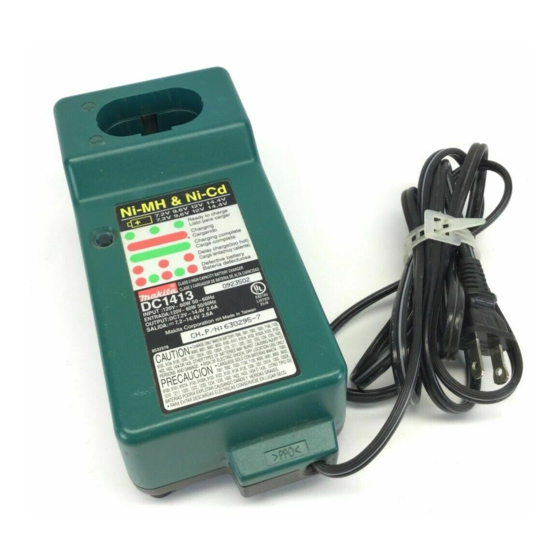
C
ONCEPTION AND MAIN APPLICATIONS
Both of Ni-Cd and Ni-MH batteries from 7.2V to 14.4V
can be charged with DC1413 (LG125), in shorter time
comparing with the existing charger DC1411.
Its maintenance (trickle) charging system keep the full charged
condition, even if the battery is left in this charger after
finish of charging process.
S
pecification
Voltage (V)
110
115
120
220
230
240
Output voltage : V
Output current : A
Charging time : minute
Protection of circuit from over current
DC1413
LG125 (for Dolmar brand)
Charger
Cycle (Hz)
Current (A)
50 / 60
50 / 60
50 / 60
50 / 60
50 / 60
50 / 60
Ni-Cd battery of 1.3Ah
Ni-Cd battery of 2.0Ah
Ni-MH battery of 2.6Ah
Ni-MH battery of 3.0Ah
W
Continuous Rating (W)
Input
60
60
60
60
60
60
7.2, 9.6, 12, 14.4
2.6
Approx. 30
Approx. 45
Approx. 60
Approx. 70
by Fuse
PRODUCT
L
Dimensions : mm ( " )
Length ( L )
193 (7-5/8)
Height ( H )
78 (3-1/16)
Width ( W )
92 (3-5/8)
Max. Output(W)
Output
P 1 / 4
H
Advertisement

Related Manuals for Makita DC1413


Summary of Contents for Makita DC1413
- Page 1 Charger ONCEPTION AND MAIN APPLICATIONS Both of Ni-Cd and Ni-MH batteries from 7.2V to 14.4V can be charged with DC1413 (LG125), in shorter time comparing with the existing charger DC1411. Its maintenance (trickle) charging system keep the full charged condition, even if the battery is left in this charger after finish of charging process.
- Page 2 P 2 / 4 eatures and benefits Ideal charging system in this class with the following installations * Controlling by micro computer : The installed micro computer perceives the full charged condition, and control the optimum way to stop the charging process, from the followings. A) Minus delta V system : Stop the charging process with perceiving the battery's voltage drop.
- Page 3 P 3 / 4 omparison of products MAKITA Model No. Specifications DC1413 DC1411 Chargeable battery voltage 7.2V - 14.4V 7.2V - 14.4V Approx. 30 min. Approx. 40 min. 1.3Ah Approx. 40 min. Approx. 50 min. 1.7Ah * Charging Approx. 45 min.
- Page 4 P 4 / 4 epair (2) Replacing damaged varistor a. Varistor is assembled on circuit board with solder. Remove it from circuit board with soldering iron. Circuit board Varistor Fig.2 When removing varistor, melt this part with soldering iron and remove varistor. b.