Table of Contents
Advertisement
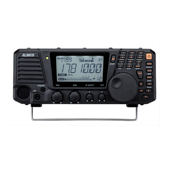
PS0633 DX-R8T/E
DX-R8T/E
COMMUNICATIONS RECEIVER
Instruction Manual
Thank you for purchasing your new ALINCO receiver.
This instruction manual (and addendum sheets) contains important safety and operating
instructions.
Please read this manual carefully before using the product and keep it for future reference.
Advertisement
Table of Contents

Related Manuals for Alinco DX-R8T


Summary of Contents for Alinco DX-R8T
- Page 1 DX-R8T/E COMMUNICATIONS RECEIVER Instruction Manual Thank you for purchasing your new ALINCO receiver. This instruction manual (and addendum sheets) contains important safety and operating instructions. Please read this manual carefully before using the product and keep it for future reference.
- Page 2 The FCC Part 15 approval is not required for use of this device in USA/Canada. Copyright © All rights reserved. No part of this document may be reproduced, translated or transcribed in any form or by any means without the prior permission of Alinco. Inc., Osaka, Japan, English Edition Printed in Japan.
- Page 3 PS0633 DX-R8T/E WARNING To prevent any hazard during operation of Alinco’s radio product, in this manual and on the product you may find symbols shown below. Please read and understand the meanings of these symbols before starting to use the product.
- Page 4 PS0633 DX-R8T/E WARNING The manufacturer declines any responsibilities against loss of life and property due to a failure of this product when used with or as a part of a device made by third parties. Use of third party accessory may result in damage to this product. It will void our warranty for repair.
- Page 5 PS0633 DX-R8T/E WARNING In case of emergency: In case of the following situation(s), please turn off the product, switch off the source of power, then remove or unplug the power-cord. Please contact your local dealer of this product for service and assistance. Do not use the product until the trouble is resolved. Do not try to troubleshoot the problem by yourself.
- Page 6 PS0633 DX-R8T/E WARNING About Receiver Do not connect devices other than specified ones to the jacks and ports on the product. It may result in damage to the devices. Turn off and remove the power-source (AC cable, DC cable, battery, cigar-cable, charger adapter etc) from the product when the product is not in use for extended period of time or in case of maintenance.
-
Page 7: Table Of Contents
PS0633 DX-R8T/E Contents Before Operating the Receiver.......... 7 Attention ....................7 Notice to California resident users ..........7 The receiver has no protection against lightning......7 Limited Power Source ...............7 Introduction................. 8 1. Getting Started ............... 9 1-1 Functions and Features ..............9 1-2 Standard Accessories ..............10... - Page 8 PS0633 DX-R8T/E Contents 5. Other Functions............40 5-1 Interference Reducers ..............40 IF SHIFT .................40 Narrow Filter ................41 CW BFO REVERSE ...............42 NB (Noise Blanker) ..............42 5-2 Other Useful Functions ..............43 RIT Function ................43 ± f (Plus-Minus Delta F) Function ..........43 VFO A=B Function ..............44...
-
Page 9: Before Operating The Receiver
Alinco will not take responsibility for any fire hazard associated with powering the receiver or charging its batteries using a power source that does not belong to the limited power source in... -
Page 10: Introduction
PS0633 DX-R8T/E Introduction Thank you very much for purchasing this excellent Alinco receiver. Our products are ranked among the finest in the world. This radio has been manufactured with state of the art technology and it has been tested carefully at our factory. It is designed to operate to your satisfaction for many years under normal use. -
Page 11: Getting Started
PS0633 DX-R8T/E 1. Getting Started 1-1 Functions and Features All mode receiver with IQ signal output Covers in SSB, AM, FM, CW and IQ signal output for SDR operation. General coverage Covers 150 kHz to 35 MHz in all modes. (T-version up to 30 MHz) ... -
Page 12: Standard Accessories
DX-R8T/E DC power cable (EDC-37) Includes 3A fuse Instruction manual (PS0629) DX-R8 Instruction manual Warranty certificate Warranty Policy: Please refer to any enclosed warranty information or contact your authorized Alinco dealer/distributor for the warranty policy before purchase. -
Page 13: Installation And Connection Basics
PS0633 DX-R8T/E 1. Getting Started 1-3 Installation and Connection Basics Connection Diagram 13.8 V regulated DC power supply Antenna Ground Headphones External speaker Procedure 1. Connecting an antenna and ground cable • Antenna connection Use a properly-adjusted (low SWR) antenna to obtain optimum performance from the receiver. A 50 ohm impedance coaxial with PL-259 connector is required for this connection. -
Page 14: Connecting Headphones
PS0633 DX-R8T/E 1. Getting Started 2. Connecting an external speaker (if not using the internal speaker) Connect a 3.5 mm diameter mono plug to the SPEAKER jack on the front panel. Use a 3 W or higher external speaker with 8 ohm impedance. - Page 15 PS0633 DX-R8T/E 1. Getting Started 5. Installing the control panel and body separately (optional) IMPORTANT: Be sure to disconnect the power cable before carrying out this procedure. Remove 2 screws above the main unit to s e p a r a t e t h e f r o n t - c o n t r o l p a n e l .
-
Page 16: Controls, Connectors, And Display
PS0633 DX-R8T/E 1. Getting Started 1-4 Controls, Connectors, and Display Front Panel (21) (22) (12) (11) (20) (10) (19) (18) (17) (16) (15) (14) (13) No. Key Principal Function (1) POWER SWITCH [ ] Turns the power on/o . -
Page 17: Keypad
PS0633 DX-R8T/E 1. Getting Started Keypad (23) (24) (25) (26) (27) (28) (29) (30) (31) (32) (33) (34) No. Name Function (23) Frequency direct input “1” (24) Frequency direct input “2” (25) Frequency direct input “3” (26) Frequency direct input “4”... -
Page 18: Rear Panel
PS0633 DX-R8T/E 1. Getting Started Rear Panel No. Name Function Antenna connector For connecting an antenna, takes a 50 ohm impedance coaxial cable with PL-259 connector. MUTE jack To mute the audio, make a simple switch circuit as shown (optional feature). -
Page 19: Display
PS0633 DX-R8T/E 1. Getting Started Display (10) (11) (13) (12) (14) (15) (16) No. Display Function Appears in the MEMORY mode, indicating the selected memory channel. Indicates the selected VFO mode A or B. AGC parameter, S for slow, F for fast. -
Page 20: Quick Reference For Control Keys
PS0633 DX-R8T/E 1. Getting Started Quick Reference for Control Keys There are 3 types of key operations; simply press it, press it after [FUNC] key, or press and hold it for more than 1 second (*). NOTE: FUNC + this key: Press [FUNC] key, then press this key. -
Page 21: Operation
PS0633 DX-R8T/E 2. Operation 2-1 Reception Basics 1. Turning the unit power on and off NOTE: Make sure that all antenna and power connections are correct before turning the power on. By pressing the [ ] key the power turns on. - Page 22 PS0633 DX-R8T/E 2. Operation 5. Setting the reception frequency Various method is available to select receiving frequency in DX-R8. Let's start with a conventional way by using [/] keys. • Each time the [M/KHz] key is pressed, shifts in the following manner: ...
-
Page 23: Direct Frequency Entry With Keypad
PS0633 DX-R8T/E 2. Operation Direct Frequency Entry with Keypad DX-R8 has a keypad for direct frequency entry as described below. Press the numeral keys on the keypad to enter the MHz digits for the desired frequency. If a key is mistakenly pressed, press any key except numeral keys and start again from the beginning. -
Page 24: Getting Familiar With Useful Functions
PS0633 DX-R8T/E 2. Operation Getting Familiar with Useful Functions In LW/MW/SW bands, receive conditions vary not only with bands and modes but with time and season. To obtain optimum signal reception, get familiar with and take full advantage of these versatile functions. - Page 25 PS0633 DX-R8T/E 2. Operation RIT (Receiver Incremental Tuning) Press the [RIT] key. The “RIT” icon will appear on the LCD. Rotate the RIT control knob to adjust the frequency. * To exit from the RIT function, press the [RIT] key repeatedly until both “RIT”...
-
Page 26: Rtty/Packet Operation (Fax/Sstv)
PS0633 DX-R8T/E 2. Operation 2-2 RTTY/Packet Operation (FAX/SSTV) DX-R8 has no dedicated features for RTTY packet, FAX, and SSTV receptions. However, these operations can be enabled by using the following procedures. Received data output The end of a 3.5 mm... -
Page 27: Iq Signal Output
PS0633 DX-R8T/E 2. Operation 2-3 IQ Signal Output The DX-R8 has an IQ signal output jack on the rear panel. If a commercially-available cable with a 3.5 mm diameter stereo mini plug on each end (this is the same cable as mentioned in the clone function section on page 48) is used to connect the IQ jack to a computer's Line-in jack, you will be able to use software that are available on the internet, such as SDR, FAX, RTTY, SSTV decoders and HFDL. -
Page 28: Memory Channels
MEMO: Some sample frequencies have been stored in factory. WWV=US Standard Frequency Station NHK=NHK Radio Japan World Program in English Aviation=HF aviation and VOLMET channels world-wide Alinco does not guarantee the accuracy of broadcasting/communications frequencies as they are subject to change occasionally. -
Page 29: Storing Data In Memory Channels
5. Read P.28 for memory operation. NOTE: To avoid overwriting, use overwrite protection in the Set mode menu 01, P.51. Use of the free utility software makes memory editing easy and convenient. Please visit alinco.com for details. -
Page 30: Memory Mode Operation
PS0633 DX-R8T/E 3. Memory Channels 3-3 Memory Mode Operation Procedure Accessing the Memory Mode P r e s s t h e [ V / M ] k e y t o d i s p l a y t h e channel number and MEMO. -
Page 31: Memory Channel Data Erasing
PS0633 DX-R8T/E 3. Memory Channels 3-4 Memory Channel Data Erasing Erasing Data in a Selected Memory Channel P r e s s t h e [ V / M ] k e y t o a c c e s s t h e Memory mode. -
Page 32: Memory To Vfo Data Transfer
PS0633 DX-R8T/E 3. Memory Channels 3-5 Memory to VFO Data Transfer Introduction This function copies data from any memory channel to the VFO. This is useful when you wish to tune in a station near the frequency stored in a memory channel. - Page 33 PS0633 DX-R8T/E 3. Memory Channels Enter the next character with the [ENT] key. (Repeat the same sequence) In order to store 6 letters for example, repeat the sequence until all 6 letters are entered by [ENT] key, and only 7th digit is flashing. To enter 7 letters, repeat until 1st digit flashes.
-
Page 34: Quick Memory
3-7 Quick Memory Frequencies for amateur bands are stored for the keypad keys as the default setting in the DX-R8T/E as listed below. After pressing the [ENT] key, if a keypad key is pressed, the corresponding stored frequency will appear. This function is useful for storing the mid-frequency of the broadcast bands you often listen to or the frequencies of the broadcast stations that you most frequently receive. -
Page 35: Scanning
With this scan mode, scanning is carried out with the steps set in VFO mode. If all the bands that can possibly be received were to be scanned, the scanning time would be too long so with the DX-R8T/E, amateur bands are categorized as separate, and scanning is conducted by scanning inside and outside of the amateur bands which makes it easier to nd the frequency band's wave. - Page 36 PS0633 DX-R8T/E 4. Scanning Programmed scan This function scans an user-speci ed range of frequencies. Before using this function, you need to specify the upper and lower frequency limits for programmed-scanning. These frequencies are called “Programmed scan channels”, and are available a pair in VFO A and VFO B separately.
-
Page 37: Scanning Conditions
PS0633 DX-R8T/E 4. Scanning Priority scan · In this scan mode, for each 5 seconds the displayed frequency is received, the set channel (priority frequency) will be received for 0.5 seconds. At this time, if a signal is received and the squelch is open, the set channel is received for 2 seconds. -
Page 38: Vfo Scan
PS0633 DX-R8T/E 4. Scanning 4-2 VFO Scan Enter to either the VFO A or B in the VFO mode. Press the [FUNC] key, then press the [4] key to start scanning. During this scan mode, the decimal points flash as shown. -
Page 39: Search Scan
PS0633 DX-R8T/E 4. Scanning 4-4 Search Scan By setting the Search scan in the Set mode Menu 04 and 100 kHz in the Menu 05: Enter to either the VFO A or B in the VFO mode. Set any frequency to scan in 100 kHz range and the modulation mode you desire. -
Page 40: Skip-Channel Setting
PS0633 DX-R8T/E 4. Scanning 4-6 Skip-channel Setting Memory channels that are set as skip-channels will be excluded from scanning during Memory Scan. This designation can be set even after the memory is programmed. Press the [FUNC] key in the Memory mode, and then press the [V/M] key while the FUNC icon is displayed. -
Page 41: Priority Scan
PS0633 DX-R8T/E 4. Scanning 4-7 Priority Scan You can monitor 2 frequencies every 5/0.5 seconds alternatively. Any combination of VFO and/or memory channel frequency can be coupled for priority monitoring. Stay tuned to the main frequency you wish to monitor for 5seconds, and select the priority frequency (or channel) to monitor 0.5 seconds (and stay there for 2 seconds if a... -
Page 42: Other Functions
PS0633 DX-R8T/E 5. Other Functions 5-1 Interference Reducers Introduction As explained in previous chapters, this receiver has built-in functions to reduce interferences. This section explains how to use these functions to reduce interference in detail, although you may be already familiar with these features. -
Page 43: Narrow Filter
PS0633 DX-R8T/E 5. Other Functions Narrow Filter The narrow lter can be used in AM, SSB and CW mode. This allows you to e ectively reduce interference. Pass band Pass band Standard lter Narrow lter · If there are interference signals (A) and (B) when the standard lter is used, using the narrow lter will reduce the interference. -
Page 44: Cw Bfo Reverse
PS0633 DX-R8T/E 5. Other Functions CW BFO REVERSE The CW mode has CWU (upper sideband) and CWL (lower fBFO sideband) options. Selecting the CWU or CWL can help reduce interference. When your receive frequency is zeroed-in with the other station's transmit frequency, this function would not a ect the receive tone. -
Page 45: Other Useful Functions
PS0633 DX-R8T/E 5. Other Functions 5-2 Other Useful Functions RIT Function Once tuned in the signal, instead of using the main dial, RIT may be used to ne-tune during the reception. RIT vary the frequencies within the range of ±1.2 kHz. -
Page 46: Vfo A=B Function
PS0633 DX-R8T/E 5. Other Functions VFO A=B Function This function copies the VFO setting A to B or vice versa. NOTE: This is useful when you wish to move to another similar operating condition by just slightly changing some settings, leaving the original status, or switch between these 2 conditions. -
Page 47: Multi Function Feature
PS0633 DX-R8T/E 5. Other Functions MULTI FUNCTION Feature Any key operation can be assigned to the [MF] key as a short-cut. * All key functions and Set mode parameters can be assigned to this feature. Example: Assign the scan speed setting in the Set mode to the [MF] key. -
Page 48: Dial Lock Function
PS0633 DX-R8T/E 5. Other Functions DIAL LOCK Function This function locks the main tuning dial to prevent accidental frequency changes. NOTE: While this function is activated, tuning is still possible with the [/] keys and RIT control knob. Procedure Press the [ ] key. -
Page 49: Beep Sound
PS0633 DX-R8T/E 5. Other Functions Beep Sound The beep that sounds during operation can be turned o . If the [FUNC] key is pressed, then the [0] key is pressed, the beep sound can be switched from being on to off and vice versa. When set to "OFF" the beep will not sound. -
Page 50: Cable Clone
PS0633 DX-R8T/E 5. Other Functions CABLE CLONE This feature will copy the programmed data and parameters in the master unit to slave units. It copies the parameters and memory program settings. Plug con guration (both for Master/Slave) 3.5 mm stereo-mini plug audio cable (option) -
Page 51: Parameter Setting Mode (Set Mode)
PS0633 DX-R8T/E 6. Parameter Setting Mode (Set mode) IMPORTANT: Please read the following pages thoroughly prior to the change of any parameters. THE PARAMETERS CANNOT BE SET WITHOUT ENTERING THE SET MODE. By entering the Parameter Setting mode, some of the radio’ s operating parameters can be changed to suit your preferences. -
Page 52: Menu 00. Setting Frequency Step With The [/] Keys
PS0633 DX-R8T/E 6. Parameter Setting Mode Setting Frequency Step with the [/] Keys Menu 00. SSB and CW Mode Menu number While the unit is in SSB or CW mode, enter into the Set mode and select menu The current frequency step will be displayed. -
Page 53: Iq Mode
PS0633 DX-R8T/E 6. Parameter Setting Mode IQ Mode While the unit is in IQ mode, enter into the Set mode and select menu 00. The current frequency step will be displayed. You can change the frequency step as below by rotating the main dial. -
Page 54: Menu 03. Timer Scan Setting
NAVTEX, or FAX data from multiple channels, if you input those channels into the memory and set the time to 3 or 5 minutes, the DX-R8T/E will automatically scan the input channels and receive data per the set time period. -
Page 55: Menu 04. Search Range Setting For Search Scan
PS0633 DX-R8T/E 6. Parameter Setting Mode Search Range Setting for Search Scan Menu 04. This is to set the scanning range applied to Search scanning. 50, 100 and 200 kHz are available as parameters. Default range is [SSC-50]. R o t a t e t h e m a i n d i a l t o s e l e c t t h e scanning range. -
Page 56: Menu 06. Automatic Usb/Lsb Selection
PS0633 DX-R8T/E 6. Parameter Setting Mode Automatic USB/LSB Selection Menu 06. This function automatically selects the USB or LSB mode depending on which amateur radio band has been selected in SSB mode. If “OFF” in selected, the last-used SSB mode is recalled regardless of the band. -
Page 57: Menu 08. Sleep Time Setting
PS0633 DX-R8T/E 6. Parameter Setting Mode Sleep Time Setting Menu 08. The sleep feature turns o the power after the desired time is elapsed regardless of operation status. The default setting is "SLP-60" (60 minutes). Use the main tuning dial to set the sleep time setting between 10 minutes and 180 minutes in increments of 10 minutes. -
Page 58: Menu 10. [/] Keys Repeat Setting
PS0633 DX-R8T/E 6. Parameter Setting Mode [/] Keys Repeat Setting Menu 10. Function for pressing [/] keys can be set to a key-repeat to increase/decrease values continuously (and faster) while holding down the key. T h e d e f a u l t i s [ K R P T - O N ] t h a t i s k e y - r e p e a t f u n c t i o n . -
Page 59: Menu 13. Cw Pitch Frequency Setting
PS0633 DX-R8T/E 6. Parameter Setting Mode CW Pitch Frequency Setting Menu 13. The sidetone will change according to the CW o set you select. The [CP-800] appears on the display. (Default) By rotating the main dial, the display changes as shown and the sidetone is changed. -
Page 60: Maintenance And Reference
PS0633 DX-R8T/E 7. Maintenance and Reference 7-1 Reset There are 3 types of reset modes in DX-R8. 1. System reset: Resets functions and Set mode parameters. Memory data remain unchanged. THIS IS THE MOST RECOMMENDED RESET OPERATION. 2. Memory reset: Resets memory channel data only. -
Page 61: Troubleshooting
PS0633 DX-R8T/E 7. Maintenance and Reference 7-3 Troubleshooting If a problem should occur, rst try the troubleshooting procedure given below. If the problem persists, contact your nearest ALINCO dealer for technical assistances. Symptom Possible Cause Remedy 1. Correctly connect cable. -
Page 62: Appendix
PS0633 DX-R8T/E Appendix Options · EDS-17 Front control separator kit (5 m cable) · EDC-37 DC power cable (spare) · EDC-36 cigar cable with noise lter · EF0010 3 A fuse for use with EDC-37 (spare) · ERW-7 PC connection cable... -
Page 63: After-Sales Customer Services
Repairs and other customer-service information: Please contact your dealer for details, or visit our website at alinco.com. About older products: We keep inventories of spare parts and minimum necessary accessories for at least 5 years since the product is discontinued. -
Page 64: Specifications
PS0633 DX-R8T/E Specifications General DX-R8 Reception frequency range (MHz) T : 150KHz to 29.99999MHz E : 150KHz to 34.99999MHz Memory channels 600 channels Receiving wave modes J3E(USB, LSB), A3E(AM), A1A (CW), F3E(FM) Antenna impedance 50 Ω Frequency stability ±1 ppm Power supply voltage 13.8 V DC ±15% (11.7 to 15.8 V) - Page 65 PS0633 DX-R8T/E ALINCO,INC. Head O ce: Yodoyabashi-Dai Building 13th Floor 4-9, 4-Chome, Koraibashi, Chuo-ku, Osaka 541-0043, Japan Phone: +81-6-7636-2362 Fax: +81-6-6208-3802 http://www.alinco.com/ E-mail: export@alinco.co.jp Printed in Japan Copyright Alinco. Inc. PS0633 FNEN-EN...