Table of Contents
Advertisement
Quick Links
User Manual
Hitachi
Printer
Model PB
Thank you for purchasing the Hitachi IJ Printer Model PB.
This printer employs a no contact, ink-jet method to print onto a print target. This instruction manual describes
the basic operating, maintenance, and other detailed handling procedures of the Hitachi IJ Printer Model PB.
If the printer is improperly handled or maintained, it may not operate smoothly and become defective or cause
an accident. It is therefore essential that you read this manual to gain a complete understanding of the printer and
use it correctly.
After thoroughly reading the manual, properly store it for future reference.
Advertisement
Table of Contents

Related Manuals for Hitachi PB Series


Summary of Contents for Hitachi PB Series
-
Page 1: User Manual
This printer employs a no contact, ink-jet method to print onto a print target. This instruction manual describes the basic operating, maintenance, and other detailed handling procedures of the Hitachi IJ Printer Model PB. If the printer is improperly handled or maintained, it may not operate smoothly and become defective or cause an accident. -
Page 2: Table Of Contents
Contents Safety Precautions Section 1. Overview Usage Precautions ................1–1 1.1.1 Notes on ink and makeup ink............1–1 1.1.2 IJ printer long-term shutdown............1–4 1.1.3 Print head cleaning ................1–5 1.1.4 Shutdown (no-cleaning stop) ............1–7 1.1.5 Operating hours ................1–8 Component Names and Functions............1–9 1.2.1 External views ...................1–9 1.2.2... - Page 3 Section 4. Setting the Operating Environment Operation Management................ 4–1 4.1.1 Overview ...................4–1 4.1.2 Operating procedure .................4–2 Setting the User Environment .............. 4–4 4.2.1 Overview ...................4–4 4.2.2 Operating procedure .................4–5 Setting the Date and Time..............4–7 4.3.1 Overview ...................4–7 4.3.2 Operating procedure .................4–7 Setting the Password ................
-
Page 4: Safety Precautions
Safety Precautions Before using the printer, thoroughly read the following safety precautions to ensure optimal utilization of the printer. You should observe the precautions set forth below in order to use the product properly and avoid endangering or causing damage to you or other persons. For the purpose of clarifying the severity of injury or damage and likelihood of occurrence, the precautions are classified in two categories, DANGER and CAUTION, which both describe the hazardous situations that may arise if you ignore the precautions and perform an incorrect handling or operating procedure. - Page 5 DANGER Ensure that there is no flame or arc generating device within a distance of 5 m to the printer. The ink and makeup ink are both flammable and may cause fire. Fire can be generated by matches, lighters, cigarettes, heaters, stoves, gas burners, welders, grinders, and static electricity.
- Page 6 Only use Hitachi-approved consumables and parts for periodic replacement. Using products not designated by Hitachi may lead to malfunction or failure. Such malfunction or failure will not be covered by the warranty. Warning for Mercury (Hg) -- THE LAMP IN THIS PRODUCT CONTAINS MERCURY.
- Page 7 DANGER When charging a refill of ink or makeup ink, exchanging ink, or otherwise handling ink or makeup ink, take appropriate care not to spill the ink or makeup ink. If you spill any ink or makeup ink accidentally, immediately wipe it off properly with wiping paper or similar.
- Page 8 CAUTION Only persons who have completed an operator training course for Hitachi IJP can operate and service the printer. If the printer is operated or serviced incorrectly, it may malfunction or break down. Do not attempt to make repairs for any purpose other than operation or maintenance.
- Page 9 CAUTION Ensure that all electrical wiring, connections and grounding comply with the applicable codes. Properly connect the printer to its dedicated ground. Complete the above procedure to avoid electric shock hazards. Ink and makeup ink must be stored as required for flammable liquids. Storage must comply with local regulatory requirements.
-
Page 11: Overview
1. Overview Usage Precautions 1.1.1 Notes on ink and makeup ink 1.1.1-1 Ink and makeup ink replenishment What is makeup ink? The printer employs an automatic ink/makeup ink replenishment system. While the The makeup ink printer is operating, the ink tank and the makeup ink tank, respectively, automatically serves as the replen- supply ink and makeup ink to the ink main tank at regular intervals. -
Page 12: Storage Precautions
1.1.1-3 Storage precautions 1. Store the ink and makeup ink in a cold and dark place (0 to 20 °C). (Observe this rule no matter whether the tanks are unsealed or not.) 2. The shelf life is predefined for the ink and makeup ink. Begin to use the ink/makeup ink before the "Expiration (opening) date"... - Page 13 2. Handling precautions a. When you use the JP-K31A, JP-K69, JP-K60, JP-F63, or JP-K68 ink, you must complete the print head air-purge procedure regardless of the humidity predominating in the environment in which the printer is operated. b. The JP-K31A and JP-K60 inks employ carbon black as the pigment. If an alarm for excess electrostatic charge is issued when no ink or makeup ink is on the print head surface and ink particles are properly generated, carbon black may be deposited on the print head surface.
-
Page 14: Ij Printer Long-Term Shutdown
1.1.2 IJ printer long-term shutdown In the case where the operation of the IJ printer is irregular (e. g. not used for a number of weeks, for instance) depending on production requirements or similar, problems may occur, such as no ink ejecting when operating the printer or no recovery possible due to accretion of the ink inside the printer. -
Page 15: Print Head Cleaning
1.1.3 Print head cleaning 1. Cleaning with the makeup ink should be restricted to the end of the print head. To clean the end of the print head with the makeup ink, orient the end of the print head downwards. When a print error or 2. - Page 16 4. When using JP-K31A ink, the following precautions must be observed. The charging and deflecting electrodes and a gutter are provided inside the print head. If highly conductive carbon black settles on the print head mounting base (made of insulating material), leakage can occur between these electrodes resulting in frequent recurrence of errors.
-
Page 17: Shutdown (No-Cleaning Stop)
1.1.4 Shutdown (no-cleaning stop) When you press the [Shut down] key in the upper right-hand corner of a screen, the printer stops after completing its automatic nozzle cleaning sequence. If you repeatedly activate the [Shut down] key to stop an operation, excessive makeup ink enters the printer, thereby diluting the ink or producing an unduly high solution level in the ink main tank. -
Page 18: Operating Hours
1.1.5 Operating hours If you frequently perform the shutdown procedure, excessive makeup ink enters the printer, thereby diluting the ink. For stable operation, be sure to run the printer as specified in the graphs. *1. Example. If you use JP-K69 ink at 20 °C, the IJ printer must eject the ink for one hour or more. *2. -
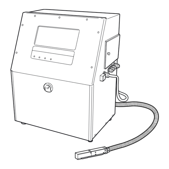
Page 19: Component Names And Functions
Component Names and Functions 1.2.1 External views Section 1 1.2 Component Names and Functions 1–9... -
Page 20: Main Body Internal Parts Arrangement
1.2.2 Main body internal parts arrangement 1–10 1.2 Component Names and Functions Section 1... -
Page 21: Print Head
1.2.3 Print head Section 1 1.2 Component Names and Functions 1–11... -
Page 22: Installation Precautions
Installation Precautions DANGER Ensure that there is no flame- or arc-generating device within a distance of 5 m to the printer. The ink and makeup ink are both flammable and may cause ignition or fire. Flames can be generated by matches, lighters, cigarettes, heaters, stoves, gas burners, welders, grinders, and static electricity. - Page 23 1 When positioning the end of the print head above the printer main body installation surface, ensure that the distance between the end of the print head and the installation surface does not exceed 1.5 m. 2 When positioning the end of the print head below the printer main body installation surface, ensure that the distance between the end of the print head and the installation surface does not exceed 1 m.
- Page 24 14. If you try to fix the print head using magnetic material (such as iron), the cover switch will not work correctly, resulting in a "Cover Open" error. Therefore, only use nonmagnetic resins or metals to fix the print head. 15.
-
Page 25: Basic Operating Procedures
2. Basic Operating Procedures Startup 2.1.1 Starting an operation CAUTION The ink and makeup ink employed contain organic solvents. When handling ink, wear protective gloves and safety goggles to avoid direct skin contact. The printer is provided with an LCD touch key panel. When manipulating the keys, do not apply excessive force to them. - Page 26 2. Hold wiping paper or similar against the ink ejection port at the end of the print head. Press the [Start up] and [Eject ink] keys in sequence. The ink jets out of the nozzle within the print head. Properly position wiping paper or similar to prevent the ejected ink from scattering.
- Page 27 If the ink jets out continuously, a fault exists. Section 1.1.4, "Shutdown (no- Press the [Manual] key to display the manual control menu. Press the cleaning stop)" [No cleaning stop] and [OK] keys in sequence to stop the ink ejection. Section 2.1.2, "If a fault occurs at the For the subsequent operations, see beginning of an operation".
-
Page 28: If A Fault Occurs At The Beginning Of An Operation
2.1.2 If a fault occurs at the beginning of an operation 1. Press the [Manual] key to display the control menu. Press the [No-cleaning stop] and [Shut down] keys in sequence to stop the ink ejection. 2. Remove the print head cover. This requires loosening its retaining screw. 2–4 2.1 Startup Section 2... - Page 29 3. Perform cleaning by pouring the intensifier over the area to be cleaned. Rinse the orifice plate, charge electrode, deflection electrodes, gutter, and Section 1.1.3, "Print mounting base with makeup ink to clean them. (Also refer to head cleaning".) * With wiping paper, thoroughly wipe the makeup ink away from the parts (mounting base included) surfaces, and then allow them to dry.
- Page 30 5. Make sure that the ink beam is positioned in the center of the gutter both horizontally and vertically as shown in the following figure. If the ink beam is not positioned in the center of the gutter, perform step 1 to stop the Section 6.6 in the Instruction ink ejection, and then proceed as described in Manual, "Correcting a Bent Ink Beam and Clogged Nozzle".
-
Page 31: Operations For Modifying The Setting Contents
2.1.3 Operations for Modifying the Setting Contents You can modify the setting contents (print description, character height, excitation voltage, etc.) in any of the states "Ready", "Standby" or "Stop". State in which settings can be changed State in which Classification Screen name settings can be changed... - Page 32 2. Switching between "Ready" state and "Standby" state (See Section 1.5.3-1 in the Instruction When the conveyor interlock is activated by the Ready output signal, be careful Manual "Ready not to switch to "Standby" state because this will stop the conveyor. Output Signal") You can abort the operation by pressing the [Manual] key from either the "Control menu"...
- Page 33 Precautions to be observed when changing the printings, print format, data When the following setup (1–2) is employed, the printing method is automatically switched to single-scan control. You should bear in mind that the print quality varies with the employed printing method, in particular when the Ink drop use percentage is 04.
-
Page 34: Shutdown
Shutdown Complete the ink stop process by performing the following steps. If you turn OFF the power without performing the ink stop process, the operation management information (operating time and print count) and count update will not be stored into memory. - Page 35 5. Install the print head cover. 6. Press the power ON/OFF switch to turn OFF the power. Using the nozzle rubber seal 1. To prevent the nozzle orifice plate from drying and accumulation of dust while the printer is transported or stored, a "nozzle rubber seal" was installed in the factory prior to shipment.
- Page 36 2–12 2.2 Shutdown Section 2...
-
Page 37: Editing Print Data And Printing
3. Editing Print Data and Printing Overview The content to be printed is entered in the "Print description" screen. Select the [Print format], [Edit message] or [Print spec.] screen from the menu and set the contents to be printed. The print image can be checked in the print layout area after you have made the entries. -
Page 38: Setting Print Format
Setting Print Format 3.1.1 Overview This procedure is used to set the line number, line spacing, character size, inter- character space, character width enlargement. The available 3.1.1-1 Line number functions, printable line count and The number of lines to be printed can be set. character sizes are different for every The settable number of lines is either one or two. - Page 39 3.1.1-4 Inter-character space The space between characters can be varied. The following settings are available: If a character size exceeds the range for this setting, the Character size Inter-character space nearest acceptable value will be used. 5 x 8 or 5 x 7 0 to 3 7 x 10 0 to 3...
-
Page 40: Operating Procedure
3.1.2 Operating procedure General instructions on the modification of Setting the line number to 2, line spacing to 1, character size to 7 x 10, inter- settings: Section 2.1.3, character space to 1, and increased character width to 2. "Operations for Modifying the Setting 1. -
Page 41: Printing Characters
Printing Characters Calendar characters, count characters, and special characters are available in addition Entry of calendar characters. to the normal characters. Section 3.2.2, 3.2.1 Printing fixed characters "Printing calendar characters". 3.2.1-1 Operating procedure Entry of count Enter "ABC" into the first line of the first row. The number of lines is set to 2. characters Section 3.2.6, "Printing count... - Page 42 5. Press [Apply]. 6. Press [Back]. The system returns to the "Print description" screen. 3–6 3.2 Printing Characters Section 3...
-
Page 43: Printing Calendar Characters
3.2.2 Printing calendar characters 3.2.2-1 Overview The following procedure is used to print the year, month, day, hours and minutes. The calendar time is the time indicated by Entries are made on the special keyboard. the internal clock of Calendar characters will be replaced by the current year, month, day, hours and the IJ printer. -
Page 44: Printing The Characters Indicating The Number Of Elapsed Days
5. Press [ • ], The "." mark appears. • • • • • • ] 6. Press [Month] twice. The display then shows [YY. MM • • • • • ], If you press [Month] only once, only the last digit of the month will be printed. 7. - Page 45 If the cursor is not displayed, 2. The "Edit message" screen opens. press [Show cursor]. 3. Press [Special]. The calendar-input keyboard appears. 4. Press [Total days]. Pressing [Total days] once prints the lowest digit of the number of elapsed days (T appears in the display).
-
Page 46: Printing Week Number
3.2.4 Printing week number 3.2.4-1 Overview Use this function when you want to print which week of the year the current week is. Use the calendar/count keyboard to input data. This function is interlocked with the calendar time that takes offset into consideration. - Page 47 3. Press [Special]. The calendar-input keyboard appears. 4. Press [Week number] twice. 5. Press [Apply]. 6. Press [Back]. You are returned to the "Print description" screen. The print image area reads "27". Section 3 3.2 Printing Characters 3–11...
-
Page 48: Printing Day Of The Week
3.2.5 Printing day of the week 3.2.5-1 Overview Use this function when expressing the day of the week as an one-digit character and printing it. Use the calendar/count keyboard to input data. This function is interlocked with the calendar time that takes offset into consideration. - Page 49 4. Press [Day of the Week]. 5. Press [Apply]. 6. Press [Back]. You are returned to the "Print description" screen. The print image area reads "4". Section 3 3.2 Printing Characters 3–13...
-
Page 50: Printing Count Characters
3.2.6 Printing count characters 3.2.6-1 Overview The numerical value of a predefined item is incremented or decremented every time it is printed. Count character entries are made on the special keyboard. 3.2.6-2 Operating examples General instructions on the modification of 1 Procedure for printing the numbers from 000001 to 199999 in the second line by settings: incrementing the printed number by one after every printing. - Page 51 5. Press [Count conditions]. If the cursor is not displayed, The "Count conditions" screen opens. press [Show cursor]. 6. Change the following settings. Value [000001 Range [000000 [199999 Direction Update [000000] Jump [199999 ] [000001] [000001 ] Entry procedures Function Increment Increments a numeric setting.
- Page 52 2 Procedure for printing the numbers from 000001-001000 through 010001 to 991000 in the second line, by incrementing the printed number by one after every printing. 1. Perform the steps 1 through 5 of procedure 1. 2. Change the following settings. The cursor moves to the second line.
-
Page 53: Setting Character Height And Character Orientation
Setting Character Height and Character Orientation 3.3.1 Overview The procedure for setting the character height, character width, character orientation and write position is described below. "Product speed 3.3.1-1 Character height matching" Section 4.2, The character height can be specified. "Setting the User Environment"... -
Page 54: Printing Method
3.3.1-3 Character orientation The character orientation and printing direction can be specified. The following settings are available. Setting Feed direction ABC The results of printing "ABC123" are as shown below: Setting Printing results A B C 1 2 3 ABC ... - Page 55 You should set the write position on individual character basis and then perform the fine adjustments on individual scan basis. The position relationship between the sensor and nozzle is as indicated below: When the nozzle is positioned before the sensor When the nozzle is positioned before the sensor Sensor Sensor...
-
Page 56: Operating Procedure
3.3.2 Operating procedure Set the character height to 90, character width to 10, character orientation to 1. For general instructions on the 1. From the "Print description" screen, press [Print spec.]. modification of settings, see The "Print specifications" screen opens. (The maximum value for the write position Section 2.1.3, varies with the character size.) "Operations for... -
Page 57: Setting Repeat Print
Setting Repeat Print 3.4.1 Overview This function is used to print the same print description continuously. Configure the "Repeat intervals" and "Repeat count" settings for repeat print. 1 Repeat print intervals: The size of the print target can be specified. This setting is performed when print targets are transported in close contact to each other (i.e. -
Page 58: Operating Procedure
3.4.2 Operating procedure Setting the repeat intervals and repeat count. 1. Press [Print spec.] on the Printing description screen. The "Print specifications" display will appear. 2. Press [Next display]. The second page of "Print specifications" screen will appear. 3. Set the repeat intervals. The unit of repeat intervals can be changed by pressing [Character unit CH] or [Scanning unit SC]. -
Page 59: Printing Future Date And Time
Printing Future Date and Time 3.5.1 Overview Date/time setup can be performed by adding offset values to the date/time of Offset values: Values to be added to the the internal clock. current date and time The following offset values can be used: values Year 0~99... -
Page 60: Operating Procedure
Example for yearly offset Calendar clock Day preceding same day Same day date 1 year 4 years 1 year 4 years 29.02.08 28.02.09 28.02.12 28.02.09 29.02.12 For selection between "Day preceding same day" and "Same day", see Section 4.2, "Setting the User Environment". 3.5.2 Operating procedure Setting the "USE BY"... - Page 61 4. Touch the line to set Month. The cursor moves to the "Month" field. 5. Press [0], [0], [0], and [1] successively. 6. Press [Apply]. To continue with the offset setting for another item, touch the line of the item to be set and repeat the steps 4 and 5.
-
Page 62: Saving Edited Print Data
Saving Edited Print Data 3.6.1 Overview You can save edited print data. Registration numbers are automatically assigned to print data. The message names must be uniquely defined. 3.6.2 Operating procedure Saving print data using the message name "ABC". 1. From the "Print description" screen, press [Save message]. For general instructions on the modification of... -
Page 63: Recalling Saved Data
Recalling Saved Data 3.7.1 Overview You can recall saved print data. 3.7.2 Operating procedure Recalling the print data named "FFFFFFFFFFFF" 1. From the "Print description" screen, press [Select message]. For general instructions on the modification of settings, see Section 2.1.3, "Operations for Modifying the Setting Contents". - Page 64 3–28 3.7 Recalling Saved Data Section 3...
-
Page 65: Setting The Operating Environment
4. Setting the Operating Environment Operation Management 4.1.1 Overview You can predefine the operating conditions. The operating time and print count are stored in memory every hour (at 00 minute). If power failure occur, the previously stored status will be restored. Item Description •... -
Page 66: Operating Procedure
4.1.2 Operating procedure 4.1.2-1 Setting the operating time to 0 and print count to 0 1. Select [Maintenance] from the menu. For general instructions on the modification of settings, see Section 2.1.3, "Operations for Modifying the Setting Contents" The "Maintenance menu" screen opens. 2. - Page 67 5. Press [Reset]. The print count field then indicates a print count of [000000000]. 6. Press [Apply]. 7. Press [OK]. The system returns to the "Maintenance menu" screen. Entry procedures Function Resets the value to 0 when the cursor is placed in the Reset operating time, alarm time, print count, or cumulative operating time field.
-
Page 68: Setting The User Environment
Setting the User Environment 4.2.1 Overview Setup item Description Default • When printing is conducted with this feature Product speed activated, the character width is maintained Not provided matching irrespective of the transport speed of the print target. • Specifies the frequency division that determines the intervals at which the encoder signal is recognized. -
Page 69: Operating Procedure
4.2.2 Operating procedure Setting the product speed matching feature to "Enable", frequency division to "1/3". For general instructions on the 1. Choose [Maintenance] from the menu. modification of The "Maintenance menu" screen appears. settings, see Section 2.1.3, "Operations for Modifying the Setting Contents". - Page 70 5. Press [1]. The product speed matching field then shows "1: Enable" so that frequency division input is acceptable. 6. Touch the line to set Frequency division. The cursor moves to the frequency division input field. 7. Press [0], [0], and [3] successively. The frequency division input field then shows "3".
-
Page 71: Setting The Date And Time
Setting the Date and Time 4.3.1 Overview The time values to be printed can be set in accordance with the calendar time. When the password is set up, the current Either of the following two setup methods can be used. time cannot be changed. - Page 72 4. Press [2]. The calendar time control field then shows "clock stop" to allow entry of the calendar time. 5. Touch the line to set Calendar time control. Press [ ] eight times. The cursor moves to the "hour" input field. 6.
-
Page 73: Setting The Password
Setting the Password 4.4.1 Overview You can set a password to restrict the access to certain functions. A password can have 1 to 12 characters. Acceptable characters for a password are the characters 0–9 and A–Z. Entry of the current password is required to change the password. Letters used in the password are case-insensitive. - Page 74 5. Press [C], [Z], [B], [0], and [5] successively. 6. Touch the line to set New password field. The cursor is placed in the new password reentry field. 7. Press [C], [Z], [B], [0], and [5] successively. 8. Press [OK]. The password is updated, and you are returned to the "Environment setup menu"...
-
Page 75: Controlling The Executable Functions
Controlling the Executable Functions 4.5.1 Overview You can disable the "print data change", "select/save message", and "print specifications" functions. When these functions are disabled, the keys assigned to them will not be Password setup. displayed. Section 4.4, "Setting the No functional limitations can be imposed unless the password is entered correctly. Password"... -
Page 76: Operating Procedure
4.5.2 Operating procedure Restricting the access to the print data change function The following description assumes 1. Choose [Maintenance] from the menu. that the password is "CZB05". For general instructions on the The "Maintenance menu" screen opens. modification of settings, see Section 2.1.3, "Operations for Modifying the Setting... - Page 77 5. Press [Enter Password]. The cursor moves to the print data change field, allowing you to make entries for changing print data, recall/registration, and print specifications. 6. Press [1]. The access to the print data change function is then restricted. 7.
- Page 78 4–14 4.5 Controlling the Executable Functions Section 4...
-
Page 79: Auxiliary Function
5. Auxiliary Function You can reduce created print data and create or update user patterns. The associated functions are selected from the auxiliary function menu screen. Sorting Created Print Data 5.1.1 Changing the message number 5.1.1-1 Overview Two sets of print data can be interchanged by exchanging the registration numbers. - Page 80 4. Press [Select/deselect]. The line No. 3 is then shaded with the cursor positioned over line No. 4. 5. Touch the line No.7. The cursor moves to line No. 7. 6. Press [Select/deselect]. The on-screen indication changes Line No. 7 is then shaded with no cursor displayed. from "blue"...
-
Page 81: Deleting Registered Data
5.1.2 Deleting registered data 5.1.2-1 Overview You can delete saved print data. 5.1.2-2 Operating procedure Deleting the data registered in position No. 2 For general 1. Verify that the printer is in "Stop" or "Standby" state. instructions on the modification of Choose [Auxiliary function] from the menu. - Page 82 4. Press [Select]. The deletion confirmation message appears. If more than 13 sets of print data are registered, press [Next list] or [Previous list] to see the rest of the list. 5. Press [Execute deletion]. The "BBBBBBBBBBBB" print data is then deleted. 6.
-
Page 83: Changing A Message Name
5.1.3 Changing a message name 5.1.3-1 Overview You can change the message name of saved print data. 5.1.3-2 Operating procedure Changing the message name of saved data from "AAAAAAAAAAAA" to "ABC9701". For general 1. Verify that the printer is in "Stop" or "Standby" state. Choose [Auxiliary function] instructions on the from the menu. - Page 84 4. Press [A], [B], [C], [9], [7], [0], and [1] successively. The new message name field then shows "ABC9701AAAAA". 5. Press [Delete] five times. 6. Press [OK]. The data selection screen for a change of the message name opens. If the message name you entered already exists, the "Duplicated message name" message appears.
-
Page 85: Creating A User Pattern
Creating a User Pattern 5.2.1 Saving a user pattern 5.2.1-1 Overview You can create and save user pattern designs. Up to 40 characters can be saved (in every character size). Three different character sizes can be generated: 5 x 8, 7 x 10, 12 x 16 An inter-character space between 0 and 8 can be selected. - Page 86 The cursor is positioned at the upper left corner of the pattern creation area. To move the cursor, use the key matrix located beside the dot pattern creation area. Examples for moving the cursor are shown below. 5–8 5.2 Creating a User Pattern Section 5...
- Page 87 Two different cursors are available: Move mode Displayed: The cursor is moved to a dot setup position. Reversal mode Displayed: The dots at the positions the cursor is moved to are reversed. To change the cursor type, press [Invert next]. 3.
- Page 88 6. Press [ ] four times successively. This moves the cursor to toward the upper and reverse. 7. Press [ ] four times successively. The cursor moves toward the lower left-hand corner and reverses. 8. Press [Save]. The "Pattern save" screen opens. 9.
-
Page 89: Recalling A User Pattern
5.2.2 Recalling a user pattern 5.2.2-1 Overview A registered user pattern can be recalled and displayed in the "User pattern creation" screen. 5.2.2-2 Operating procedure Recalling a pattern with a character size of 5 x 7, registered at the No. 3 position 1. - Page 90 4. Select the pattern displayed at the third position from the left. The third pattern is then displayed in reverse presentation (white on black). To see another page, press [Next char. set]. 6. Press [OK]. The system then returns you to the "User pattern creation" screen and displays the selected pattern in the editing area.
-
Page 91: If A Warning Condition/Fault Occurs
6. If a Warning Condition/Fault Occurs Indications Given When a Warning Condition/Fault Occurs When an warning condition or fault occurs, the warning or fault lamp comes on. A confirmation message appears to indicate an operating error or to prompt for process judgment. - Page 92 2. When a warning condition occurs When you press [Erase message], the warning window clears but the warning condition persists. The warning display area (see figure above) indicates the name of the warning condition. When the warning condition is cleared, the warning indication automatically disappears.
-
Page 93: On-Screen Message Descriptions
60 minutes after indication of the warning) The automatic Contact your nearest Replenishment Time-out replenishment sequence Hitachi distributor. is taking too much time. Clean the gutter, deflection electrode, and adjacent parts. The ink particles are Adjust the excitation... - Page 94 The high-voltage power Contact your nearest 11 Deflection Voltage Fault supply output voltage is Hitachi distributor. too low or too high. DC Power Supply Fan Failure of the power Contact your nearest Fault supply section.
- Page 95 6.2.1-2 Faults not causing ink stoppage Message Meaning of message Remedy If the printing fre- quency is high, The next print start signal decrease it. was input before the Print Overlap Error current printing operation If the print start signal was completed.
- Page 96 Message Meaning of message Remedy Clean the gutter, deflection electrode, adjacent parts. Adjust the excitation setting to make sure The value of the signal that the ink particles 10 Ink Drop Charge Too High that detects the particle are properly shaped. charge is too high.
-
Page 97: Warning Messages
Failure of the ink heating Contact your nearest Ink Heating Failure section. Hitachi distributor. Contact your nearest Hitachi distributor. When you start print- ing, set the correct cal- The voltage of the built-in endar time again from Battery Low battery is too low. - Page 98 Message Meaning of message Remedy Determine the opti- mum excitation setup Excitation setting needs to value running the noz- 13 Excitation Setting Review be reviewed. zle property test, and update the old excita- tion setup value. 6–8 6.2 On-screen Message Descriptions Section 6...
-
Page 99: Viewing The Warning Condition And Fault Occurrences
Viewing the Warning Condition and Fault Occurrences 6.3.1 Overview You can view the time of occurrence and description of warning conditions/fault messages. Up to 70 warning conditions/fault messages are memorized by the system. When the number of messages exceeds 70, the oldest message is erased. 6.3.2 Operating procedure 1. - Page 100 6–10 6.3 Viewing the Warning Condition and Fault Occurrences Section 6...
-
Page 101: Emergency Procedures
7. Emergency Procedures Press the power ON/OFF switch to turn OFF the power. DANGER If an earthquake, fire, or other emergency arises while the printer is print- ing or energized, turn OFF the power by pressing the power ON/OFF switch. Never perform this procedure except in case of emergency. Immediately after the emergency is cleared, press the power ON/OFF switch to turn the power back ON and press the [Start up] key to initiate ink ejection. - Page 102 7–2 Emergency Procedures Section 7...
-
Page 103: Maintenance
Maintenance To maintain the IJ printer in an optimum operating condition, you should perform the following maintenance programs. If you use the JP-K31A ink, other maintenance programs than those described Section 1.1.1-4, "Ink differences and handling below are required. See precautions"... -
Page 104: Other Maintenance Programs
Parts to be replaced periodically The clock battery, circulation system parts (pump, solenoid valve, etc.), and heating unit need periodic replacement. Consult your Hitachi distributor. 8.3.1 Air filter replacement procedure 1. Loosen the knob and remove the air filter cover. - Page 105 2. Remove the air filter and place a new filter, making sure the orientation is correct. (1) First insert the top of air filter. (2) Place the bottom of air filter on the guide. 3. Reattach the air filter cover. (1) First hook the square slot at the (2) Turn the knob until the air filter cover bottom of air filter cover onto the...
-
Page 106: Ink And Makeup Ink Part Code Numbers
8.3.3 Description of maintenance services Your Hitachi ink jet printer is warranted against defective material or workmanship for a period of one year or 2400 operating hours from the date of purchase (free of charge). In the event of any of the failures listed below, repairs will be charged even within the warranty period. -
Page 107: Parts Availability
6. Failures caused by fire, flood, or other disaster. Hitachi will not be liable for any manufacturing loss due to downtime of the ink jet printer and product damages (product or facility loss) caused by failure or malfunction of the ink-jet printer. However, in the event of a printer failure, Hitachi will send service engineers as soon as possible to repair the printer and reduce the downtime. - Page 108 8–6 8.3 Parts to be replaced periodically Section 8...