National Instruments SCB-68 User Manual
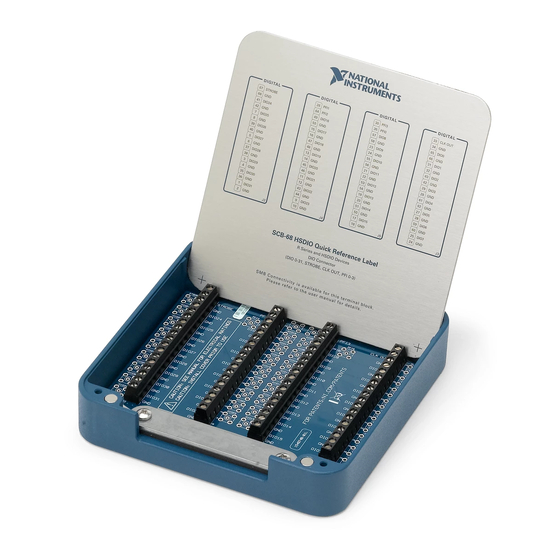
68-pin shielded connector block
Hide thumbs
Also See for SCB-68:
- User manual (64 pages) ,
- User manual (8 pages) ,
- Getting started (10 pages)

Related Manuals for National Instruments SCB-68


Summary of Contents for National Instruments SCB-68
- Page 1 SCB-68 68-Pin Shielded Connector Block User Manual SCB-68 Shielded Connector Block User Manual December 2002 Edition Part Number 320745B-01...
- Page 2 Switzerland 056 200 51 51, Taiwan 02 2528 7227, United Kingdom 01635 523545 For further support information, refer to the Technical Support and Professional Services appendix. To comment on the documentation, send email to techpubs@ni.com. © 1994–2002 National Instruments Corporation. All rights reserved.
-
Page 3: Important Information
Warranty The SCB-68 is warranted against defects in materials and workmanship for a period of one year from the date of shipment, as evidenced by receipts or other documentation. National Instruments will, at its option, repair or replace equipment that proves to be defective during the warranty period. - Page 4 Classification requirements are the same for the Federal Communications Commission (FCC) and the Canadian Department of Communications (DOC). Changes or modifications not expressly approved by National Instruments could void the user’s authority to operate the equipment under the FCC Rules.
- Page 5 Canadian Department of Communications This Class B digital apparatus meets all requirements of the Canadian Interference-Causing Equipment Regulations. Cet appareil numérique de la classe B respecte toutes les exigences du Règlement sur le matériel brouilleur du Canada. Compliance to EU Directives Readers in the European Union (EU) must refer to the Manufacturer’s Declaration of Conformity (DoC) for information* pertaining to the CE Marking compliance scheme.
-
Page 6: Table Of Contents
Differential Inputs ...3-4 Single-Ended Inputs...3-4 Differential Connection Considerations (DIFF Input Mode)...3-5 Differential Connections for Ground-Referenced Signal Sources...3-6 Differential Connections for Nonreferenced or Floating Signal Sources ...3-7 © National Instruments Corporation Using Bias Resistors ...3-7 SCB-68 Shielded Connector Block User Manual... - Page 7 Special Consideration for Analog Input Channels... 5-14 Special Consideration for Analog Output Signals ... 5-14 Special Consideration for Digital Trigger Input Signals ... 5-15 Measuring a 4 to 20 mA Current... 5-16 Theory of Operation... 5-16 SCB-68 Shielded Connector Block User Manual viii ni.com...
- Page 8 Quick Reference Labels Appendix C Fuse and Power Appendix D SCB-68 Circuit Diagrams Appendix E Soldering and Desoldering on the SCB-68 Appendix F Technical Support and Professional Services Glossary Index © National Instruments Corporation SCB-68 Shielded Connector Block User Manual...
-
Page 9: About This Manual
About This Manual This manual describes the SCB-68 and explains how to use the connector block with National Instruments data acquisition (DAQ) devices. Conventions The following conventions appear in this manual: <> Angle brackets that contain numbers separated by an ellipsis represent a range of values associated with a bit or signal name—for example,... -
Page 10: Ni Documentation
About This Manual NI Documentation For more information about using the SCB-68 with DAQ devices, refer to the following resources: • • SCB-68 Shielded Connector Block User Manual DAQ device user manuals, at ni.com/manuals NI Developer Zone, at ni.com/zone ni.com... -
Page 11: Introduction
Introduction The SCB-68 is a shielded I/O connector block with 68 screw terminals for easy signal connection to a National Instruments 68- or 100-pin DAQ device. The SCB-68 features a general breadboard area for custom circuitry and sockets for interchanging electrical components. These sockets or component pads allow RC filtering, 4 to 20 mA current sensing, open thermocouple detection, and voltage attenuation. -
Page 12: Quick Reference Label
These labels show the switch configurations and define the screw terminal pinouts for compatible DAQ devices. You can put the label on the inside of the SCB-68 cover for easy reference if you are using one of these devices. Refer to Appendix B, configurations and screw terminal pinouts that are included on each quick reference label. - Page 13 R6868 PSHR68-68-D1, PR6868F SH68-68-D1 R6868 Real-Time (RT) Devices SH68-68-EP SH68-68R1-EP, R6868 SH68-68-D1 R6868 SCB-68 Shielded Connector Block User Manual Chapter 1 Introduction Features Direct feedthrough only Thermocouple measurements Open thermocouple detection Current input Filtering Voltage dividers AC coupling Direct feedthrough only...
- Page 14 NI 4350 for USB NI 4351 for PCI/PXI/CompactPCI NI 445X for PCI NI 455X for PCI NI 5411 for PCI/PXI/CompactPCI NI 5431 for PCI/PXI/CompactPCI SCB-68 Shielded Connector Block User Manual Cable Assembly S Series Devices SH68-68-EP SH68-68R1-EP, R6868 SH68-68-EP SH68-68R1-EP, R6868...
-
Page 15: Installing Cables
Using 68-Pin Cables Table 1-1 lists the 68-pin cable assemblies that can connect the SCB-68 to a 68-pin DAQ device. Each end of these 68-pin cables has a 68-pin I/O connector that you can connect to the SCB-68 and to the 68-pin DAQ device. -
Page 16: Using 100-Pin Cables
Chapter 1 Introduction Figure 1-2 shows how to use a 68-pin cable to connect the SCB-68 to a 68-pin DAQ device. 1 68-Pin Cable Assembly 2 68-Pin DAQ Device 3 68-Pin I/O Connector Using 100-Pin Cables You can use the SH1006868 cable assembly to connect two SCB-68 connector blocks to a 100-pin DAQ device. - Page 17 3 SH1006868 Cable Assembly Figure 1-3. Connecting a 100-Pin DAQ Device to Two SCB-68 Connector Blocks When you attach two SCB-68 devices to the SH1006868 cable, one of the SCB-68 connector blocks has a full 68-pin I/O connector pinout, and the other SCB-68 connector block has an extended AI or extended digital pinout.
- Page 18 13 47 DIO3 DGND 12 46 SCANCLK PFI0/TRIG1 11 45 EXTSTROBE* PFI1/TRIG2 10 44 DGND DGND PFI2/CONVERT* PFI3/GPCTR1_SOURCE DGND PFI4/GPCTR1_GATE PFI5/UPDATE* GPCTR1_OUT PFI6/WFTRIG DGND DGND PFI7/STARTSCAN PFI8/GPCTR0_SOURCE GPCTR0_OUT DGND FREQ_OUT DGND Figure 1-4. SCB-68 E Series I/O Connector Pinout (Full) ni.com...
- Page 19 ACH52 13 47 ACH61 12 46 ACH54 11 45 ACH55 10 44 NC = No Connect Figure 1-5. SCB-68 E Series I/O Connector Pinout (Extended AI) SCB-68 Shielded Connector Block User Manual Chapter 1 Introduction ACH16 ACH25 ACH26 ACH19 ACH28...
- Page 20 21 55 20 54 19 53 18 52 17 51 16 50 15 49 14 48 13 47 12 46 11 45 10 44 NC = No Connect Figure 1-6. SCB-68 E Series I/O Connector Pinout (Extended Digital) 1-10 ni.com...
-
Page 21: Configuring The Scb-68
Do not operate the SCB-68 in a manner not specified in this document. Misuse of the SCB-68 can result in a hazard. You can compromise the safety protection built into the SCB-68 if the device is damaged in any way. If the SCB-68 is damaged, return it to NI for repair. - Page 22 You must insulate signal connections for the maximum voltage for which the SCB-68 is rated. Do not exceed the maximum ratings for the SCB-68. Remove power from signal lines before connecting them to or disconnecting them from the SCB-68.
- Page 23 Installation Category IV is for measurements performed at the source of the low-voltage (<1,000 V) installation. Examples of Installation Category IV are electric meters, and measurements on primary overcurrent protection devices and ripple-control units. 1-13 Chapter 1 Introduction SCB-68 Shielded Connector Block User Manual...
-
Page 24: Parts Locator And Wiring Guide
Keep away from live circuits. Do not remove equipment covers or shields unless you are trained to do so. If signal wires are connected to the SCB-68, dangerous voltages may exist even when the equipment is powered off. To avoid dangerous electrical shock, do not perform procedures involving cover or shield removal unless you are qualified to do so. -
Page 25: Screw Terminals
2 Switches S3, S4, and S5 3 68-Pin I/O Connector 4 Fuse (0.8 A) 5 Switches S1 and S2 6 Assembly Number and Revision Letter 7 Screw Terminals SCB-68 Shielded Connector Block User Manual S4 S3 R4(F) RC4(E) R5(G) R6(F) -
Page 26: Switch Configuration
You can now connect the SCB-68 to the 68-pin I/O connector. Switch Configuration The SCB-68 has five switches that must be properly configured to use the SCB-68 with the DAQ device. Table 2-1 illustrates the available switch configurations and the affected signals for each switch setting. Refer to... - Page 27 Temperature Sensor S5 S4 S3 Temperature sensor disabled, and accessory power enabled Note: This configuration is the factory-default configuration. SCB-68 Shielded Connector Block User Manual Signal Conditioning Circuitry Power (Off) Signal Conditioning Circuitry Power (On) Applicable Signals...
- Page 28 © National Instruments Corporation Signal Conditioning Circuitry Power (On) Signal Conditioning Circuitry Power (On) ni.com/manuals Chapter 2 Parts Locator and Wiring Guide Applicable Signals Single-ended analog input Differential analog input ni.com/manuals to determine if the device supports SCB-68 Shielded Connector Block User Manual...
-
Page 29: Connecting Signals
Connecting Signals This chapter describes the types of signal sources that you use when configuring the channels and making signal connections to the SCB-68, describes input modes, and discusses noise considerations to help you acquire accurate signals. Connecting Analog Input Signals The following sections describe how to connect signal sources for single-ended or differential (DIFF) input mode. - Page 30 Voltage – Single-Ended — Nonreferenced Common- (NRSE) Mode Voltage Refer to the Using Bias Resistors section for information on bias resistors. SCB-68 Shielded Connector Block User Manual Signal Source Type Floating Signal Source ACH(+) ACH(–) – AIGND – AIGND –...
-
Page 31: Nonreferenced Or Floating Signal Sources
10 to 100 kΩ resistor connected to AIGND on one input if they are DC coupled or on both inputs if sources are AC coupled. You can install bias resistors in positions B and D of the SCB-68, as shown in Figure 5-1, Analog Input Channel Configuration Diagram for ACH<i> and ACH<i+8>. -
Page 32: Ground-Referenced Signal Sources
Some versions of the SCB-68 use hardwired 0 Ω resistors as the factory-default Note jumpers. In such cases, to move these jumpers to and from the factory-default positions, you must solder and desolder on the SCB-68 circuit card assembly. When soldering, refer to Appendix E, Soldering and Desoldering on the... -
Page 33: Differential Connection Considerations (Diff Input Mode)
Some versions of the SCB-68 use hardwired 0 Ω resistors as the factory-default Note jumpers. In such cases, to move these jumpers to and from the factory-default positions, you must solder and desolder on the SCB-68 circuit card assembly. When soldering, refer to Appendix E, Soldering and Desoldering on the... -
Page 34: Differential Connections For Ground-Referenced Signal Sources
DAQ device ground, shown as V Figure 3-2. SCB-68 Shielded Connector Block User Manual ACH+ or ACH< i > ACH– or ACH< i +8>... -
Page 35: Differential Connections For Nonreferenced Or Floating Signal Sources
AIGND Measurement Device Configured in DIFF Input Mode *AISENSE is not present on all devices. Figure 3-3. Differential Input Connections for Nonreferenced Signals Chapter 3 Connecting Signals Instrumentation Amplifier PGIA Measured – Voltage – SCB-68 Shielded Connector Block User Manual... -
Page 36: Single-Ended Connection Considerations
Electrical coupling is a function of how much the electric field differs between the two conductors. SCB-68 Shielded Connector Block User Manual The input signal is high-level (greater than 1 V). The leads connecting the signal to the DAQ device are less than 10 ft (3 m). -
Page 37: Single-Ended Connections For Floating Signal Sources (Rse Input Mode)
© National Instruments Corporation AISENSE* AIGND Measurement Device Configured in RSE Input Mode *Not all devices support RSE input mode. Chapter 3 Connecting Signals Instrumentation Amplifier PGIA Measured – Voltage – SCB-68 Shielded Connector Block User Manual... -
Page 38: Connecting Analog Output Signals
I/O Connector Connecting Analog Output Signals When using the SCB-68 with a 68-pin or 100-pin DAQ device, the AO signals are DAC0OUT, DAC1OUT, EXTREF, and AOGND. DAC0OUT is the voltage output channel for AO channel 0. DAC1OUT is the voltage output channel for AO channel 1. -
Page 39: Connecting Digital Signals
SCB-68 and the DAQ device. Connecting Digital Signals When using the SCB-68 with a 68-pin or 100-pin DAQ device, the DIO signals are DIO<0..7> and DGND. DIO<0..7> are the eight single-ended DIO lines, and DGND is the ground reference. You can program all lines individually to be inputs or outputs. -
Page 40: Connecting Timing Signals
The remaining timing signals use five different dedicated outputs. Note For more information, refer to the device user manual at detailed signal description and connection information. SCB-68 Shielded Connector Block User Manual +5 V TTL Signal Switch I/O Connector Figure 3-7. -
Page 41: Noise Considerations
DAQ device that you are using supports DIFF input mode. Use individually shielded, twisted-pair wires to connect AI signals to the device. With this type of wire, the signals attached to the 3-13 Chapter 3 Connecting Signals PFI0 PFI2 DGND SCB-68 SCB-68 Shielded Connector Block User Manual... - Page 42 NI Developer Zone tutorial, Field Wiring and Noise Considerations for Analog Signals, located at SCB-68 Shielded Connector Block User Manual ACH+ and ACH– inputs are twisted together and then covered with a shield. You then connect this shield at only one point to the signal source ground.
-
Page 43: Using Thermocouples
Using Thermocouples This chapter describes how to take thermocouple measurements using the SCB-68. A thermocouple is created when two dissimilar metals touch, and the contact produces a small voltage that changes as a function of temperature. By measuring the voltage of a thermocouple, you can determine temperature using a nonlinear equation that is unique to each thermocouple type. -
Page 44: Switch Settings And Temperature Sensor Configuration
To minimize temperature gradients, keep the cover of the SCB-68 closed and add custom insulation, such as foam tape, to the SCB-68. -
Page 45: Special Considerations
Circuitry Power (On) Figure 4-2. Differential Switch Configuration Accuracy and Resolution Considerations Functions. Lowpass Filtering Functions. Chapter 4 Using Thermocouples Signal Conditioning Circuitry Power (On) Signal Conditioning section of Chapter 5, Adding section of Chapter 5, SCB-68 Shielded Connector Block User Manual... -
Page 46: Adding Components For Special Functions
Special Functions This chapter describes how to condition signals by adding components to the open component locations of the SCB-68. To add components to these locations, the DAQ device must support switch configurations 2, 3, or 4 in Table 2-1, Add components at your own risk. -
Page 47: Channel Pad Configurations
Channel Pad Configurations When you use the SCB-68 with a 68-pin or 100-pin DAQ device, you can use the component pads on the SCB-68 to condition 16 AI channels, two AO channels, and PFI0/TRIG1. -
Page 48: Conditioning Analog Output Channels
Table 5-2. Component Location for Analog Output Channels in DIFF Input Mode DAC0OUT DAC1OUT © National Instruments Corporation Chapter 5 RC21 RC23 RC25 RC27 Figure 5-2. Analog Output Channel Configuration Diagram Channel Adding Components for Special Functions RC10 RC11 SCB-68 Shielded Connector Block User Manual... -
Page 49: Conditioning Pfi0/Trig1
Adding Components for Special Functions Conditioning PFI0/TRIG1 Figure 5-4 illustrates the digital input channel configuration, and Figure 5-5 shows the digital input channel configuration for PFI0/TRIG1. SCB-68 Shielded Connector Block User Manual DAC0OUT AOGND Figure 5-3. Analog Output Channel Configuration Diagram for DAC0OUT... -
Page 50: Accuracy And Resolution Considerations
Code Width ------------------------------------------ - Gain range defines the values between and including the 20 Log f ( ) Gain Adding Components for Special Functions Range Resolution × SCB-68 Shielded Connector Block User Manual (5-1) (5-2) -
Page 51: Differential Open Thermocouple Detection
Compensation error can arise from two sources—inaccuracy of the temperature sensor and temperature differences between the temperature sensor and the screw terminals. The temperature sensor on the SCB-68 is specified to be accurate to ±1 °C. You can minimize temperature differences between the temperature sensor and the screw terminals by keeping the SCB-68 away from drafts, heaters, and warm equipment. -
Page 52: Lowpass Filtering
Figures 5-6 and 5-7 show the Bode Plots for the ideal filter and the real filter, respectively, and indicate the attenuation of each transfer function. © National Instruments Corporation Chapter 5 Adding Components for Special Functions SCB-68 Shielded Connector Block User Manual... - Page 53 For example, when the square wave shown in Figure 5-8 enters a filter, an ideal filter smooths the edges of the input, whereas a real filter causes some SCB-68 Shielded Connector Block User Manual Passband Stopband Figure 5-6.
- Page 54 Figures 5-9 and 5-10 show the difference in response to a square wave between an ideal and a real filter, respectively. Time (t) Figure 5-9. Response of an Ideal Filter to a Square Wave Input Signal © National Instruments Corporation SCB-68 Shielded Connector Block User Manual...
-
Page 55: One-Pole Lowpass Rc Filter
The transfer function is a mathematical representation of a one-pole lowpass filter, with a time constant of as follows: SCB-68 Shielded Connector Block User Manual Time (t) Figure 5-10. Response of a Real Filter to a Square Wave Input Signal Figure 5-11. -
Page 56: Selecting Components
Temperature stability Tolerance of 5% AXL package (suggested) Carbon or metal film (suggested) AXL or RDL package Tolerance of 20% Maximum voltage of at least 25 V 5-11 Adding Components for Special Functions SCB-68 Shielded Connector Block User Manual (5-4) -
Page 57: Single-Ended Lowpass Filter
-------------- - 2πRC C F,G ACH< i > – AIGND Figure 5-12. SCB-68 Circuit Diagram for a Single-Ended Lowpass Filter ACH< i > – ACH< i +8> Figure 5-13. SCB-68 Circuit Diagram for a Differential Lowpass Filter 5-12 R B,D –... -
Page 58: Lowpass Filtering Applications
< 60 Hz at the input of the > ---------------------------------------- - ) 60 2π 10 000 –1 Input Signal Sampled Points Reconstructed Signal Figure 5-14. Aliasing of a High-Frequency Signal Nyquist frequency. 5-13 SCB-68 Shielded Connector Block User Manual (5-6) -
Page 59: Special Consideration For Analog Input Channels
To design a lowpass filter that attenuates signal components with a frequency higher than half of the Nyquist frequency, substitute the half Nyquist value for the f The following devices provide antialiasing filters and do not need to have the filters implemented at the SCB-68 terminal block: • • •... -
Page 60: Special Consideration For Digital Trigger Input Signals
Chapter 5 Figure 5-15. Lowpass Filtering of AO Signals TTL Logic High TTL Logic Figure 5-16. Digital Trigger Input Signal with a High-Frequency Component 5-15 Adding Components for Special Functions Time (t) Time (t) SCB-68 Shielded Connector Block User Manual... -
Page 61: Measuring A 4 To 20 Ma Current
In an electrical circuit, current must flow through a resistor to produce a voltage drop. This voltage drop then becomes the input for a DAQ device, as Figure 5-18 shows. SCB-68 Shielded Connector Block User Manual Time (t) Figure 5-17. Lowpass Filtering of Digital Trigger Input Signals ×... -
Page 62: Selecting A Resistor
Low wattage of approximately 1/8 W Precision of at least 5% Temperature stability Tolerance of 5% 232 Ω (suggested) AXL package (suggested) Carbon or metal film (suggested) 5-17 Adding Components for Special Functions – ------ SCB-68 Shielded Connector Block User Manual (5-8) -
Page 63: Adding Components
Single-Ended Inputs To build a one-resistor circuit that measures current at the single-ended analog inputs of the SCB-68, add the resistor to position B or D depending on the channel being used. Leave the jumpers in place for channel positions F and G, respectively. -
Page 64: Theory Of Operation
The accuracy of Equation 5-13 depends on the tolerances of the resistors that you use. The SCB-68 is not designed for any input voltages greater than 42 V, even if a Caution user-installed voltage divider reduces the voltage to within the input range of the DAQ device. -
Page 65: Selecting Components
SCB-68. Single-Ended Input Attenuators To build a two-resistor circuit for attenuating voltages at the single-ended inputs of the SCB-68, refer to Figure 5-20. SCB-68 Shielded Connector Block User Manual Select the value for R (10 kΩ is recommended). -
Page 66: Differential Input Attenuators
Install resistors in positions B and F, or positions D and G, depending on the channel you are using on the SCB-68. Use Equations 5-14 or 5-15 to calculate the gain of the circuit: Differential Input Attenuators To build a three-resistor circuit for attenuating voltages at the differential inputs of the SCB-68, refer to Figure 5-21. -
Page 67: Analog Output And Digital Input Attenuators
Analog Output and Digital Input Attenuators To build a two-resistor circuit for attenuating voltages at the DAC0OUT, DAC1OUT, and TRIG1 pins on the SCB-68, refer to the pad positions in Figure 5-22. Use positions R1 and RC1 for TRIG1, and determine the gain according to... -
Page 68: Special Considerations For Analog Output
Adding Components for Special Functions Input Impedance – for the input impedance. Input Impedance Input Impedance and R , and Z , where Z is the new output impedance: out2 × SCB-68 Shielded Connector Block User Manual (5-20) so that (5-21) -
Page 69: Special Considerations For Digital Inputs
A voltage drop exceeding 5 V on R device. NI is not liable for any device damage or personal injury resulting from improper use of the SCB-68 and the DAQ device. SCB-68 Shielded Connector Block User Manual voltage of Figure 5-20 to feed TTL signals, you must... -
Page 70: Appendix A Specifications
+5 V screw terminal when using external power. The maximum power consumption of the SCB-68 is a function of the signal conditioning components installed and any circuits constructed on the general-purpose breadboard area. - Page 71 Storage temperature ...–20 to 70 °C Humidity ...5 to 90% RH, noncondensing Maximum altitude...2000 meters Pollution Degree (indoor use only) ...II SCB-68 Shielded Connector Block User Manual (7.7 by 6.0 by 1.8 in.) , Installation Category II , Installation Category II...
-
Page 72: Electromagnetic Compatibility
Safety The SCB-68 meets the requirements of the following standards for safety and electrical equipment for measurement, control, and laboratory use: • • • For UL and other safety certifications, refer to the product label or to Note Electromagnetic Compatibility Emissions ... - Page 73 Quick Reference Labels This appendix shows the pinouts that appear on the quick reference labels for the DAQ devices that are compatible with the SCB-68. © National Instruments Corporation SCB-68 Shielded Connector Block User Manual...
- Page 74 * ACCESSORY POWER ON * TEMP. SENSOR ENABLED ON DIFFERENTIAL CH. 0 * ACCESSORY POWER ON * 68 GENERIC TERMINALS (TEMP. SENSOR AND ACCESSORY POWER OFF) SCB-68 Shielded Connector Block User Manual E SERIES DEVICES SIGNAL ACH0 ACH8 PIN # SIGNAL...
- Page 75 Figure B-2. NI 670X Devices Chapter B Quick Reference Labels PIN # SIGNAL +5V OUTPUT DGND DIO0 DGND DIO1 DGND DIO2 DIO3 DGND DIO4 DGND DIO5 DGND DIO6 DGND DIO7 AGND ICH31* VCH15 AGND15/AGND31 ICH30* SCB-68 Shielded Connector Block User Manual...
- Page 76 INSTRUMENTS PIN # FACTORY DEFAULT SETTING * TEMP. SENSOR DISABLED * ACCESSORY POWER ON * 68 GENERIC TERMINALS (TEMP. SENSOR AND ACCESSORY POWER OFF) SCB-68 Shielded Connector Block User Manual NI 671 /673 DEVICES SIGNAL AOGND PIN # SIGNAL AOGND...
- Page 77 Figure B-4. S Series Devices Chapter B Quick Reference Labels PIN # SIGNAL FREQ_OUT DGND GPCTR0_OUT DGND PFI9/GPCTR0_GATE PFI8/GPCTR0_SOURCE DGND PFI7/STARTSCAN PFI6/WFTRIG DGND PFI5/UPDATE* GPCTR1_OUT DGND PFI4/GPCTR1_GATE +5V, FUSED PFI3/GPCTR1_SOURCE DGND PFI2/CONVERT* PFI1/TRIG2 DGND PFI0/TRIG1 EXTSTROBE* SCB-68 Shielded Connector Block User Manual...
- Page 78 SOURCE_n maps to CH_A_n UP_DOWN_n maps to CH_B_n GATE_n maps to CH_Z_n For details, refer to ni.com/manuals for the user manual for NI 660 X devices. SCB-68 Shielded Connector Block User Manual NI 660 X DEVICES SIGNAL PFI_31 (SOURCE_2) PIN# SIGNAL...
- Page 79 DIOB6 DIOC1 DIOB7 DIOC0 RGND Figure B-6. NI 653X Devices Chapter B Quick Reference Labels PIN# SIGNAL RGND REQ1 ACK1 (STARTTRIG1) STOPTRIG1 DPULL PCLK1 PCLK2 CPULL STOPTRIG2 ACK2 (STARTTRIG2) REQ2 RGND DIOA0 DIOA1 DIOA2 SCB-68 Shielded Connector Block User Manual...
- Page 80 CONNECTORS ON THE NI 7811R / 7831R. NC = No Connect SET SWITCHES IN THIS CONFIGURATION TO USE THE SCB-68 WITH THE NI 7811R/7831R SCB-68 Shielded Connector Block User Manual NI 7811R/7831R DEVICES AI0+ DIO39 PIN# AI0- DIO38 AIGND0 DIO37...
- Page 81 A 470 Ω series resistor (R21) filters the +5 V power on the SCB-68. As the filtered +5 V is loaded, the voltage decreases. Pad R20 is in parallel with R21, and you can install a resistor if needed.
- Page 82 SCB-68 Circuit Diagrams This appendix contains illustrations of circuit diagrams for the SCB-68. XF1 (Clip) 800 mA 5x20 mm (I/O Pin 8) DGND Screw Terminal DGND (I/O Pin 7) AIGND Screw Terminal AIGND (I/O Pin 56) © National Instruments Corporation...
- Page 83 Chapter D SCB-68 Circuit Diagrams SCB-68 Shielded Connector Block User Manual CJC Not Used ACH0 (I/O Pin 68) CJC Used RSE CJC or Non-MIO ACH8 (I/O Pin 34) DIFF CJC Figure D-2. Cold-Junction Compensation Circuitry PFI0/TRIG1 (I/O Pin 11) DGND (I/O Pin 44) Figure D-3.
- Page 84 AOGND (I/O Pin 55) DAC1OUT (I/O Pin 21) AOGND (I/O Pin 54) Figure D-4. Analog Output Circuitry Chapter D SCB-68 Circuit Diagrams DAC0OUT Screw Terminal AOGND Screw Terminal DAC1OUT Screw Terminal AOGND Screw Terminal SCB-68 Shielded Connector Block User Manual...
- Page 85 Soldering and Desoldering on the SCB-68 Some applications discussed here require you to make modifications to the SCB-68, usually in the form of adding components to the printed circuit device. To solder and desolder components on the SCB-68, refer to Figure 2-1, SCB-68 Printed Circuit following steps to remove the SCB-68 from its box.
- Page 86 Soldering and Desoldering on the SCB-68 To reinstall the SCB-68, reverse the order of the steps. The SCB-68 ships with wire jumpers in the F and G positions, as Figure 2-1, the wire jumpers to use the positions. Use a low-wattage soldering iron (20 to 30 W) when soldering to the SCB-68.
-
Page 87: Professional Services
Technical Support and Professional Services Visit the following sections of the National Instruments Web site at ni.com • • • • © National Instruments Corporation for technical support and professional services: Support—Online technical support resources include the following: – Self-Help Resources—For immediate answers and solutions,... - Page 88 Worldwide Offices section of office Web sites, which provide up-to-date contact information, support phone numbers, email addresses, and current events. SCB-68 Shielded Connector Block User Manual Calibration Certificate—If your product supports calibration, you can obtain the calibration certificate for your product at ni.com/calibration...
- Page 89 < less than – negative of, or minus Ω ohms percent ± plus or minus positive of, or plus © National Instruments Corporation Value –12 –9 – 6 –3 SCB-68 Shielded Connector Block User Manual...
- Page 90 Analog signals can be single-ended or differential. For digital signals, you group channels to form ports. Ports usually consist of either four or eight digital channels SCB-68 Shielded Connector Block User Manual ni.com...
- Page 91 DMA is the fastest method of transferring data to/from computer memory Declaration of Conformity © National Instruments Corporation SCB-68 Shielded Connector Block User Manual Glossary...
- Page 92 0 output signal GPCTR1_OUT general purpose counter 1 output signal GPCTR0_SOURCE general purpose counter 0 clock source signal GPCTR1_SOURCE general purpose counter 1 clock source signal level of random vibration hertz SCB-68 Shielded Connector Block User Manual ni.com...
- Page 93 (NRSE) measurement system reference, but the voltage at this reference can vary with respect to the measurement system ground © National Instruments Corporation SCB-68 Shielded Connector Block User Manual Glossary...
- Page 94 PFI9/general purpose counter 0 gate PGIA Programmable Gain Instrumentation Amplifier port (1) a communications connection on a computer or a remote controller (2) a digital port, consisting of four or eight lines of digital input and/or output SCB-68 Shielded Connector Block User Manual ni.com...
- Page 95 SOURCE source signal STARTSCAN start scan signal © National Instruments Corporation SCB-68 Shielded Connector Block User Manual Glossary...
- Page 96 (for example, 0 to +10 V) UPDATE update signal volts volts direct current volts in measured voltage volts out volts, root mean square waveform multiple voltage readings taken at a specific sampling rate WFTRIG waveform generation trigger signal SCB-68 Shielded Connector Block User Manual ni.com...
- Page 97 (table), 1-2 100-pin cables connecting to SCB-68 (figure), 1-7 installing, 1-6 to 1-10 pin assignments SCB-68 E Series I/O Connector pinout (extended AI) (figure), 1-9 SCB-68 E Series I/O Connector pinout (extended digital) (figure), 1-10 SCB-68 E Series I/O Connector pinout...
- Page 98 SCB-68 (figure), 1-7 pin assignments SCB-68 E Series I/O Connector pinout (extended AI) (figure), 1-9 SCB-68 Shielded Connector Block User Manual SCB-68 E Series I/O Connector pinout (extended digital) (figure), 1-10 SCB-68 E Series I/O Connector pinout (full) (figure), 1-8...
- Page 99 2-3 noise considerations, 3-13 to 3-14 timing signals, 3-12 to 3-13 conventions used in manual, xi current (4-20 mA), measuring, 5-16 to 5-18 adding components differential inputs, 5-18 single-ended inputs, 5-18 SCB-68 Shielded Connector Block User Manual Index...
- Page 100 I/O (DIO) devices, quick reference label (table), 1-3 digital signal connections description, 3-11 to 3-12 switch settings (table), 4-4 SCB-68 Shielded Connector Block User Manual digital trigger circuitry diagram (figure), D-2 input signals, lowpass filtering, 5-15 to 5-16 documentation...
- Page 101 1-3, B-3 NI 671X/673X devices, quick reference label (table), 1-3, B-4 NI 7811R/7831R devices, quick reference label (table), B-8 noise lowpass filtering, 5-13 minimizing environmental noise, 3-13 to 3-14 recommendations for signal connections, 3-14 SCB-68 Shielded Connector Block User Manual Index...
- Page 102 (figure), 1-5, 2-2 PFI0/TRIG1 signal conditioning (figure), 5-4 physical specifications, A-2 pin assignments SCB-68 E Series I/O Connector pinout (extended AI) (figure), 1-9 SCB-68 E Series I/O Connector pinout (extended digital) (figure), 1-10 SCB-68 E Series I/O Connector pinout...
- Page 103 1-11 to 1-13 specifications, A-1 to A-3 SCB-68 E Series I/O Connector pinout extended AI (figure), 1-9 extended digital (figure), 1-10 full (figure), 1-8 signal connections. See connecting signals single-ended connections description, 3-8 grounded signal sources (NRSE input...
- Page 104 Index special considerations analog input, 5-22 to 5-23 analog output, 5-23 digital inputs, 5-24 theory of operation, 5-19 SCB-68 Shielded Connector Block User Manual ni.com...