
Related Manuals for National Instruments 8-Channel Solid-State Relay (SSR) Digital Output NI 9485


Summary of Contents for National Instruments 8-Channel Solid-State Relay (SSR) Digital Output NI 9485
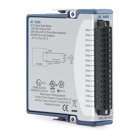
- Page 1 OPERATING INSTRUCTIONS NI 9485 8-Channel Solid-State Relay (SSR) Digital Output Module...
-
Page 2: Safety Guidelines
These operating instructions describe how to use the National Instruments 9485. For information about installing, configuring, and programming the system, refer to the system documentation. Visit ni.com/info to determine which software you need for the modules you are using. The safety guidelines and specifications in this Note document are specific to the NI 9485. -
Page 3: Safety Guidelines For Hazardous Voltages
You must use the NI 9939 connector backshell kit to ensure that the terminals are not accessible. © National Instruments Corp. /60 VDC), you must ensure that devices NI 9485 Operating Instructions... -
Page 4: Safety Guidelines For Hazardous Locations
Figure 1 shows the NI 9939 connector backshell. Figure 1. NI 9939 Connector Backshell Safety Guidelines for Hazardous Locations The NI 9485 is suitable for use in Class I, Division 2, Groups A, B, C, D, T4 hazardous locations; Class I, Zone 2, AEx nA II T4 and Ex nA II T4 hazardous locations;... - Page 5 (or supplies). The device must prevent the external power supply from exceeding 80 V if there is a transient overvoltage condition. © National Instruments Corp. NI 9485 Operating Instructions...
- Page 6 Special Conditions for Hazardous Locations Use in Europe This equipment has been evaluated as EEx nA II T4 equipment under DEMKO Certificate No. 03 ATEX 0324020X. The equipment is marked II 3G and is suitable for use in Zone 2 hazardous locations. Wiring the NI 9485 The NI 9485 has a 16-terminal, detachable screw-terminal connector that provides connections for eight solid-state relay...
- Page 7 Module © National Instruments Corp. Table 1. Terminal Assignments Terminal Signal CH0a CH0b CH1a CH1b CH2a CH2b CH3a CH3b CH4a CH4b CH5a CH5b CH6a CH6b CH7a CH7b NI 9485 Operating Instructions...
-
Page 8: Wiring For High-Vibration Applications
Wiring for High-Vibration Applications If an application is subject to high vibration, National Instruments recommends that you either use ferrules to terminate wires to the detachable screw-terminal connector or use the NI 9939 backshell kit to protect the connections. Refer to Figure 2 for an illustration. - Page 9 AC or DC power source. Figure 3 shows a possible configuration where the load is connected to the CHb terminal and the DC or AC power source. NI 9485 Figure 3. Connecting a Load to the NI 9485 © National Instruments Corp. Load – NI 9485 Operating Instructions...
-
Page 10: Protecting Inductive Loads
When you write an ON command to a channel, the SSR is closed and the terminal that is connected to the load allows current to flow or allows voltage to be applied to the load. When you write an OFF command to a channel, the switch opens, disconnecting the circuit so no current flows and no voltage is applied to the load. - Page 11 Figures 4 and 5 show examples of using an external flyback diode to protect DC inductive loads and an MOV to protect AC inductive loads, respectively. NI 9485 Figure 4. Contact Protection for DC Inductive Loads © National Instruments Corp. Flyback Diode for DC Inductive Loads Inductive Load –...
-
Page 12: Sleep Mode
NI 9485 Figure 5. Contact Protection for AC Inductive Loads Sleep Mode This module supports a low-power sleep mode. Support for sleep mode at the system level depends on the chassis that the module is plugged into. Refer to the chassis documentation for information about support for sleep mode. -
Page 13: Specifications
The following specifications are typical for the range –40 to 70 °C unless otherwise noted. Output Characteristics Number of channels... 8 digital output channels Relay type ... Normally open solid-state relay (SSR) Switching voltage ... 60 VDC max, 30 V © National Instruments Corp. NI 9485 Operating Instructions... - Page 14 Switching current, per channel All channels... 0.75 A max Up to four channels ... 1.2 A max Switching rate (90% duty cycle) Relay open time ... 0.5 ms typ Relay close time... 9.0 ms typ On resistance... 200 mΩ max Off state leakage ...
-
Page 15: Power Requirements
Screw-terminal wiring ... 12 to 24 AWG copper Ferrules ... 0.25 mm Torque for screw terminals ... 0.5 to 0.6 N · m Weight... Approx. 145 g (5.1 oz) © National Instruments Corp. conductor wire with 10 mm (0.39 in.) of insulation stripped from the end to 0.5 mm... - Page 16 Safety Safety Voltages Connect only voltages that are within these limits. Channel a-to-Channel b ... 60 VDC max, 30 V Isolation Channel-to-channel Continuous ... 60 VDC Withstand ... 1,390 V Channel-to-earth ground Continuous ... 250 V Withstand ... 2,300 V Measurement Category II is for measurements performed on circuits directly connected to the electrical distribution system.
- Page 17 Hazardous Locations U.S. (UL) ... Class I, Division 2, Canada (C-UL) ... Class I, Division 2, Europe (DEMKO)... EEx nA II T4 © National Instruments Corp. ni.com/certification Groups A, B, C, D, T4; Class I, Zone 2, AEx nA II T4 Groups A, B, C, D, T4;...
- Page 18 Environmental National Instruments C Series modules are intended for indoor use only but may be used outdoors if installed in a suitable enclosure. Refer to the installation instructions for the chassis you are using for more information about meeting these specifications.
-
Page 19: Shock And Vibration
• EN 55011 Emissions; Group 1, Class A • CE, C-Tick, ICES, and FCC Part 15 Emissions; Class A © National Instruments Corp. , 10 to 500 Hz 50 g, 3 ms half sine, 18 shocks at 6 orientations NI 9485 Operating Instructions... -
Page 20: Waste Electrical And Electronic Equipment (Weee)
For EMC compliance, operate this device Note according to product documentation. CE Compliance This product meets the essential requirements of applicable European Directives, as amended for CE marking, as follows: • 73/23/EEC; Low-Voltage Directive (safety) • 89/336/EEC; Electromagnetic Compatibility Directive (EMC) Refer to the Declaration of Conformity (DoC) for Note this product for any additional regulatory compliance... - Page 21 National Instruments Contact Information The National Instruments Web site is your complete resource for technical support. At you have access to ni.com/support everything from troubleshooting and application development self-help resources to email and phone assistance from NI Application Engineers. National Instruments corporate headquarters is located at 11500 North Mopac Expressway, Austin, Texas, 78759-3504.
- Page 22 Korea 82 02 3451 3400, Lebanon 961 (0) 1 33 28 28, Malaysia 1800 887710, Mexico 01 800 010 0793, Netherlands 31 (0) 348 433 466, New Zealand 0800 553 322, Norway 47 (0) 66 90 76 60, Poland 48 22 3390150, Portugal 351 210 311 210, Russia 7 495 783 6851, Singapore 1800 226 5886, Slovenia 386 3 425 42 00, South Africa 27 0 11 805 8197, Spain 34 91 640 0085,...
- Page 23 National Instruments, NI, ni.com, and LabVIEW are trademarks of National Instruments Corporation. Refer to the Terms of Use section on ni.com/legal for more information about National Instruments trademarks. Other product and company names mentioned herein are trademarks or trade names of their respective companies.