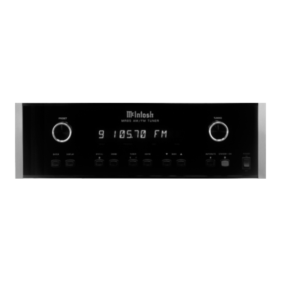
McIntosh MR85 Service Manual
Am/fm tuner, including tm1 tuner module option
Hide thumbs
Also See for MR85:
- Owner's manual (20 pages) ,
- Quick start manual (7 pages) ,
- Specifications (2 pages)
Table of Contents
Advertisement
Quick Links
INCLUDING TM1 TUNER MODULE OPTION
Performance Specifications ........................................ 2
Notes ......................................................................... 2
Rear Panel .................................................................. 3
Section Location ........................................................ 3
Block Diagram ........................................................... 4
Interconnection Diagram ...................................... 5 - 6
Power Supply Schematic and PCB ...................... 7 - 10
AM/FM TUNER
CONTENTS
SERVICE MANUAL
Display Schematic and PCB .............................. 11 - 16
Tuner Schematic and PCB ................................. 17 - 19
RAA1 Schematic and PCB ........................................ 20
Parts List ............................................................ 21 - 22
Exploded View and Parts List ............................. 24 - 26
Repacking Instructions ............................................. 27
Advertisement
Table of Contents

Summary of Contents for McIntosh MR85
-
Page 1: Table Of Contents
AM/FM TUNER INCLUDING TM1 TUNER MODULE OPTION CONTENTS Performance Specifications ........2 Display Schematic and PCB ......11 - 16 Notes ................. 2 Tuner Schematic and PCB ......... 17 - 19 Rear Panel ..............3 RAA1 Schematic and PCB ........20 Section Location ............ -
Page 2: Performance Specifications
230 Volts, 50/60Hz at 20 watts 75dB 240 Volts, 50/60Hz at 20 watts RF Intermodulation Note: Refer to the rear panel of the MR85 for the correct voltage. 65dB Dimensions Stereo Separation 17-1/2” (44.5cm) W, 5-3/8” (13.7cm) H, 17-1/2” (44.5cm) D,... -
Page 3: Rear Panel
MR85 REAR PANEL SECTION LOCATION TOP VIEW WITH COVER REMOVED... -
Page 4: Block Diagram
BLOCK DIAGRAM... - Page 5 MR85 INTERCONNECT...
- Page 6 2 POWER SUPPLY 049410...
- Page 7 MR85 2 POWER SUPPLY 049410...
- Page 8 3 DISPLAY 049409 1 0F 2...
- Page 9 MR85 DISPLAY 049409 2 0F 2...
- Page 10 DISPLAY 049409...
- Page 11 MR85 TUNER 049084...
- Page 12 TUNER RAA1 049084 049084...
-
Page 13: Parts List
TRANSISTOR NPN DAR MPSA25 133366 IC 8 BIT A/D SERIAL OUTPUT 132223 TRANSISTOR NPN MPS4124 2K/REEL Q2 Q3 133408 PROGRAMMED MICRO MR85 V1.00 IC14 133114 IC AUDIO PROCESSOR 137042 FLAMEPROOF RES 47 OHM 5% 1/4W 133119 IC REGULATOR +12 VOLT... -
Page 14: Parts List
PARTS LIST 144351 1.74K 1% 1/4W MF RES 133189 IC OPERATIONAL AMPLIFIER IC4 IC5 144366 RES NETWORK ISOLATED 2X22K 133231 LA1175 FM FRONT END 150058 TACT SWITCH S1 S2 S3 S4 133270 IC DIRECT PLL FREQ SYNTHESIZER S5 S6 S7 S8 133381 AM-FM MPX TUNER IC S9 S10... - Page 15 MR85 NOTES...
-
Page 16: Exploded View And Parts List
EXPLODED VIEW PARTS LIST Ref. Part Description 016419 FRONT GLASS 171320 C/A SWITCH 017531 PUSHBUTTON ASSY RED 017517 PUSHBUTTON ASSY 078033 O-RING 049411 KNOB ASSY 104073 BLK FELT WASHER 018611 5” ENDCAP 101042 TS 4-40 X 1/2 SLOT FILLISTER 094360 FOAM TAPE 1/2 X1/2 004810 EXTRUSION BRACKET 5”... - Page 17 EXPLODED VIEW...
-
Page 18: Repacking Instructions
SERVICE MANUAL The continuous improvement of it’s products is the policy of McIntosh Laboratory Incorporated, who reserve the right to improve design without notice. Because of the constant upgrading of McIntosh products’ circuitry and components, the Company cannot insure, and does not warrant, the accuracy of the within schematic material, which is intended for information only.


