McIntosh MR 73 Owner's Manual
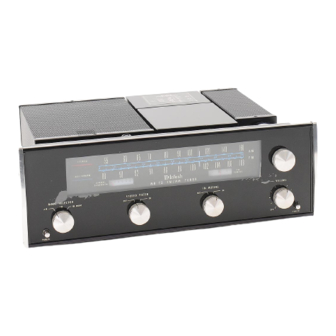
Solid state fm/fm stereo-am tuner
Hide thumbs
Also See for MR 73:
- Owner's manual (20 pages) ,
- Service information (25 pages) ,
- Service information (25 pages)
Table of Contents
Advertisement
Quick Links
Advertisement
Table of Contents

Related Manuals for McIntosh MR 73


Summary of Contents for McIntosh MR 73
- Page 1 THE McINTOSH MR 73 SOLID STATE FM/FM STEREO-AM TUNER Price $1.25...
-
Page 2: Customer Service
The dealers carefully. Only one dealer in ten SERVICE CONTRACT does not cover any qualifies for a McIntosh franchise. To receive shipping costs to and from the authorized the SERVICE CONTRACT your purchase must service agency or the factory. -
Page 3: If You're In A Hurry
If You're in a Hurry MULTIPATH INDICATOR — Fluctuating display indicates FM TUNING —Tune FM until the multipath distortion. Rotate indicator is in the black area in antenna for minimum fluctuation. the center of the meter face. STEREO INDICATOR —Lights when station is transmitting stereo pilot carrier for stereo broadcasting. -
Page 4: Installation
Allow at least 15 inches deep x 17½ inches wide x6 inches high for mounting the MR 73. Always allow for air flow by either ventilation holes or space next to the bottom of the tuner and a means for a warm air to escape at the top. -
Page 5: Vertical Installation
Insert the power cord through the opening. Care- fully slide the MR 73 into the opening so the rails on the bottom of the equipment slide in the track DO NOT USE THE SPRINGS ON HORIZONTALLY of the mounting brackets. -
Page 6: How To Connect
FM antenna, or (2) a VHF-TV antenna, used. Set the AM ANT slide switch on the MR 73 or (3) the indoor dipole supplied with the MR 73. back panel to the LOOP position. -
Page 7: Back Panel Information
Back Panel Information AM ANT SWITCH Adjust the MR 73 AM ANT switch to match the particular type of AM antenna used. EXT. position is for a conventional antenna, usually of the out- door type, from 50 to 150 feet in length. LOOP TP1 and TP2 position is for the built-in Ferrite Loopstick. -
Page 8: Front Panel Information
When the INDICATORS station switches to stereo broadcast, the The MR 73 has four indicators on the dial panel: stereo indicator will light and the MR 73 STEREO indicator, MULTIPATH indicator, SIGNAL will automatically switch to stereo opera- STRENGTH meter, and the TUNING meter. - Page 9 Turn the MODE SELECTOR to FM MONO to MUTING listen only to monophonic FM. If you wish to have the MR 73 automatically The MR 73 ultrasonic muting circuit suppresses switch to a stereo broadcast, set the MODE SE- all noise between stations. It suppresses all weaker LECTOR to FM.
- Page 10 RF selectivity and excellent Each of the two integrated circuits used in spurious response rejection. The problem of the FM-IF of the MR 73 contain 16 transistors, image rejection has been greatly reduced in 3 zener diodes, 5 diodes and 23 resistors, all the RF section of the MR 73.
-
Page 11: Power Supply
L + R main carrier MOSFET. The use of MOSFET's in the RF amplifier signal. This yields the left and right program and mixer provides the MR 73 with very little cross output with maximum separation. modulation (spurious response) and the image re- The 19 kHz pilot signal is filtered from the jection is very good. -
Page 12: Performance Limits
Performance Limits are the maximum deviation from perfection permitted for a McIntosh instru- AUTOMATIC MONO-STEREO SWITCH: Mclntosh ment. We promise you that the MR 73 you buy developed; all electronic automatic mono- must be capable of performance at or exceeding stereo switching circuit. -
Page 13: Performance Charts
FREQUENCY IN kHz -300 -200 -100 Performance Charts - 1 0 - 2 0 - 3 0 - 4 0 - 5 0 - 6 0 - 7 0 FREQUENCY IN HERTZ IF AMPLITUDE RESPONSE 1000 10000 20000 HARMONIC DISTORTION 1µV 1µV 10µV... - Page 15 McINTOSH LABORATORY INC. 2 CHAMBERS ST., BINGHAMTON, N. Y. 13903 607-723-3512 Design subject to change without notice. Primed in U.S.A. 038-448...