
Related Manuals for Fujitsu ASYG09LTCB


Summary of Contents for Fujitsu ASYG09LTCB
-
Page 1: Wall Mounted Type
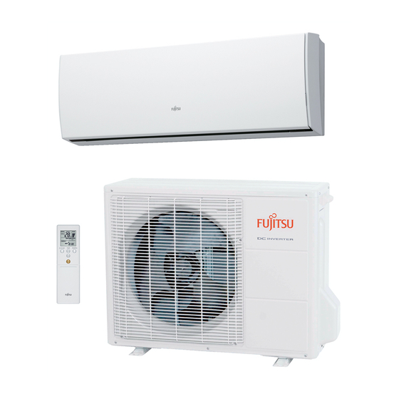
AIR CONDITIONER Wall Mounted type DESIGN & TECHNICAL MANUAL INDOOR AS G09LTCB AS G12LTCB AS G14LTCB OUTDOOR AO G09LTCN AO G12LTCN AO G14LTCN... -
Page 2: Indoor Unit
1. INDOOR UNIT WALL MOUNTED TYPE : AS G09LTCB AS G12LTCB AS G14LTCB DTR_AS057E_01 2011.09.21... -
Page 3: Table Of Contents
CONTENTS 1. INDOOR UNIT 1. FEATURE ........................01 - 01 2. WIRELESS REMOTE CONTROLLER ..........01 - 04 3. SPECIFICATIONS ....................01 - 06 4. DIMENSIONS ......................01 - 07 5. WIRING DIAGRAMS ..................01 - 09 6. CAPACITY TABLE .................... -
Page 4: Feature
FEATURE MODEL AS G09LTCB / AO G09LTCN AS G12LTCB / AO G12LTCN AS G14LTCB / AO G14LTCN AO G09LTCN AO G12LTCN AO G14LTCN FEATURES Energy-Efficiency classification A Europe Energy-Efficiency classification A achieved Thin & Slim design Thin and slim design is realized by Ø5mm heat Big open panel and High density multi path heat exchanger and high efficiency wind blower. -
Page 5: Powerful Operation
Powerful heating at low outdoor temperature Keeping the high heating capacity at low outdoor temperature. NEW model Current model * : ASYA09LEC (09 Class) 14%up ASYA12LEC (12 Class) Heating capacity 13%up (kW) 15%up 09 Class -15°C -7°C 2°C Outdoor temperature 12%up 23%up 38%up... -
Page 6: Economy Operation
High energy saving High COP is realized by using Large heat exchanger, DC rotary compressor, and inverter technology. 14%up! 7%up! 4.85 4.40 4.27 4.12 3.91 LT series LE series Class Class Class Energy saving control Human sensor catches movements of people in a room, and operates with lower capacity when the room is empty. -
Page 7: Wireless Remote Controller
WIRELESS REMOTE CONTROLLER FEATURES 3 Mode timer setup (Weekly / Program / Sleep) are possible. Easy operation. Easy to change signal code (4 patterns) by button operation. Built-in timers Select from Three different timer programs (Weekly / Program / Sleep). Weekly timer Weekly timer can be easily set by wireless remote controller. - Page 8 FUNCTIONS SENSOR button Signal Transmitter MODE button FAN button 10 °C HEAT button ECONOMY button SWING button TEMP. button OUTDOOR UNIT SET button LOW NOISE button POWERFUL button WEEKLY button TIMER SETTING button START/STOP ON/OFF button SEND button button SLEEP button SELECT button RESET button NEXT button...
-
Page 9: Specifications
SPECIFICATIONS WALL MOUNTED Type INVERTER HEAT PUMP Model name AS G09LTCB AS G12LTCB AS G14LTCB Power source 230V~ 50Hz Available voltage range 198-264V~ 50Hz Cooling European energy label Heating 2.50 3.50 4.20 Rated Btu/h 8,500 11,900 14,300 Cooling 0.9-3.5 1.1-4.0 0.9-5.4 Min-Max Btu/h... -
Page 10: Dimensions
DIMENSIONS MODEL : AS G09LT, AS G12LT, AS G14LT (Unit : mm) 187: Installed state - (01 - 07) -... - Page 11 INSTALLATION PLACE (Unit : mm) - (01 - 08) -...
-
Page 12: Wiring Diagrams
WIRING DIAGRAMS MODEL : AS G09LT, AS G12LT, AS G14LT - (01 - 09) -... -
Page 13: Capacity Table
CAPACITY TABLE 6-1. COOLING CAPACITY MODEL : AS G09LT 13.3 Indoor temperature °CDB °CWB °CDB 2.34 1.62 0.35 2.61 1.63 0.36 2.70 1.77 0.36 2.87 1.78 0.37 2.96 1.92 0.37 3.14 1.91 0.37 3.32 2.04 0.37 2.22 1.54 0.40 2.48 1.55 0.40 2.56... -
Page 14: Heating Capacity
6-2. HEATING CAPACITY MODEL : AS G09LT 13.3 Indoor temperature (°CDB) (°CDB) (°CWB) 2.31 1.17 2.26 1.19 2.20 1.21 2.15 1.24 2.09 1.26 2.84 1.24 2.77 1.26 2.70 1.29 2.63 1.32 2.57 1.34 3.36 1.31 3.28 1.34 3.20 1.37 3.12 1.39 3.04 1.42... -
Page 15: Fan Performance
FAN PERFORMANCE 7-1. AIR VELOCITY DISTRIBUTION Note: Fan speed : High MODEL : AS G09LT Operation mode : FAN Unit : m/s TOP VIEW Vertical flap : Up Horizontal flap : Center Unit : m/s TOP VIEW Vertical flap : Up Horizontal flap : Right &... - Page 16 Note: Fan speed : High MODEL : AS G12LT Operation mode : FAN Unit : m/s TOP VIEW Vertical flap : Up Horizontal flap : Center Unit : m/s TOP VIEW Vertical flap : Up Horizontal flap : Right & Left Unit : m/s SIDE VIEW Vertical flap : Up...
- Page 17 Note: Fan speed : High MODEL : AS G14LT Operation mode : FAN Unit : m/s TOP VIEW Vertical flap : Up Horizontal flap : Center Unit : m/s TOP VIEW Vertical flap : Up Horizontal flap : Right & Left Unit : m/s SIDE VIEW Vertical flap : Up...
-
Page 18: Air Flow
7-2. AIR FLOW MODEL : AS G09LT Cooling Number of Fan speed rotations Air flow (r.p.m.) HIGH 1300 1080 QUIET Heating Number of Fan speed rotations Air flow (r.p.m.) HIGH 1300 1120 QUIET - (01 - 15) -... - Page 19 MODEL : AS G12LT Cooling Number of Fan speed rotations Air flow (r.p.m.) HIGH 1370 1120 QUIET Heating Number of Fan speed rotations Air flow (r.p.m.) HIGH 1370 1180 QUIET - (01 - 16) -...
- Page 20 MODEL : AS G14LT Cooling Number of Fan speed rotations Air flow (r.p.m.) HIGH 1440 1220 QUIET Heating Number of Fan speed rotations Air flow (r.p.m.) HIGH 1510 1220 1030 QUIET - (01 - 17) -...
-
Page 21: Operation Noise
OPERATION NOISE 8-1. NOISE LEVEL CURVE MODEL : AS G09LT Cooling Cooling Heating Heating NC-65 NC-65 NC-60 NC-60 NC-55 NC-55 NC-50 NC-50 NC-45 NC-45 NC-40 NC-40 NC-35 NC-35 NC-30 NC-30 NC-25 NC-25 NC-20 NC-20 NC-15 NC-15 1,000 1,000 2,000 2,000 4,000 4,000 8,000... - Page 22 MODEL : AS G14LT Cooling Heating NC-65 NC-65 NC-60 NC-60 NC-55 NC-55 NC-50 NC-50 High High NC-45 NC-45 NC-40 NC-40 NC-35 NC-35 NC-30 NC-30 NC-25 NC-25 Quiet Quiet NC-20 NC-20 NC-15 NC-15 1,000 2,000 4,000 8,000 1,000 2,000 4,000 8,000 Octave band center frequency,Hz Octave band center frequency,Hz - (01 - 19) -...
-
Page 23: Sound Level Check Point
8-2. SOUND LEVEL CHECK POINT - (01 - 20) -... -
Page 24: Electric Characteristics
ELECTRIC CHARACTERISTICS Model name AS G09LT AS G12LT AS G14LT Voltage 230~ Power supply Frequency Max. operating current Connection cable *1)Wiring Spec. Limited wiring length *1) Wiring Spec. Selected Sample (Selected based on Japan Electrotechnical Standard and Codes Committee E0005) - (01 - 21) -... -
Page 25: Safety Devices
SAFETY DEVICES Model Protection form AS G09LT AS G12LT AS G14LT Circuit protection Current fuse (PCB) 3.15A 250V Terminal protection Current (thermal) fuse 3A 250V °C OFF Fan motor protection Thermal protector program °C ON - (01 - 22) -... -
Page 26: External Input & Output
EXTERNAL INPUT & OUTPUT Connector INPUT OUTPUT REMARKS CNA01 Control input See external CNB01 Operation status output input/output settings for details. CNB02 Error status output 11-1. EXTERNAL INPUT CONTROL INPUT (Operation/Stop or Forced stop) The air conditioner can be remotely operated by means of the following on-site work. "Operation/Stop"... - Page 27 When function setting is "Forced stop" mode Input signal Forced stop Command Normal Operation Indoor unit Stop Remote controller Remote control operation invalidity Parts (Optional) Parts name Model name External connect kit UTY-XWZXZ5 Communication kit UTY-TWBXF * For operating the EXTERNAL function, the Compact wall mounted type requires the communication kit in addition to the wire (UTY-XWZXZ5).
-
Page 28: External Output
11-2. EXTERNAL OUTPUT OPERATION STATUS OUTPUT An air conditioner operation status signal can be output. Circuit diagram example Indoor control PC board Communication kit Connected unit Connector 24V DC Ex.)Relay unit Ex.)Display Relay power supply *10 m Signal Optional parts Field supply * Make the distance from the PC board to the connected unit within 10m. - Page 29 ERROR STATUS OUTPUT An air conditioner error status signal can be output. Circuit diagram example Indoor control PC board Communication kit Connected unit Connector 24V DC Ex.)Relay unit Ex.)Display Relay power supply *10 m Signal Optional parts Field supply * Make the distance from the PC board to the connected unit within 10m. Relay spec.
-
Page 30: Function Setting
FUNCTION SETTING 12-1. INDOOR UNIT (Setting by remote controller) • The function settings of the control of the indoor unit can be changed by this procedure according to the installation conditions. Incorrect settings can cause the indoor unit malfunction. • After the power is turned on, perform the “FUNCTION SETTING”... -
Page 31: Function Details
FUNCTION DETAILS Compact wall Functions mounted 1) Filter sign 2) Cooler room temperature correction 3) Heater room temperature correction 4) Auto restart Indoor room temperature sensor switching function 6) Remote controller signal code 7) External input control 1) Filter sign The indoor unit has a sign to inform the user that it is time to clean the filter. - Page 32 4) Auto restart Enable or disable automatic system restart after a power outage. ( ... Factory setting) Setting description Function number Setting value * Auto restart is an emergency function such as for power failure etc. Do not start and stop the indoor unit by this function in normal operation. Be sure to operate by the control unit, or external input device.
- Page 33 REMOTE CONTROLLER SIGNAL CODE SETTING Use the following steps to select the signal code of the remote controller. (Note that the air conditioner cannot receive a signal code if the air conditioner has not been set for the signal code.) (1) Press the START/STOP ( / ) button until only the clock is displayed on the remote controller display.
-
Page 34: Optional Parts
OPTIONAL PARTS Exterior Parts name Model No. Summary Unit control is performed by Wired remote wired remote controller. UTY-RNNYM *Optional communication kit is controller necessary for the installation. Unit control is performed by Simple remote simple remote controller. UTY-RSNYM controller *Optional communication kit is necessary for the installation. -
Page 35: Outdoor Unit
2. OUTDOOR UNIT SINGLE TYPE : AO G09LTCN AO G12LTCN AO G14LTCN DTR_AO092E_01 2011.09.21... - Page 36 CONTENTS 2. OUTDOOR UNIT 1. SPECIFICATIONS ....................02 - 01 2. DIMENSIONS ......................02 - 02 3. REFRIGERANT CIRCUIT ................02 - 04 4. WIRING DIAGRAMS ..................02 - 06 5. CAPACITY COMPENSATION RATE FOR PIPE LENGTH AND HEIGHT DIFFERENCE ..............
-
Page 37: Specifications
SPECIFICATIONS Type INVERTER HEAT PUMP Model name AO G09LTCN AO G12LTCN AO G14LTCN Power sourse 230V ~ 50Hz Available voltage range 198-264V ~ 50Hz Starting current Cooling 1,700 2,050 Airflow rate Heating 1,700 2,000 Type×Q'ty Propeller fan×1 Motor output Cooling Sound pressure level dB(A) Heating... -
Page 38: Dimensions
DIMENSIONS MODEL : AO G09LT (Unit : mm) Top view Front view Side view Air flow 17.5 hole (10) (10) (10) hole (6x20=120) (6x20=120) ø20 hole 4-ø11.3mm hole Bottom view INSTALLATION PLACE CAUTION In the area with heavy snowfall, if the intake and outlet of outdoor unit is blocked with snow, it might become difficult to get warm and it is likely to cause of the break- down. - Page 39 MODEL : AO G12LT, AO G14LT (Unit : mm) Top view Side view Front view Air flow 17.5 hole (10) (10) (10) hole (6x20=120) (6x20=120) ø20 hole 4-ø11.3mm hole Bottom view INSTALLATION PLACE CAUTION In the area with heavy snowfall, if the intake and outlet of outdoor unit is blocked with snow, it might become difficult to get warm and it is likely to cause of the break- down.
-
Page 40: Refrigerant Circuit
REFRIGERANT CIRCUIT MODEL : AO G09LT, AO G12LT Heat exchanger Sub heat exchanger 3-Way ( INDOOR ) valve 2-Way valve Muffler 4-Way valve Strainer Expansion valve Heat exchanger Strainer ( OUTDOOR ) Cooling Heating Refrigerant pipe diameter Liquid : 1/4" (6.35 mm) Gas : 3/8"... - Page 41 MODEL : AO G14LT Heat exchanger Sub heat exchanger 3-Way ( INDOOR ) valve 2-Way valve Muffler Muffler Receiver tank 4-Way valve Strainer Expansion valve Heat exchanger Strainer ( OUTDOOR ) Cooling Heating Refrigerant pipe diameter Liquid : 1/4" (6.35 mm) Gas : 1/2"...
-
Page 42: Wiring Diagrams
WIRING DIAGRAMS MODEL : AO G09LT, AO G12LT - (02 - 06) -... - Page 43 MODEL : AO G14LT - (02 - 07) -...
-
Page 44: Capacity Compensation Rate For Pipe Length And Height Difference
CAPACITY COMPENSATION RATE FOR PIPE LENGTH AND HEIGHT DIFFERENCE MODEL : AO G09LT Pipe length (m) COOLING 0.858 0.868 0.929 0.872 0.882 Indoor unit is upper than 0.960 0.933 0.876 0.885 outdoor unit. 0.992 0.964 0.937 0.879 0.889 Height difference H 1.000 0.972 0.944... - Page 45 MODEL : AO G12LT Pipe length (m) COOLING 0.893 0.909 0.955 0.908 0.924 Indoor unit is upper than 0.975 0.959 0.912 0.928 outdoor unit. 0.992 0.979 0.963 0.916 0.931 Height difference H 1.000 0.987 0.970 0.923 0.939 1.000 0.987 0.970 0.923 0.939 -7.5...
- Page 46 MODEL : AO G14LT Pipe length (m) COOLING 0.951 0.950 0.979 0.967 0.966 Indoor unit is upper than 0.988 0.983 0.971 0.970 outdoor unit. 0.994 0.992 0.987 0.975 0.974 Height difference H 1.002 1.000 0.995 0.983 0.982 1.002 1.000 0.995 0.983 0.982 -7.5...
-
Page 47: Additional Charge Calculation
ADDITIONAL CHARGE CALCULATION MODEL : AO G09LT Refrigerant type R410A Refrigerant amount 1050 Refrigerant charge Total pipe length 15 or less 20 (MAX) 20g/m Additional charge MODEL : AO G12LT Refrigerant type R410A Refrigerant amount 1200 Refrigerant charge Total pipe length 15 or less 20 (MAX) 20g/m... -
Page 48: Air Flow
AIR FLOW MODEL : AO G09LT Cooling Number of rotations Air flow (r.p.m.) 1700 1000 Heating Number of rotations Air flow (r.p.m.) 1700 1000 MODEL : AO G12LT, AO G14LT Cooling Number of rotations Air flow (r.p.m.) 2050 1206 Heating Number of rotations Air flow... -
Page 49: Operation Noise
OPERATION NOISE 8-1. NOISE LEVEL CURVE MODEL : AO G09LT Cooling Heating NC-65 NC-65 NC-60 NC-60 NC-55 NC-55 NC-50 NC-50 NC-45 NC-45 NC-40 NC-40 NC-35 NC-35 NC-30 NC-30 NC-25 NC-25 NC-20 NC-20 NC-15 NC-15 1,000 2,000 4,000 8,000 1,000 2,000 4,000 8,000 Octave band center frequency,Hz... - Page 50 MODEL : AO G14LT Cooling Heating NC-65 NC-65 NC-60 NC-60 NC-55 NC-55 NC-50 NC-50 NC-45 NC-45 NC-40 NC-40 NC-35 NC-35 NC-30 NC-30 NC-25 NC-25 NC-20 NC-20 NC-15 NC-15 1,000 2,000 4,000 8,000 1,000 2,000 4,000 8,000 Octave band center frequency,Hz Octave band center frequency,Hz - (02 - 14) -...
-
Page 51: Sound Level Check Point
8-2. SOUND LEVEL CHECK POINT - (02 - 15) -... -
Page 52: Electric Characteristics
ELECTRIC CHARACTERISTICS Model name AO G09LT AO G12LT AO G14LT Voltage 230 ~ Power supply Frequency *1) Max operating current 10.0 11.5 14.5 Starting Current Main Fuse (Circuit breaker) Current *2) Wiring Spec.: Power Cable 3.5-4.0 *3) Limited wiring length : *1) The maximum current is the total current of indoor unit and outdoor unit. -
Page 53: Safety Devices
SAFETY DEVICES Model Protection form AO G09LT AO G12LT AO G14LT Current fuse ― 20A 250V (NEAR THE TERMINAL) Circuit protection Current fuse 20A 250V 10A 250V (MAIN PRINTED CIRCUIT BOARD) 5A 250V 3.15A 250V Thermal protection OFF : 150°C OFF : 100±10°C Fan motor protection program...