Table of Contents
Advertisement
INSTALLATION
INSTRUCTIONS
READ ALL INSTRUCTIONS CAREFULLY BEFORE
BEGINNING THE INSTALLATION.
THE INSTALLATION MUST COMPLY WITH THESE
INSTRUCTIONS AND THE REQUIREMENTS OF ALL
GOVERNING CODES AND ORDINANCES FOR THE
INSTALLATION LOCATION.
IT IS THE RESPONSIBILITY OF INSTALLER TO KNOW
AND UNDERSTAND ALL OF THESE REQUIREMENTS.
FAILURE TO DO SO COULD CREATE A HAZARD
RESULTING IN PROPERTY DAMAGE, BODILY INJURY,
OR DEATH.
© Copyright 2004
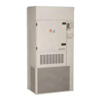
WG - SERIES
COMBINATION GAS/ELECTRIC
WALL-MOUNT
WG242
WG423
WARNING
Bard Manufacturing Company, Inc.
Bryan, Ohio 43506
Since 1914...Moving ahead just as planned.
MODELS:
WG302
WG362
WG482
WG602
Manual No.:
Supersedes:
File:
Date:
2100-365M
2100-365L
Volume III, Tab 20
05-25-06
Manual 2100-365M
Page
1 of 74
Advertisement
Table of Contents

Related Manuals for Bard WG242


Summary of Contents for Bard WG242
-
Page 1: Installation Instructions
AND UNDERSTAND ALL OF THESE REQUIREMENTS. FAILURE TO DO SO COULD CREATE A HAZARD RESULTING IN PROPERTY DAMAGE, BODILY INJURY, OR DEATH. Manual No.: 2100-365M Bard Manufacturing Company, Inc. Supersedes: 2100-365L Bryan, Ohio 43506 File: Volume III, Tab 20 Since 1914...Moving ahead just as planned. -
Page 2: Table Of Contents
CONTENTS Page Page 20. Checking Gas Input Rate ......... 25 Getting Other Information and Publications ....4 21. Standard Orifice Sizing & High WG Series Model Nomenclature ....... 5 Altitude Derate ..........27 Ventilation Options ............ 5 22. Conversion of Gas Input BTUH From High Air Conditioning Module Options ....... - Page 3 Table 9 Motor Speed Taps ........37 Figure 10 Installation of Flexible Conduit ..... 21 Table 10 WG242 Indoor Blower Performance ..40 Figure 11 Low Voltage Wiring ......22 Table 11 WG302 Indoor Blower Performance ..41 Figure 12 Gas Pipe Connection ......23 Table 12 WG362 Indoor Blower Performance ..
-
Page 4: Getting Other Information And Publications
Equipment Selection Telephone: (416) 447-4044 Canadian Electrical Code ......CSA C22.1 Canadian Installation Code CAN/CGA B149 COPYRIGHT SEPTEMBER 2003 BARD MANUFACTURING COMPANY BRYAN, OHIO 43506 USA Manufactured under the following U.S. patent numbers: 5,485,878; 5,002,116; 4,924,934; 4,875,520; 4,4825,936 Manual 2100-365M Page... -
Page 5: Wg Series Model Nomenclature
WALL MOUNT GAS/ELECTRIC GENERAL MODEL NUMBER NOMENCLATURE – REVISION VENT COLOR MODEL CONTROL OPTIONS X = Beige See Table Below Wall Mount Gas/Electric (See Table page 6) (Standard) VOLTAGE 4 = Gray A = 230/208-60-1 COOLING CAPACITY COIL OPTIONS B = 230/208-60-3 24 = 2 ton X = Standard C = 460-60-3... -
Page 6: Air Conditioning Module Options
AIR CONDITIONING MODULE OPTIONS STD = Standard equipment. CCM Compressor control module has adjustable 30 second to 5 minute delay-on-break timer. On initial power up, or any time the power is interrupted, the delay-on-make will be 2 minutes plus 10% of the delay-on-break setting. There is no delay-on- make during routine operation of the unit. -
Page 7: Table 1 Specifications - Wg24-36 Models
Manual 2100-365M Page 7 of 74... -
Page 8: Table 1A Specifications - Wg42-60 Models
Manual 2100-365M Page 8 of 74... -
Page 9: Figure 1 Unit Dimensions
Manual 2100-365M Page 9 of 74... -
Page 10: High Altitude Applications
Any grille that meets with the 5/8 inch louver criteria on heat loss/heat gain calculations made according to may be used. It is recommended that Bard Return Air methods of Air Conditioning Contractors of America Grille or Return Filter Grille be installed when no (ACCA). -
Page 11: Wall Mounting
7. WALL MOUNTING INFORMATION WARNING 1. Two holes for the supply and return air openings must be cut through the wall as detailed in Figure 4. Failure to provide the one inch clearance 2. On wood-frame walls, the wall construction between the supply duct and a combustible must be strong and rigid enough to carry the surface for the first three feet of duct can... -
Page 12: Figure 2 Mounting Instructions - Wg24-36
Manual 2100-365M Page 12 of 74... -
Page 13: Figure 2A Mounting Instructions - Wg42-60
Manual 2100-365M Page 13 of 74... -
Page 14: Figure 3 Combustible Clearance - Wg24-36
FIGURE 3 COMBUSTIBLE CLEARANCE FOR WG24, WG30 AND WG36 MODELS FIGURE 3A COMBUSTIBLE CLEARANCE FOR WG42, WG48 AND WG60 MODELS WARNING A minimum of one (1) inch clearance must be maintained between the supply air duct and combustible materials. This is required for the first three (3) feet of ducting. It is important to insure that the one (1) inch minimum spacing is maintained at all points. -
Page 15: Figure 4 Wall Mounting Instructions
FIGURE 4 WALL MOUNTING INSTRUCTIONS FIGURE 5 WALL MOUNTING INSTRUCTIONS Manual 2100-365M Page 15 of 74... -
Page 16: Figure 6 Common Wall Mounting Installations
FIGURE 6 COMMON WALL MOUNTING INSTALLATIONS Manual 2100-365M Page 16 of 74... -
Page 17: Clearances
9. CLEARANCES TABLE 2 MINIMUM INSTALLATION CLEARANCES Minimum clearances, as specified in Table 2, must be maintained from adjacent structures to provide t e l ) s l r i f adequate fire protection, adequate combustion air, and ) s l room for service personnel. -
Page 18: Vent Terminal And Combustion Inlet Hood
11. OPTIONAL VERTICAL VENTING 10. VENT TERMINAL AND COMBUSTION AIR INLET HOOD With the optional vertical venting kit (VVK-5) this unit may be vented vertically through a roof or overhang. The vent terminal is shipped in the burner The kit includes a stainless steel transition drain tee, compartment. -
Page 19: Vent Resizing Instructions
12. VENT RESIZING INSTRUCTIONS 13. FRESH AIR INTAKE All units are built with fresh air inlet slots punched in When an existing furnace is removed from a venting the service panel. system servicing other appliances, the venting system is likely to be too large to properly vent the remaining If the unit is equipped with a fresh air damper attached appliances. -
Page 20: Wiring - Main Power
15. WIRING – MAIN POWER ELECTRICAL GROUNDING When installed, the furnace must be electrically WARNING grounded in accordance with local codes or in the absence of local codes, with the National Electrical Code, ANSI/NFPA 70, or Canadian Electrical Code, CSA22.1, latest edition. Use a copper wire from green For your personal safety, turn off electric ground wire on the furnace to a grounded connection in power at service entrance panel before... -
Page 21: Wiring - Low Voltage Wiring
FIGURE 10 INSTALLATION OF FLEXIBLE CONDUIT Direct Digital Controls (DDC) 16. WIRING – LOW VOLTAGE WIRING For total and proper control using DDC, a total of 5 Low Voltage Connection controlled outputs are required (4 if no ventilation is These units use a 24-volt AC low voltage circuit. installed). -
Page 22: Figure 11 Low Voltage Wiring
FIGURE 11 LOW VOLTAGE WIRING Manual 2100-365M Page 22 of 74... -
Page 23: Figure 12 Gas Pipe Connection
FIGURE 12 GAS PIPE CONNECTION Manual 2100-365M Page 23 of 74... -
Page 24: Gas Supply And Piping
18. GAS SUPPLY AND PIPING 8. Refer to Table 6 for Gas Pipe Sizes for natural gas. If more than one appliance is supplied from a single line size, capacity must equal or exceed the GENERAL RECOMMENDATIONS combined input to all appliances, and the branch 1. -
Page 25: Manifold Pressure Adjustment
5. Slowly open equipment shut off valve in gas supply PROPANE (LP) GAS CONVERSION line just ahead of furnace. Start furnace following “Operating Instructions” on front door. This unit may be converted in the field for 6. Slowly open 1/8" NPT manual shut off valve leading use with Propane (LP) gas. - Page 26 NATURAL GAS INPUT RATE 9. If you left water heater, dryer or range pilots on, allow for them in calculating correct furnace gas Natural gas heating value (BTU/cu. ft.) can vary input. A quick way is to allow 1,000 BTU per hour significantly.
-
Page 27: Standard Orifice Sizing & High Altitude Derate
21. STANDARD ORIFICE SIZING AND It is the installer’s responsibility to see that the furnace HIGH ALTITUDE DERATE input rate is adjusted properly. Derating must be achieved by reducing the size of the main burner This furnace is shipped with fixed gas orifices for use orifices. - Page 28 TABLE 8 NATURAL GAS ORIFICE TABLES FOR MODELS WG24, WG30 AND WG36 f i r f i r i t l c t i f i r f i r f i r f i r i t l c t i f i r f i r , y r...
-
Page 29: Table 8A Natural Gas Orifice Tables - Wg42-60
TABLE 8A NATURAL GAS ORIFICE TABLES FOR MODELS WG42, WG48 AND WG60 f i r f i r i t l c t i f i r f i r f i r f i r i t l c t i f i r f i r , y r... -
Page 30: Conversion Of Gas Input Btuh From High To Low Rating
22. CONVERSION OF GAS INPUT BTUH 2. Set balancing dampers in supply duct system. FROM HIGH TO LOW RATING 3. Check duct work for obstructions or leaks. All the derated WG series units are produced with 4. Make sure filters are clean and in place. maximum BTUH input orifices installed. -
Page 31: Filters
FIGURE 14 ACCESS INTERNAL FILTER THROUGH UPPER SERVICE DOOR 24. FILTERS HIGH PRESSURE SWITCH AND LOCKOUT SEQUENCE (Standard Feature) A 2" thick throwaway filter is supplied with each unit. This filter is installed by opening the main service door. If the high pressure switch opens, the compressor contactor will de-energize immediately. - Page 32 ALARM OUTPUT PHASE MONITOR Alarm terminal is output connection for applications All units with three phase scroll compressors are where alarm signal is desired. This terminal is powered equipped with a three phase line monitor to prevent whenever compressor is locked out due to HPC or LPC compressor damage due to phase reversal.
-
Page 33: Lighting & Shutdown Instructions
26. LIGHTING AND SHUTDOWN INSTRUCTIONS FIGURE 15 INSTRUCTION LABEL Manual 2100-365M Page 33 of 74... -
Page 34: Service Agency Procedures
FIGURE 16 27. SERVICE AGENCY PROCEDURES TOP VIEW OF GAS CONTROL CAUTION Label all wires prior to disconnection when servicing controls. Wiring errors can cause improper and dangerous operation. Verify proper operation after servicing. WARNING Follow these procedures before inspecting MIS-165 furnace. -
Page 35: Replacement Parts
ROUTINE MAINTENANCE WARNING 1. Air Filters – Check the condition at least monthly when the unit is in use, and replace as necessary. 2. Lubrication Requirements – The indoor circulating Disconnect electrical power before servicing unit. Failure to do so could result in electrical air blower motor and outdoor circulating air fan shock or death. -
Page 36: Sequence Of Operation - Heating
burner orifices or incorrect manifold pressure, 30. SEQUENCE OF OPERATION – insufficient combustion air, or installation deficiencies HEATING with respect to return air duct design or sizing. On a call for heat from the thermostat, the induced draft Once the problem has been resolved, reset the switch by blower is energized. -
Page 37: Indoor Blower Operation
FIGURE 18 FURNACE CONTROL BOARD AND BLOWER CONTROL 460 VOLT BLOWER MOTOR SPEED CHANGE 32. INDOOR BLOWER OPERATION Field changeover from the factory blower motor speed All models have multiple speed direct drive blower settings can require change several different motor motors. - Page 38 FIGURE 19 460 VOLT BLOWER MOTOR WIRING OPTIONS WG24, WG30 AND WG36 MODELS Manual 2100-365M Page 38 of 74...
- Page 39 FIGURE 20 460 VOLT BLOWER MOTOR WIRING OPTIONS WG42, WG48 AND WG60 MODELS Manual 2100-365M Page 39 of 74...
-
Page 40: Table 10 Wg242 Indoor Blower Performance
WG242 INDOOR BLOWER PERFORMANCE 230 AND 460 VOLTS Recommended WG242 cooling airflow range at rated 800 CFM @ 0.15 ESP (WC) is 680 - 920 CFM Factory set on Low Speed for cooling and High for heating. Voltage adjustment – Reduce airflow by 100 CFM for 208 Volt Dehumidification coil adjustment –... -
Page 41: Table 11 Wg302 Indoor Blower Performance
TABLE 11 WG302 INDOOR BLOWER PERFORMANCE 230 AND 460 VOLTS Recommended WG302 cooling airflow range at rated 1000 CFM @ 0.35 ESP (WC) is 820 - 1150 CFM Factory set on Medium Speed for cooling and for heating. Voltage adjustment – Reduce airflow by 100 CFM for 208 Volt Dehumidification coil adjustment –... -
Page 42: Table 12 Wg362 Indoor Blower Performance
TABLE 12 WG362 INDOOR BLOWER PERFORMANCE 230 AND 460 VOLTS Recommended WG362 cooling airflow range at rated 1100 CFM @ 0.250 ESP (WC) is 935 - 1265 CFM Factory set on Medium Speed for cooling and for heating. Voltage adjustment – Reduce airflow by 100 CFM for 208 Volt Dehumidification coil adjustment –... -
Page 43: Table 13 Wg423 Indoor Blower Performance
TABLE 13 WG423 INDOOR BLOWER PERFORMANCE 230 AND 460 VOLTS Recommended WG423 cooling airflow range at rated 1300 CFM @ .35 ESP (WC) is 1500 - 1030 CFM Factory set on Medium Speed for heating and cooling Voltage adjustment – Reduce airflow by 130 CFM for 208 Volt Top outlet adjustment –... -
Page 44: Table 14 Wg482 Indoor Blower Performance
TABLE 14 WG482 INDOOR BLOWER PERFORMANCE 230 AND 460 VOLTS Recommended WG482 cooling airflow range at rated 1550 CFM @ .38 ESP (WC) is 1750 - 1280 CFM Factory set on High Speed for cooling and Medium Speed for heating. Voltage adjustment –... -
Page 45: Table 15 Wg602 Indoor Blower Performance
TABLE 15 WG602 INDOOR BLOWER PERFORMANCE 230 AND 460 VOLTS Recommended WG602 cooling airflow range at rated 1650 CFM @ .30 ESP (WC) is 1910 - 1340 CFM Factory set on High Speed for cooling and Medium Speed for heating. Voltage adjustment –... -
Page 46: Table 16 Integrated Furnace & Blower Control Operation
TABLE 16 INTEGRATED FURNACE AND BLOWER CONTROL OPERATION t i n o " ) " t n I r t - c t i t i n t i n t i n i t l a l f t i n t i n i t ( t i n... -
Page 47: Pressure Service Ports
33. PRESSURE SERVICE PORTS High and low pressure service ports are installed on all units so that the system operating pressures can be observed. Table 17 outlines expected pressures at various indoor and outdoor temperatures. TABLE 17 COOLING PRESSURE TABLE Low side pressure ±... -
Page 48: Refrigerant Charge
34. REFRIGERANT CHARGE 36. LOW-NOX BURNER ASSEMBLY “N” SUFFIX MODELS ONLY – U.S. The correct system R-22 charge is shown on the unit INSTALLATIONS ONLY rating plate. Optimum unit performance will occur with a refrigerant charge resulting in a suction line NATURAL GAS MODELS ONLY temperature (6"... -
Page 49: Index - Wiring Diagrams
INDEX WIRING DIAGRAMS and LADDER DIAGRAMS Manual 2100-365M Page 49 of 74... -
Page 50: Wiring Diagrams
WG242-A 230/208-60-1 Manual 2100-365M Page 50 of 74... - Page 51 WG242-A, WG362-A 230/208-60-1 Manual 2100-365M Page 51 of 74...
- Page 52 WG242-B 230/208-60-3 Manual 2100-365M Page 52 of 74...
- Page 53 WG242-B, WG362-B 230/208-60-3 Manual 2100-365M Page 53 of 74...
- Page 54 WG242-C 460-60-3 Manual 2100-365M Page 54 of 74...
- Page 55 WG242-C, WG362C 460-60-3 Manual 2100-365M Page 55 of 74...
- Page 56 WG302-A 230/208-60-1 Manual 2100-365M Page 56 of 74...
- Page 57 WG302-A, WG482-A, WG602-A 230/208-60-1 Manual 2100-365M Page 57 of 74...
- Page 58 WG302-B 230/208-60-3 Manual 2100-365M Page 58 of 74...
- Page 59 WG302-B, WG482-B, WG602-B 230/208-60-3 Manual 2100-365M Page 59 of 74...
- Page 60 WG302-C 460-60-3 Manual 2100-365M Page 60 of 74...
- Page 61 WG302-C 460-60-3 Manual 2100-365M Page 61 of 74...
- Page 62 WG362-A 230/208-60-1 Manual 2100-365M Page 62 of 74...
- Page 63 WG362-B 230/208-60-3 Manual 2100-365M Page 63 of 74...
- Page 64 WG362-C 460-60-3 Manual 2100-365M Page 64 of 74...
- Page 65 WG423-A 230/208-60-1 Manual 2100-365M Page 65 of 74...
- Page 66 WG423-A 230/208-60-1 Manual 2100-365M Page 66 of 74...
- Page 67 WG423-B 230/208-60-3 Manual 2100-365M Page 67 of 74...
- Page 68 WG423-B 230/208-60-3 Manual 2100-365M Page 68 of 74...
- Page 69 WG423-C 460-60-3 Manual 2100-365M Page 69 of 74...
- Page 70 WG423-C 460-60-3 Manual 2100-365M Page 70 of 74...
- Page 71 WG482-A, WG602-A 230/208-60-1 Manual 2100-365M Page 71 of 74...
- Page 72 WG482-B, WG602-B 230/208-60-3 Manual 2100-365M Page 72 of 74...
- Page 73 WG482-C, WG602-C 460-60-3 Manual 2100-365M Page 73 of 74...
- Page 74 WG482C, WG602-C 460-60-3 Manual 2100-365M Page 74 of 74...