Table of Contents
Advertisement
Quick Links
FOREWORD
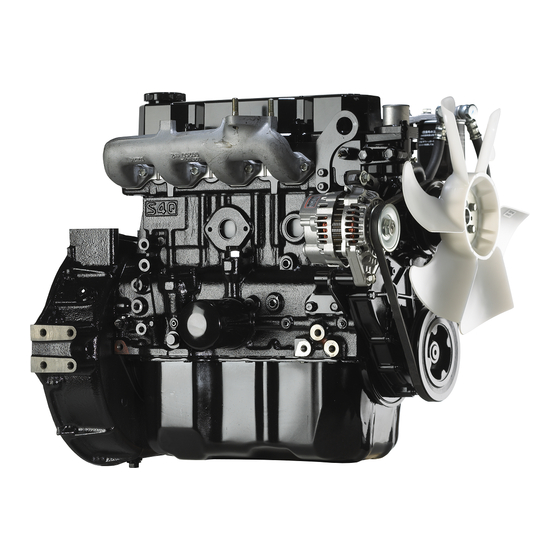
This service manual is written to familiarize you with the maintenance of your S4Q, S4Q2 Diesel Engine. If the
engine is carefully maintained it will deliver a long productive life and efficient performance marked by power and
economy.
Before you attempt to inspect, disassemble, or repair the engine, read this manual carefully to learn more about the
engine and how to care for it properly. All descriptions, illustrations, specifications, and serial numbers in this manual
are effective as of the date printing of this manual.
The information contained in this manual applies to the engine model produced at the time of publication.
It should be noted that specifications and design may change due to improvements made thereafter.
Service Manual
Mitsubishi SQ-Series diesel engines
Version 08/2004
Copyright © 2004 MHI Equipment Europe B.V.
ENGLISH
1 / 174
Service Manual Mitsubishi SQ-Series diesel engines
Version 08/2004
Advertisement
Table of Contents

Related Manuals for Mitsubishi S4Q


Summary of Contents for Mitsubishi S4Q
- Page 1 FOREWORD This service manual is written to familiarize you with the maintenance of your S4Q, S4Q2 Diesel Engine. If the engine is carefully maintained it will deliver a long productive life and efficient performance marked by power and economy. Before you attempt to inspect, disassemble, or repair the engine, read this manual carefully to learn more about the engine and how to care for it properly.
-
Page 2: How To Use This Manual
Indicates the clearance to be obtained between mating parts at reassembly. Repair Limit A part which has reached this limit must be repaired. Service Limit A part which has reached this limit must be replaced. 2 / 174 ENGLISH Service Manual Mitsubishi SQ-Series diesel engines Version 08/2004... -
Page 3: Table Of Contents
15.1 Inspection..........................92 FUEL SYSTEM DESCRIPTION..........................94 FUEL SYSTEM BLEEDING ......................95 DISASSEMBLY ..........................96 FUEL INJECTION TIMING CHECK ....................98 FUEL FILTER (PAPER-ELEMENT CARTRIDGE TYPE) ............. 100 Service Manual Mitsubishi SQ-Series diesel engines ENGLISH 3 / 174 Version 08/2004... - Page 4 33.1 Engine Equipment Condition ....................144 33.2 Tests and Their Purposes....................144 33.3 Other Inspections......................... 144 33.4 Adjustment Engine Output ....................144 TROUBLESHOOTING CAUSES OF ENGINE PROBLEMS AND REMEDIES ..............149 4 / 174 ENGLISH Service Manual Mitsubishi SQ-Series diesel engines Version 08/2004...
- Page 5 36.1 Important Bolts and Nuts ..................... 166 36.2 Standard Bolts ........................167 36.3 Standard Studs ........................167 36.4 Standard Plugs ........................167 THREAD SEALANTS........................168 MAINTENANCE SCHEDULE......................169 SPECIAL TOOLS SPECIAL TOOL LIST........................172 ENGLISH 5 / 174 Service Manual Mitsubishi SQ-Series diesel engines Version 08/2004...
- Page 6 6 / 174 ENGLISH Service Manual Mitsubishi SQ-Series diesel engines Version 08/2004...
- Page 7 GENERAL ENGLISH 7 / 174 Service Manual Mitsubishi SQ-Series diesel engines Version 08/2004...
-
Page 8: General
Stop solenoid Fuel injection pump Speed control lever Fuel feed pump Coolant drain plug Starter V-belt Flywheel Oil pan Flywheel housing Oil drain plug FRONT REAR LEFT SIDE VIEW 8 / 174 ENGLISH Service Manual Mitsubishi SQ-Series diesel engines Version 08/2004... -
Page 9: Engine Serial Number Location
The engine serial number is located on the side of the crankcase. Engine Model and Application Codes e.g. S 4 Q S - Initial of “Sagamihara Machinery Works” 4 - Number-of-cylinders Q - Series code Service Manual Mitsubishi SQ-Series diesel engines ENGLISH 9 / 174 Version 08/2004... -
Page 10: Specifications
Spin-on cartridge of paper-element system Capacity liter [U.S. gal.] Oil pan: 5.5 [1.5], approx. Crankcase: 6.5 [1.7], approx. Starter V-kW 12-2 Electrical Alternator V-A 12-50 system Battery recommended 12V-92Ah 10 / 174 ENGLISH Service Manual Mitsubishi SQ-Series diesel engines Version 08/2004... -
Page 11: General Instructions
GENERAL INSTRUCTIONS ENGLISH 11 / 174 Service Manual Mitsubishi SQ-Series diesel engines Version 08/2004... -
Page 12: Determination Of Overhaul Timing
The most effective way to make a decision is by testing the compression pressure; other factors are to be considered secondarily. 12 / 174 ENGLISH Service Manual Mitsubishi SQ-Series diesel engines Version 08/2004... -
Page 13: Testing The Compression Pressure
) [psi] Assembly Repair Item Standard Limit Compression pressure 2.94 2.55 (30) (26) [427] [370] NOTE Meaure the compression pressure with the engine running at 150 to 200 rpm ENGLISH 13 / 174 Service Manual Mitsubishi SQ-Series diesel engines Version 08/2004... - Page 14 The compression pressure will be slightly higher in a new or overhauled engine due to new piston rings, valve seats, etc. Pressure will drop gradually by the wear of parts. 14 / 174 ENGLISH Service Manual Mitsubishi SQ-Series diesel engines Version 08/2004...
-
Page 15: Tips On Disassembly And Reassembly
Be sure to apply a coat of oil, grease or sealant to parts as specified. Use a torque wrench to tighten parts when specified tightening torques are required. Replace all gaskets and packing. ENGLISH 15 / 174 Service Manual Mitsubishi SQ-Series diesel engines Version 08/2004... -
Page 16: Precautions For Disassembly And Reassembly
Use an O-ring guide to install an O-ring over stepped parts, splines, threads, or key way to prevent damage to the ring. Apply a smear of grease to the O-ring before installation. Figure 4 O-ring guide 16 / 174 ENGLISH Service Manual Mitsubishi SQ-Series diesel engines Version 08/2004... -
Page 17: Bearings
Generally, split pins are to be replaced once disturbed. Insert the pin fully and spread it properly. Drive each spring pin into position to hold it in place after later installation of parts has been completed. ENGLISH 17 / 174 Service Manual Mitsubishi SQ-Series diesel engines Version 08/2004... - Page 18 PRECAUTIONS FOR DISASSEMBLY AND REASSEMBLY GENERAL INSTRUCTIONS 18 / 174 ENGLISH Service Manual Mitsubishi SQ-Series diesel engines Version 08/2004...
-
Page 19: Engine Main Parts
ENGINE MAIN PARTS ENGLISH 19 / 174 Service Manual Mitsubishi SQ-Series diesel engines Version 08/2004... -
Page 20: Cylinder Heads And Valve Mechanism
13. Cylinder head 20. Cylinder head gasket Snap ring 14. Valve cotters 21. Inner valve spring Rocker arm 15. Upper valve retainer 22. Lower valve spring Rocker shaft bracket 20 / 174 ENGLISH Service Manual Mitsubishi SQ-Series diesel engines Version 08/2004... -
Page 21: Removing Cylinder Head
NOTE If the existing valves are to be reused, put a mark on each valve for its location. Figure 11 Removing valves and valve springs ENGLISH 21 / 174 Service Manual Mitsubishi SQ-Series diesel engines Version 08/2004... - Page 22 NOTE Remove the gasket with a scraper, then clean the machined surface with an oilstone and engine oil. Figure 14 Cleaning cylinder head 22 / 174 ENGLISH Service Manual Mitsubishi SQ-Series diesel engines Version 08/2004...
- Page 23 Piston protrusion [0.0051 to 0.0236] Compressed thickness of 1.27 to 1.35 gasket [0.0500 to 0.0531] CAUTION Incorrect piston protrusion affects engine performance and causes valve interference with piston. ENGLISH 23 / 174 Service Manual Mitsubishi SQ-Series diesel engines Version 08/2004...
-
Page 24: Inspection
Check face for pitting or ridging (exhaust Check for pitted or fractured valve). Check stem for scratches or scuff coils. Test force and length. marks. High speed option Figure 16 Inspection points 24 / 174 ENGLISH Service Manual Mitsubishi SQ-Series diesel engines Version 08/2004... - Page 25 [0.7484 to bushing 0.7492] 18.980 to Diameter of 19.000 rocker shaft [0.75] [0.7472 to 0.7480] Clearance 0.010 to between rocker 0.050 0.070 bushing and [0.0004 to [0.0028] shaft 0.0020] ENGLISH 25 / 174 Service Manual Mitsubishi SQ-Series diesel engines Version 08/2004...
- Page 26 Unit: mm [in.] Item Assembly Standard Pushrod runout 0.3 [0.012] or less Figure 20 Measuring valve pushrod runout NOTE Assembly standards refer to dial gage readings. 26 / 174 ENGLISH Service Manual Mitsubishi SQ-Series diesel engines Version 08/2004...
- Page 27 Height to top of valve 15.5 [0.5945 to guide [0.61] 0.6142] NOTE Before measuring the valve guides, clean the guides, removing lacquer or other deposits by running wire brush through them. ENGLISH 27 / 174 Service Manual Mitsubishi SQ-Series diesel engines Version 08/2004...
- Page 28 If the contact is not uniform, or if the valve is defective or if the service limit is exceeded, repair Valve lapper or replace the valve and valve seat. Red lead Figure 25 Inspecting valve face 28 / 174 ENGLISH Service Manual Mitsubishi SQ-Series diesel engines Version 08/2004...
- Page 29 Valve seat When welding the stud to the valve seat, avoid contact of any spatter with the machined surface of the cylinder head. Stud Figure 28 Replacing valve seat ENGLISH 29 / 174 Service Manual Mitsubishi SQ-Series diesel engines Version 08/2004...
- Page 30 Grind the valve as little as possible. If the margin seems to exceed the repair limit as a result of grinding, replace the valve. Figure 31 Refacing valve face 30 / 174 ENGLISH Service Manual Mitsubishi SQ-Series diesel engines Version 08/2004...
- Page 31 Wash off the compound with diesel fuel. Coat the valve face with engine oil, and again lap the valve. Check the valve face for contact. ENGLISH 31 / 174 Service Manual Mitsubishi SQ-Series diesel engines Version 08/2004...
-
Page 32: Reassembly
Stem seal making use of the valve stem as a guide. Valve guide Valve Figure 36 Installing valve stem seal 32 / 174 ENGLISH Service Manual Mitsubishi SQ-Series diesel engines Version 08/2004... - Page 33 Tap the top of the valve with a soft faced hammer several times to make sure the valve spring and valve cotters are properly installed. Figure 39 Testing valve cotter installation ENGLISH 33 / 174 Service Manual Mitsubishi SQ-Series diesel engines Version 08/2004...
- Page 34 Tighten the cylinder head bolts to the specified torque in the sequence shown. Front 118 ± 5 N·m Tightening torque (12.0 ± 0.5 kgf·m) [87 ± 4 lbf·ft] Figure 42 Cylinder head bolt tightening sequence 34 / 174 ENGLISH Service Manual Mitsubishi SQ-Series diesel engines Version 08/2004...
- Page 35 (1.5 ± 0.2 kgf·m) [11 ± 1 lbf·ft] Tightening torque 12 ± 1 N·m Short bolts (1.2 ± 0.1 kgf·m) [9 ± 1 lbf·ft] Figure 44 Installing rocker shaft assembly ENGLISH 35 / 174 Service Manual Mitsubishi SQ-Series diesel engines Version 08/2004...
-
Page 36: Valve Clearance Adjustment
Figure 47 Adjusting valve clearance feeler gage is slightly gripped between the rocker arm and valve cap. After adjusting, tighten the lock nut and recheck the clearance. 36 / 174 ENGLISH Service Manual Mitsubishi SQ-Series diesel engines Version 08/2004... - Page 37 Sequence (cylinder No.) Turning angle 180° 1–3–4–2 CAUTION After adjusting the valve clearance on all cylinders, turn the crankshaft two or three turns and recheck the clearance. ENGLISH 37 / 174 Service Manual Mitsubishi SQ-Series diesel engines Version 08/2004...
-
Page 38: Flywheel
FLYWHEEL ENGINE MAIN PARTS ENGINE MAIN PARTS FLYWHEEL Disassembly Figure 48 Disassembly sequence Flywheel Flywheel housing Gasket Oil seal 38 / 174 ENGLISH Service Manual Mitsubishi SQ-Series diesel engines Version 08/2004... - Page 39 When removing the flywheel, wear heavy gloves to protect your hands. Removing flywheel housing The flywheel housing is doweled. To remove the housing, pull it as straight as possible. Figure 50 Removing flywheel housing Service Manual Mitsubishi SQ-Series diesel engines ENGLISH 39 / 174 Version 08/2004...
-
Page 40: Inspection
Unit: mm [in.] Assembly Repair Item Standard Limit 0.15 [0.0059] 0.50 Flatness of flywheel of less [0.0197] Figure 52 Checking flywheel 40 / 174 ENGLISH Service Manual Mitsubishi SQ-Series diesel engines Version 08/2004... -
Page 41: Reassembly
Tighten the flywheel mounting bolts to the specified torque. 60 ± 6 N·m Tightening torque (6.1 ± 0.6 kgf·m) [44 ± 4 lbf·ft] Figure 55 Installing flywheel housing Service Manual Mitsubishi SQ-Series diesel engines ENGLISH 41 / 174 Version 08/2004... - Page 42 Assembly Item Repair Limit Standard Flywheel 0.50 0.15 [0.059] or less runout [0.0197] Figure 57 Measurement of flywheel runout 42 / 174 ENGLISH Service Manual Mitsubishi SQ-Series diesel engines Version 08/2004...
-
Page 43: Timing Gears, Camshaft And Oil Pan
TIMING GEARS, CAMSHAFT AND OIL Disassembly Figure 58 Disassembly sequence Crankshaft pulley Cover Timing gear case Baffle plate Idler gear Oil pan Oil pump Camshaft Front end plate ENGLISH 43 / 174 Service Manual Mitsubishi SQ-Series diesel engines Version 08/2004... - Page 44 Measuring timing gear backlash [0.0020 to 0.0059] Backlash between 0.25 idler gear and [0.0098] camshaft gear Backlash between 0.04 to 0.16 injection pump drive [0.0016 to 0.0063] gear and idler gear 44 / 174 ENGLISH Service Manual Mitsubishi SQ-Series diesel engines Version 08/2004...
- Page 45 Unit: mm [in.] Assembly Service Item Standard Limit 0.10 to 0.25 0.30 End play of camshaft [0.0039 to 0.0098] [0.0118] Figure 64 Measuring camshaft end play ENGLISH 45 / 174 Service Manual Mitsubishi SQ-Series diesel engines Version 08/2004...
- Page 46 Removing oil pan and gasket Removing oil pump Unscrew the set bolt and remove the oil pump from the crankcase. Oil pump set bolt Figure 67 Removing oil pump 46 / 174 ENGLISH Service Manual Mitsubishi SQ-Series diesel engines Version 08/2004...
- Page 47 10. Removing front plate Unscrew the bolts that hold the front plate to the crankcase. Remove the plate (with the injection pump) from the crankcase. Figure 69 Removing front plate ENGLISH 47 / 174 Service Manual Mitsubishi SQ-Series diesel engines Version 08/2004...
-
Page 48: Inspection
Check for cranks or defective dowel holes. Check oil hole for clogging. Check for wear. Replace Replace Replace Check V-belt groove and oil seal running surface for wear. Figure 70 Inspection points 48 / 174 ENGLISH Service Manual Mitsubishi SQ-Series diesel engines Version 08/2004... -
Page 49: Crankshaft Pulley
After installing the bushing, finish its inside +0.025 +0.0098 diameter to 36 (1.42) H7 ) 0.8 Ra. Figure 73 Replacing idler gear bushing ENGLISH 49 / 174 Service Manual Mitsubishi SQ-Series diesel engines Version 08/2004... - Page 50 Standard Limit +0.1 Inlet 46.916 6.684 6.184 – valve [1.84709] [0.2631] [0.2435] [lobe height] Lobe lift +0.1 Exhaust 45.944 7.344 6.844 – valve [1.80882] [0.2891] [0.2694] [lobe height] 50 / 174 ENGLISH Service Manual Mitsubishi SQ-Series diesel engines Version 08/2004...
- Page 51 2.1280] 54.030 to No. 1 54.050 [2.13] [2.1272 to Inside No. 2 2.1280] diameter of bore for 53.030 to camshaft 53.050 No. 3 [2.09] [2.0878 to 2.0886] ENGLISH 51 / 174 Service Manual Mitsubishi SQ-Series diesel engines Version 08/2004...
- Page 52 Drive the gear onto the camshaft. NOTE Thrust plate Camshaft gear Install the thrust plate before installing the gear to the camshaft. Figure 80 Installing camshaft gear and thrust plate 52 / 174 ENGLISH Service Manual Mitsubishi SQ-Series diesel engines Version 08/2004...
-
Page 53: Reassembly
[9 ± 1 lbf·ft] Make sure the camshaft rotates smoothly. Move the camshaft back and forth in the axial direction to make sure it has correct end play. ENGLISH 53 / 174 Service Manual Mitsubishi SQ-Series diesel engines Version 08/2004... - Page 54 CAUTION To prevent damage to the oil pan, do not place the engine on the floor with the oil pan facing down. Figure 86 Turning crankcase upside down 54 / 174 ENGLISH Service Manual Mitsubishi SQ-Series diesel engines Version 08/2004...
- Page 55 Backlash between idler gear 0.0059] 0.25 and camshaft gear [0.0098] 0.04 to 0.16 Backlash between injection [0.0016 to Figure 89 Checking timing gear backlash pump drive gear and idler gear 0.0063] ENGLISH 55 / 174 Service Manual Mitsubishi SQ-Series diesel engines Version 08/2004...
- Page 56 Tighten the nut with washer to the specified Apply engine oil torque. Figure 92 Installing crankshaft pulley 392 ± 10 N·m Tightening torque (40 ± 1 kgf·m) [289 ± 7 lbf·ft] 56 / 174 ENGLISH Service Manual Mitsubishi SQ-Series diesel engines Version 08/2004...
- Page 57 ENGINE MAIN PARTS CAUTION To ensure safety, make sure the bar and bolt used to prevent the crankshaft from turning have sufficient strength. Figure 93 Crankshaft rotation stopper ENGLISH 57 / 174 Service Manual Mitsubishi SQ-Series diesel engines Version 08/2004...
-
Page 58: Pistons, Connecting Rods, Crankshaft And Crankcase
PISTONS, CONNECTING RODS, CRANKSHAFT AND CRANKCASE ENGINE MAIN PARTS ENGINE MAIN PARTS 10 PISTONS, CONNECTING RODS, CRANKSHAFT AND CRANKCASE 10.1 Disassembly Figure 94 Disassembly sequence 58 / 174 ENGLISH Service Manual Mitsubishi SQ-Series diesel engines Version 08/2004... - Page 59 16. Crankcase NOTE When replacing the crankcase, carefully remove the parts (such as the relief valve, etc.) from the crankcase to reuse them at the time of reassembly. ENGLISH 59 / 174 Service Manual Mitsubishi SQ-Series diesel engines Version 08/2004...
- Page 60 Maximum permissible difference between 10 g Weight rank average weight of all connecting rod [0.35 oz] mark assemblies in one engine Figure 97 Weight rank mark on connecting rod 60 / 174 ENGLISH Service Manual Mitsubishi SQ-Series diesel engines Version 08/2004...
- Page 61 Then remove the piston and connecting rod from the crankcase. Figure 100 Removing piston and connecting rod ENGLISH 61 / 174 Service Manual Mitsubishi SQ-Series diesel engines Version 08/2004...
- Page 62 Unit: mm [in.] Assembly Service Item Standard Limit 0.10 to 0.20 0.30 Figure 104 Measuring end play of crankshaft End play of crankshaft [0.0039 to 0.0080] [0.0118] 62 / 174 ENGLISH Service Manual Mitsubishi SQ-Series diesel engines Version 08/2004...
- Page 63 If bearings scatter during disassembly, they cannot be reinstalled in their original positions. Be sure to arrange the removed bearings in a proper order so that they can be reinstalled in their original positions. ENGLISH 63 / 174 Service Manual Mitsubishi SQ-Series diesel engines Version 08/2004...
-
Page 64: Inspection
Figure 107 Inspection points 64 / 174 ENGLISH Service Manual Mitsubishi SQ-Series diesel engines Version 08/2004... - Page 65 Figure 110 Checking between groove and piston ring between No. 2 0.045 to 0.080 groove and ring [0.0018 to 0.0032] 0.150 piston ring [0.0059] 0.025 to 0.065 ring [0.0010 to 0.0026] ENGLISH 65 / 174 Service Manual Mitsubishi SQ-Series diesel engines Version 08/2004...
- Page 66 If the clearance exceeds the service limit, replace the parts. Measuring points Measuring directions Figure 112 Measuring piston pin and bore 66 / 174 ENGLISH Service Manual Mitsubishi SQ-Series diesel engines Version 08/2004...
- Page 67 After installing the bushing, insert the piston pin into position and make sure it rotates smoothly. End of bushing Figure 114 Installing connecting rod bushing ENGLISH 67 / 174 Service Manual Mitsubishi SQ-Series diesel engines Version 08/2004...
-
Page 68: Connecting Rods
Figure 117 Checking connecting rod with a dial indicator 68 / 174 ENGLISH Service Manual Mitsubishi SQ-Series diesel engines Version 08/2004... - Page 69 0.0018 Undersize 0.50 – 0.030 – 0.0012 57.50 [2.2638 of crankpin [0.0197] – 0.045 – 0.0018 0.75 – 0.030 – 0.0012 57.25 [2.2539 [0.0295] – 0.045 – 0.0018 ENGLISH 69 / 174 Service Manual Mitsubishi SQ-Series diesel engines Version 08/2004...
- Page 70 If the oil clearance still exceeds the repair limit, use 0.25 mm [0.0098 in.], 0.50 mm [0.0197 in.] or 0.75 mm [0.0295 in.] undersize bearings. When using undersize bearings, 70 / 174 ENGLISH Service Manual Mitsubishi SQ-Series diesel engines Version 08/2004...
- Page 71 If the sleeve is badly worn by the oil seal, replace the oil seal sleeve. Oil seal Oil seal running surface Oil seal sleeve Figure 124 Checking oil seal running surface ENGLISH 71 / 174 Service Manual Mitsubishi SQ-Series diesel engines Version 08/2004...
- Page 72 Flywheel housing seal and oil seal sleeve. Oil seal Oil seal running surface Oil seal sleeve Figure 127 Checking oil seal running surface 72 / 174 ENGLISH Service Manual Mitsubishi SQ-Series diesel engines Version 08/2004...
- Page 73 100°C to 150°C [212°F to 302°F]. Install the key to the crankshaft. Install the gear by fitting the key into the keyway in the gear. Figure 130 Installing crankshaft gear ENGLISH 73 / 174 Service Manual Mitsubishi SQ-Series diesel engines Version 08/2004...
- Page 74 (standard value) 0.03 mm [0.0012 in.] C : Honing allowance 0.04 mm [0.0016 in.] or less Finishing dimension = A + B - C Figure 132 Measuring piston diameter 74 / 174 ENGLISH Service Manual Mitsubishi SQ-Series diesel engines Version 08/2004...
- Page 75 10.2.5 Tappets Checking for wear Check the cam contact face of each tappet for wear. Replace badly worn tappets if any. Good Figure 134 Cam contact face of tappet ENGLISH 75 / 174 Service Manual Mitsubishi SQ-Series diesel engines Version 08/2004...
-
Page 76: Reassembly
Only the upper halves of the main bearings Figure 137 Installing main bearings to be installed in the crankcases has an oil groove. 76 / 174 ENGLISH Service Manual Mitsubishi SQ-Series diesel engines Version 08/2004... - Page 77 Tighten the main bearing cap bolts evenly to the specified torque. 83 ± 5 N·m Tightening torque (8.5 ± 0.5 kgf·m) [61 ± 4 lbf·ft] Figure 140 Tightening main bearing cap bolts ENGLISH 77 / 174 Service Manual Mitsubishi SQ-Series diesel engines Version 08/2004...
- Page 78 Apply engine oil to the piston pin and install it in position. Matching mark View A Figure 143 Reassembling piston (1) 78 / 174 ENGLISH Service Manual Mitsubishi SQ-Series diesel engines Version 08/2004...
- Page 79 The oil ring must be installed on the piston with the ring end gap 180° from the coil spring joint. Ring end gap Figure 146 Oil ring end gap and spring joint ENGLISH 79 / 174 Service Manual Mitsubishi SQ-Series diesel engines Version 08/2004...
- Page 80 Make sure the tab on the back of the bearing is in the notch of the connecting rod. Apply engine oil Figure 149 Installing connecting rod bearing 80 / 174 ENGLISH Service Manual Mitsubishi SQ-Series diesel engines Version 08/2004...
- Page 81 Front of engine CAUTION Figure 152 Installing piston assembly (3) Be careful not to cause damage to the crankpin when putting the connecting rod on the crankpin. ENGLISH 81 / 174 Service Manual Mitsubishi SQ-Series diesel engines Version 08/2004...
- Page 82 If the thrust clearance is less than the assembly standard, retighten the cap nuts. 15. Raising crankcase Raise up the crankcase with the oil pan side up. Figure 155 Raising crankcase 82 / 174 ENGLISH Service Manual Mitsubishi SQ-Series diesel engines Version 08/2004...
- Page 83 PISTONS, CONNECTING RODS, ENGINE MAIN PARTS CRANKSHAFT AND CRANKCASE 16. Checking crankshaft rotation Make sure the crankshaft rotates smoothly. Figure 156 Checking crankshaft rotation ENGLISH 83 / 174 Service Manual Mitsubishi SQ-Series diesel engines Version 08/2004...
- Page 84 PISTONS, CONNECTING RODS, CRANKSHAFT AND CRANKCASE ENGINE MAIN PARTS 84 / 174 ENGLISH Service Manual Mitsubishi SQ-Series diesel engines Version 08/2004...
-
Page 85: Inlet And Exhaust System
INLET AND EXHAUST SYSTEM ENGLISH 85 / 174 Service Manual Mitsubishi SQ-Series diesel engines Version 08/2004... -
Page 86: Description
DESCRIPTION INLET AND EXHAUST SYSTEM INLET AND EXHAUST SYSTEM 11 DESCRIPTION Exhaust manifold Inlet manifold 86 / 174 ENGLISH Service Manual Mitsubishi SQ-Series diesel engines Version 08/2004... -
Page 87: Disassembly, Inspection And Reassembly
Check for cracks Replace Put gasket with rounded side toward exhaust manifold when installing it Check for cracks Air inlet elbow Gasket Inlet manifold Gasket Exhaust manifold Gasket ENGLISH 87 / 174 Service Manual Mitsubishi SQ-Series diesel engines Version 08/2004... - Page 88 DISASSEMBLY, INSPECTION AND REASSEMBLY INLET AND EXHAUST SYSTEM 88 / 174 ENGLISH Service Manual Mitsubishi SQ-Series diesel engines Version 08/2004...
-
Page 89: Cooling System
COOLING SYSTEM ENGLISH 89 / 174 Service Manual Mitsubishi SQ-Series diesel engines Version 08/2004... -
Page 90: Description
DESCRIPTION COOLING SYSTEM COOLING SYSTEM 13 DESCRIPTION Radiator Thermostat Bypass pipe Water pump 90 / 174 ENGLISH Service Manual Mitsubishi SQ-Series diesel engines Version 08/2004... -
Page 91: Water Pump, Fan
Check for coolant leakage, rough rotation or cracks Check for wear, fraying or separated piles Figure 157 Disassembly sequence Spacer Pulley V-belt Water Pump assembly Gasket Plate Gasket Service Manual Mitsubishi SQ-Series diesel engines ENGLISH 91 / 174 Version 08/2004... -
Page 92: Thermostat
90°C [194°F] exceeds 8 mm [0.3 in.] CAUTION Stir up the water with a stick to keep the temperature uniform. Install the thermostat with its air vent hole 92 / 174 ENGLISH Service Manual Mitsubishi SQ-Series diesel engines Version 08/2004... -
Page 93: Fuel System
FUEL SYSTEM ENGLISH 93 / 174 Service Manual Mitsubishi SQ-Series diesel engines Version 08/2004... -
Page 94: Description
DESCRIPTION FUEL SYSTEM FUEL SYSTEM 16 DESCRIPTION Fuel filter Air vent plug Fuel injection nozzle Return pipe Air vent plug Fuel feed pump Fuel injection pump 94 / 174 ENGLISH Service Manual Mitsubishi SQ-Series diesel engines Version 08/2004... -
Page 95: Fuel System Bleeding
If the vent plug is tightened before the bleeding pump plunger is locked, fuel pressure acts on the feed pump, making it difficult to restore the plunger. Clean up fuel spillage. Bleeding button Service Manual Mitsubishi SQ-Series diesel engines ENGLISH 95 / 174 Version 08/2004... -
Page 96: Disassembly
Removing fuel injection pump Check the alignment of the mark on the fuel injection pump with the mark on the flange plate. Figure 161 Removing fuel injection pump (1) 96 / 174 ENGLISH Service Manual Mitsubishi SQ-Series diesel engines Version 08/2004... - Page 97 To remove the fuel injection pump drive Figure 162 Removing fuel injection pump (2) gear, loosen its nut with the pump on the engine. Service Manual Mitsubishi SQ-Series diesel engines ENGLISH 97 / 174 Version 08/2004...
-
Page 98: Fuel Injection Timing Check
Make sure the timing mark on the crankshaft pulley is aligned with the pointer. Figure 165 Checking injection timing (2) 98 / 174 ENGLISH Service Manual Mitsubishi SQ-Series diesel engines Version 08/2004... - Page 99 Figure 166 Adjusting injection timing (1) One graduation of the scale on the injection pump coupling changes the timing by 6° in terms of crank angle. Figure 167 Adjusting injection timing (2) Service Manual Mitsubishi SQ-Series diesel engines ENGLISH 99 / 174 Version 08/2004...
-
Page 100: Fuel Filter (Paper-Element Cartridge Type)
20.1 Disassembly and Inspection Air vent plug Cracks, damages threads Apply engine oil to packing at installation Clogged, cracked. Replace every 500 service hours. Figure 168 Disassembly sequence Element assembly Bracket 100 / 174 ENGLISH Service Manual Mitsubishi SQ-Series diesel engines Version 08/2004... -
Page 101: Fuel Injection Nozzles
Check for defect Check for wear Check for carbon on tip or in orifice Figure 169 Disassembly sequence Retaining nut Nozzle tip assembly Piece Spring Washer Nozzle body Service Manual Mitsubishi SQ-Series diesel engines ENGLISH 101 / 174 Version 08/2004... -
Page 102: Testing
If the injection pressure is not correct, make an adjustment of the nozzle by adding or removing the shims inside the nozzle holder. Figure 171 Removing nozzle tip 102 / 174 ENGLISH Service Manual Mitsubishi SQ-Series diesel engines Version 08/2004... - Page 103 When installing a new nozzle tip, remove resin film from the tip and slide the needle valve in the body in clean diesel fuel to wash off inhibitor completely. Service Manual Mitsubishi SQ-Series diesel engines ENGLISH 103 / 174 Version 08/2004...
-
Page 104: Reassembly
(3.77 ± 0.25 kgf·m) [27 ± 1.8 lbf·ft] Tightening torque for fuel injection nozzle: 59 ± 10 N·m (6.0 ± 1 kgf·m) [44 ± 7 lbf·ft] Figure 174 Ressembly sequence 104 / 174 ENGLISH Service Manual Mitsubishi SQ-Series diesel engines Version 08/2004... -
Page 105: Lubrication System
LUBRICATION SYSTEM ENGLISH 105 / 174 Service Manual Mitsubishi SQ-Series diesel engines Version 08/2004... -
Page 106: Description
Valve mechanism Valve push rod Tappet Valve Pressure relief Piston valve Camshaft Main gallery Timing gear Crankshaft Oil pump Oil filter (with built-in Oil strainer bypass valve) Drain plug 106 / 174 ENGLISH Service Manual Mitsubishi SQ-Series diesel engines Version 08/2004... -
Page 107: Oil Pump
Item Standard Limit Figure 176 Checking clearance between outer rotor and inner rotor Clearance between outer 0.13 to 0.15 0.20 rotor and inner rotor [0.0051 to 0.0059] [0.0079] Service Manual Mitsubishi SQ-Series diesel engines ENGLISH 107 / 174 Version 08/2004... -
Page 108: Reassembly
Put the outer rotor in the case. Make sure the mark on the case is in alignment with the mark on the cover and tighten the bolts that hold the cover. Figure 179 Marks on cover and case 108 / 174 ENGLISH Service Manual Mitsubishi SQ-Series diesel engines Version 08/2004... -
Page 109: Oil Filter
LUBRICATION SYSTEM OIL FILTER LUBRICATION SYSTEM 24 OIL FILTER 24.1 Inspection Apply engine oil to O-ring at installation Replace every 250 service hours Oil filter Service Manual Mitsubishi SQ-Series diesel engines ENGLISH 109 / 174 Version 08/2004... -
Page 110: Pressure Relief Valve
Figure 180 Pressure relief valve near the oil filter. Unit: kPa (kgf/cm ) [psi] Item Assembly Standard 343 ± 49 Valve opening pressure (3.5 ± 0.5) [50 ± 7] 110 / 174 ENGLISH Service Manual Mitsubishi SQ-Series diesel engines Version 08/2004... - Page 111 ELECTRICAL SYSTEM ENGLISH 111 / 174 Service Manual Mitsubishi SQ-Series diesel engines Version 08/2004...
-
Page 112: Electrical System General
GENERAL ELECTRICAL SYSTEM ELECTRICAL SYSTEM 26 GENERAL 26.1 Wiring diagrams < ETS type stop solenoid > 112 / 174 ENGLISH Service Manual Mitsubishi SQ-Series diesel engines Version 08/2004... - Page 113 ELECTRICAL SYSTEM GENERAL < ETR type stop solenoid > Service Manual Mitsubishi SQ-Series diesel engines ENGLISH 113 / 174 Version 08/2004...
-
Page 114: Starter
Standard Item value Figure 182 No-load test Starter model M008T70371 Nominal output V-kW 12-2.0 Terminal voltage No-load Current 130 or lower characteristics Rotation speed rpm 3600 or higher 114 / 174 ENGLISH Service Manual Mitsubishi SQ-Series diesel engines Version 08/2004... - Page 115 The pinion should extend when the switch is turned on. CAUTION — Do not supply electricity for more than 10 continuous Battery seconds. 24V (option) Disconnect connector Figure 183 Suction test Service Manual Mitsubishi SQ-Series diesel engines ENGLISH 115 / 174 Version 08/2004...
-
Page 116: Removal
Be sure to disconnect the negative (-) cable first. Disconnect the wires from the starter. Remove the two starter mounting nuts, and dismount the starter. Wires Figure 186 Removal of starter 116 / 174 ENGLISH Service Manual Mitsubishi SQ-Series diesel engines Version 08/2004... -
Page 117: Disassembly
CAUTION Before disassembling or replacing the following parts, remove the pinion. Remove the pinion before disassembling: Front bracket, or bracket bearing and oil seal Reduction gears Overrunning clutch Service Manual Mitsubishi SQ-Series diesel engines ENGLISH 117 / 174 Version 08/2004... -
Page 118: Inspection
Replace the armature if shorted. Testing for grounded circuits If there is any continuity between the commutator and shaft (or core), the armature is grounded and should be replaced. 118 / 174 ENGLISH Service Manual Mitsubishi SQ-Series diesel engines Version 08/2004... - Page 119 Testing for open circuits If there is no continuity between the lead wire and positive (+) brush, the field coil is open and the yoke assembly should be replaced. Service Manual Mitsubishi SQ-Series diesel engines ENGLISH 119 / 174 Version 08/2004...
- Page 120 [6.6 to 8.8] [4.4] Testing brush holders insulation If there is any continuity between the positive (+) brush holder and negative (–) holder plate, replace the brush holder assembly. 120 / 174 ENGLISH Service Manual Mitsubishi SQ-Series diesel engines Version 08/2004...
-
Page 121: Reassembly
18 → 17 → 16 → 12 → 13 → 14 → 15 → 1 → 10 → 11 → 9 → 8 → 5 → 6 → 7 → 4 → 3 → 2 Service Manual Mitsubishi SQ-Series diesel engines ENGLISH... -
Page 122: Inspection And Testing After Reassembly
Use wires as thick as possible and tighten each terminal securely. Voltage, Current, Speed, Starter 130 or less 4000 or less No-Load characteristic 80 or less 3000 or (Option) more 122 / 174 ENGLISH Service Manual Mitsubishi SQ-Series diesel engines Version 08/2004... - Page 123 If there is continuity between B and M terminals, replace the switch. Checking contactors for poor contact action Check for voltage drop. If voltage drop is M terminal excessive, the contactors are defective. Service Manual Mitsubishi SQ-Series diesel engines ENGLISH 123 / 174 Version 08/2004...
-
Page 124: Alternator
Do not short or ground terminal L. (unit with integrated IC regulator) When using a steam cleaner, do not allow steam to directly contact the alternator. 124 / 174 ENGLISH Service Manual Mitsubishi SQ-Series diesel engines Version 08/2004... - Page 125 If the measured value conforms to the standard value, the alternator is normal. Figure 188 Wiring diagram for output test (unit with integrated IC regulator) Service Manual Mitsubishi SQ-Series diesel engines ENGLISH 125 / 174 Version 08/2004...
-
Page 126: Removal
Unscrew the alternator brace bolt and support bolt, and push the alternator toward the engine, then remove the fan belt. Dismount the alternator. Support bolt Figure 189 Removal of alternator 126 / 174 ENGLISH Service Manual Mitsubishi SQ-Series diesel engines Version 08/2004... -
Page 127: Disassembly
28.3 Disassembly Not provided in 24V-35A (A3TN5776) Disassembly sequence Nut and washer Pulley and spacer Front bracket assembly Rotor assembly Stator Rear bracket Regulator assembly Rectifier assembly Nut set Service Manual Mitsubishi SQ-Series diesel engines ENGLISH 127 / 174 Version 08/2004... - Page 128 Soldered section Figure 192 Removal of stator core Unscrew the rectifier mounting screws, and dismount the rectifier. 128 / 174 ENGLISH Service Manual Mitsubishi SQ-Series diesel engines Version 08/2004...
-
Page 129: Inspection
0 in both measurements, there is a short circuit. Diode lead If there is an open or short circuit, the diode is (+) heat sink faulty and the rectifier must be replaced. Figure 194 Inspecting diodes Service Manual Mitsubishi SQ-Series diesel engines ENGLISH 129 / 174 Version 08/2004... - Page 130 Check the continuity between the stator core and each lead wire. If there is no electric conduction, there is an open circuit: replace the stator core. Figure 197 Stator core continuity test 130 / 174 ENGLISH Service Manual Mitsubishi SQ-Series diesel engines Version 08/2004...
- Page 131 (A7TA80AA) (A3TN5776) Figure 199 Inspecting brush Disconnect the brush lead wires at the soldered sections to remove the brushes and springs. Soldered sections Figure 200 Replacement of brushes Service Manual Mitsubishi SQ-Series diesel engines ENGLISH 131 / 174 Version 08/2004...
-
Page 132: Assembly
Using the bar as leverage, move the alternator and adjust the belt tension. While keeping the alternator at that position, tighten the bolt that secures the alternator to the adjusting plate. Figure 203 Installation of alternator 132 / 174 ENGLISH Service Manual Mitsubishi SQ-Series diesel engines Version 08/2004... - Page 133 (10 kgf) [22 lbf]) Bolt pulley When the belt tension is properly adjusted, tighten all the bolts that secure the alternator in place. Figure 204 Inspection of belt tension Service Manual Mitsubishi SQ-Series diesel engines ENGLISH 133 / 174 Version 08/2004...
-
Page 134: Etr Type Stop Solenoid
The engine then stops. This system is a safety device designed to stop the engine whenever the wiring is open or when the starter switch is turned "OFF". 134 / 174 ENGLISH Service Manual Mitsubishi SQ-Series diesel engines Version 08/2004... -
Page 135: Solenoid Specification
1.1 A 0.6 A 0.217 0.817 common ground black Notice that the housing is ungrounded. Replace the complete solenoid if not within the above mentioned specification. Service Manual Mitsubishi SQ-Series diesel engines ENGLISH 135 / 174 Version 08/2004... -
Page 136: Inspection
Wrong adjustment will cause that the engine can not run or can not be stopped. It is also possible that the engine can not reach its maximum output. 136 / 174 ENGLISH Service Manual Mitsubishi SQ-Series diesel engines Version 08/2004... -
Page 137: Glow Plugs
Install the connection plate to the glow plug, and tighten the retaining nut to the specified torque. 1.3 ± 0.2 N·m Tightening torque (0.13 ± 0.02 kgf·m) [0.96 ± 0.14 lbf·ft] Service Manual Mitsubishi SQ-Series diesel engines ENGLISH 137 / 174 Version 08/2004... - Page 138 GLOW PLUGS ELECTRICAL SYSTEM 138 / 174 ENGLISH Service Manual Mitsubishi SQ-Series diesel engines Version 08/2004...
-
Page 139: Testing And Adjusting
TESTING AND ADJUSTING ENGLISH 139 / 174 Service Manual Mitsubishi SQ-Series diesel engines Version 08/2004... -
Page 140: Bench Test
Check for leakage of oil, coolant, fuel. Knocking should die away as the coolant temperature increases. No other defective noise should be heard. Check for exhaust color and abnormal odors. 140 / 174 ENGLISH Service Manual Mitsubishi SQ-Series diesel engines Version 08/2004... -
Page 141: Bench Testing (Dynamometer) Conditions
Time (min.) 1000 No-load 1500 Ratted (varies according to specifications) 100% 31.4 Inspection and Adjustment after Bench Testing Adjusting valve clearance Adjusting injection timing Re-tightening external bolts and nuts Service Manual Mitsubishi SQ-Series diesel engines ENGLISH 141 / 174 Version 08/2004... -
Page 142: Idling Speed And Maximum Speed Setting Inspection And Adjustment
These settings are to be inspected and adjusted at Mitsubishi service shops only. After adjusting the governor be sure to seal the stopper. The stoppers are specified to be sealed. - Page 143 With the speed control lever held in that position, adjust and set the governor set bolt (maximum rotation speed set bolt) to the specified rotation speed. Figure 211 Governor setting ENGLISH 143 / 174 Service Manual Mitsubishi SQ-Series diesel engines Version 08/2004...
-
Page 144: Performance Test
Make adjustment, as needed. 33.4 Adjustment Engine Output Diesel engine output is affected by atmospheric pressure, temperature, and humidity. Therefore, the engine output should be set for standard atmospheric conditions. 144 / 174 ENGLISH Service Manual Mitsubishi SQ-Series diesel engines Version 08/2004... - Page 145 Stroke volume Engine revolution rpm z = 120000 (4-cycle engine) r: Ratio of pressure at turbocharger or air cooler to atmospheric pressure (r = 1 for natural aspiration engine) Service Manual Mitsubishi SQ-Series diesel engines ENGLISH 145 / 174 Version 08/2004...
- Page 146 0.9 ≤ c ≤ 1.1. α If this range is exceeded, indicate the corrected value and record the test conditions on the test record sheet. 146 / 174 ENGLISH Service Manual Mitsubishi SQ-Series diesel engines Version 08/2004...
- Page 147 TROUBLESHOOTING ENGLISH 147 / 174 Service Manual Mitsubishi SQ-Series diesel engines Version 08/2004...
- Page 148 148 / 174 ENGLISH Service Manual Mitsubishi SQ-Series diesel engines Version 08/2004...
-
Page 149: Troubleshooting
CAUSES OF ENGINE PROBLEMS AND TROUBLESHOOTING REMEDIES TROUBLESHOOTING 34 CAUSES OF ENGINE PROBLEMS AND REMEDIES ENGLISH 149 / 174 Service Manual Mitsubishi SQ-Series diesel engines Version 08/2004... - Page 150 Oil viscosity is too low Oil pressure does not rise Oil leaks ⊗ ⊗ ⊗ Excessive pumping up of oil Clogged oil filter Oil pressure switch or lamp defective 150 / 174 ENGLISH Service Manual Mitsubishi SQ-Series diesel engines Version 08/2004...
- Page 151 Use oil of proper viscosity. ⊗ • Tighten bolts and nuts. Replace ⊗ packing(s) if necessary. ⊗ • ⊗ Replace filter element and oil. ⊗ ⊗ Replace filter element and oil. ENGLISH 151 / 174 Service Manual Mitsubishi SQ-Series diesel engines Version 08/2004...
- Page 152 ⊗ Open circuit in glow plug or ⊗ ⊗ pilot lamp ⊗ ⊗ Short circuit in glow plug Alternator malfunction Relay defective ⊗ ⊗ ⊗ ⊗ Wiring defective 152 / 174 ENGLISH Service Manual Mitsubishi SQ-Series diesel engines Version 08/2004...
- Page 153 Replace part(s). Replace copper packing(s). Replace glow plug(s), if necessary. ⊗ Replace alternator if necessary. ⊗ ⊗ ⊗ Adjust or replace. ⊗ ⊗ Connect wires properly. ENGLISH 153 / 174 Service Manual Mitsubishi SQ-Series diesel engines Version 08/2004...
- Page 154 ⊗ ⊗ ⊗ ⊗ ⊗ ⊗ Damaged valve spring(s) Excessive valve clearance ⊗ ⊗ ⊗ ⊗ ⊗ ⊗ ⊗ ⊗ Foreign item in cylinder(s) Excessive gear backlash ⊗ 154 / 174 ENGLISH Service Manual Mitsubishi SQ-Series diesel engines Version 08/2004...
- Page 155 Reinstall timing gears or adjust valve sinkage. ⊗ ⊗ Replace part(s). Adjust valve clearance to 0.25 ⊗ ⊗ mm [0.0098 in.]. Repair. Repair gear(s) or idler gear bushing. ENGLISH 155 / 174 Service Manual Mitsubishi SQ-Series diesel engines Version 08/2004...
-
Page 156: English Service Manual Mitsubishi Sq-Series Diesel Engines
Faulty mounting angle of injection pump Tilt injection pump toward outside of engine and retarded adjust timing. Timing gears incorrectly installed Correct timing gear engagement. Worn fuel injection pump bearing Replace parts. 156 / 174 ENGLISH Service Manual Mitsubishi SQ-Series diesel engines Version 08/2004... - Page 157 Rust or water scale accumulation inside radiator Clean. Dust accumulation on radiator Clean. Fan belt slipping Adjust belt tension. Thermostat defective (stuck closed) Replace parts. ENGLISH 157 / 174 Service Manual Mitsubishi SQ-Series diesel engines Version 08/2004...
- Page 158 Seizing of cylinder(s), piston(s) or piston ring(s) Disassemble and repair. Replace parts. Seizing of main or connecting rod bearing(s) Disassemble and repair. Replace parts. Seizing of idler gear bushing Disassemble and repair. Replace parts. 158 / 174 ENGLISH Service Manual Mitsubishi SQ-Series diesel engines Version 08/2004...
-
Page 159: Maintenance Standards
MAINTENANCE STANDARDS ENGLISH 159 / 174 Service Manual Mitsubishi SQ-Series diesel engines Version 08/2004... -
Page 160: Maintenance Standards Table
0.015 [0.0006] or Cylindricity less +0.019 Inside diameter +0.0008 [2.72] [2.72 With main bearing cap 0.02 [0.0008] or Out-of-round installed (bolts tightened). less 0.05 [0.0020] or Concentricity less 160 / 174 ENGLISH Service Manual Mitsubishi SQ-Series diesel engines Version 08/2004... - Page 161 [0.0512] 1.18 1.04 to 1.32 Width [0.05] [0.0409 to 0.0520] [0.0630] Valve Up to 1.20 1.70 Valve margin Valve margin [0.0472] by Valve seat sinkage [0.0669] refacing angle Service Manual Mitsubishi SQ-Series diesel engines ENGLISH 161 / 174 Version 08/2004...
- Page 162 0.01 [0.0004] or 0.03 less [0.0012] Taper of journal and crankpin Fillet radius of journal ±0.2 [±0.008] and crankpin [0.12] (0.10 to 0.20) (0.30) End play ([0.0039 to 0.0080]) ([0.0118]) 162 / 174 ENGLISH Service Manual Mitsubishi SQ-Series diesel engines Version 08/2004...
- Page 163 ([0.0059 to 0.0138]) ([0.020]) (End play) Weight difference in one 10 g [0.35 oz] or engine less 0.15 [0.0059] or Flatness less 0.50 [0.0197] 0.15 [0.0059] or Face runout less Service Manual Mitsubishi SQ-Series diesel engines ENGLISH 163 / 174 Version 08/2004...
- Page 164 [psi] [50] [50 ± 7] Temp. at which valve 76.5 ± 1.5°C starts opening [170 ± 2.7°F] Temp. at which valve 90°C [194°F] lifts more than 8 [0.3] 164 / 174 ENGLISH Service Manual Mitsubishi SQ-Series diesel engines Version 08/2004...
- Page 165 16 volts or less, with pinion held at 2 mm [0.08 in.] position from cranking position 80 or less 3000 or more [0.276] 18.5 5 [0.197] Brush length [0.728] Option (A7TA80AA) (A3TN5776) Resistance between slip Ω At 20°C [68°F] ring Service Manual Mitsubishi SQ-Series diesel engines ENGLISH 165 / 174 Version 08/2004...
-
Page 166: Tightening Torques
M16 x 1.5 19 [0.75] 23 ± 2 2.3 ± 0.2 17 ± 1 Drain plug M16 x 1.5 24 [0.94] 44 ± 5 4.5 ± 0.5 33 ± 4 166 / 174 ENGLISH Service Manual Mitsubishi SQ-Series diesel engines Version 08/2004... -
Page 167: Standard Bolts
25 ± 5 2.5 ± 0.5 18 ± 4 39 ± 5 4.0 ± 0.5 29 ± 4 PT 3/8 64 ± 10 6.5 ± 1 47 ± 7 Service Manual Mitsubishi SQ-Series diesel engines ENGLISH 167 / 174 Version 08/2004... -
Page 168: Thread Sealants
Starter mounting stud Rear plate Three Bond 1344 Apply to stud and tighten. Injection pump mounting stud Flange plate Three Bond 1344 Apply to stud and tighten. 168 / 174 ENGLISH Service Manual Mitsubishi SQ-Series diesel engines Version 08/2004... -
Page 169: Maintenance Schedule
Every 50 service hours and Every 10 service hours. Check, clean, wash or adjust. ⊗ • Change. Rely on Mitsubishi dealer if necessary. Items to be serviced after initial 50 hours of operation of a new, reconditioned or long-stored engine. Interval Group... - Page 170 Clean element (paper-element type) Change • element Check Check specific electrolyte level ⊗ Battery gravity from and specific time to time gravity Alternator Check ⊗ Starter Check ⊗ 170 / 174 ENGLISH Service Manual Mitsubishi SQ-Series diesel engines Version 08/2004...
-
Page 171: Special Tools
SPECIAL TOOLS ENGLISH 171 / 174 Service Manual Mitsubishi SQ-Series diesel engines Version 08/2004... -
Page 172: Special Tool List
Exhaust 30691-02800 Idler gear bushing 30691-51900 Idler gear bushing removal/ installer installation Idler gear shaft puller MH061077 Idler gear shaft removal Piston ring pliers 31391-12900 Piston ring removal/installation 172 / 174 ENGLISH Service Manual Mitsubishi SQ-Series diesel engines Version 08/2004... - Page 173 Compression gage 33391-02100 Compression pressure testing Turning handle 30691-21800 Engine turning Socket 34491-00300 Camshaft thrust plate and rocker shaft bracket installation Stem seal installer 32A91-00200 Stem seal installation Service Manual Mitsubishi SQ-Series diesel engines ENGLISH 173 / 174 Version 08/2004...
- Page 174 BLANK PAGE 174 / 174 ENGLISH Service Manual Mitsubishi SQ-Series diesel engines Version 08/2004...