Graco ULTRA 500 Instructions-Parts List Manual
Hide thumbs
Also See for ULTRA 500:
- Instructions-parts list manual (38 pages) ,
- Instructions-parts list manual (37 pages) ,
- Instructions-parts list manual (45 pages)
Table of Contents
Advertisement
INSTRUCTIONS–PARTS LIST
220/240 VAC
ULTRA 500
AIRLESS PAINT SPRAYER
195 bar (2750 psi) Maximum Working Pressure
Model 231–079, Series D
Complete sprayer on Upright cart with hose,
gun, RAC IV
DripLess
and SwitchTip
GRACO INC. P.O. BOX 1441 MINNEAPOLIS, MN 55440–1441
This manual contains important
warnings and information.
READ AND RETAIN FOR REFERENCE
Tip Guard
COPYRIGHT 1995, GRACO INC.
307–889
Supercedes Rev J, never released,
Rev K
and Rev H
Advertisement
Table of Contents

Related Manuals for Graco ULTRA 500


Summary of Contents for Graco ULTRA 500
- Page 1 AIRLESS PAINT SPRAYER 195 bar (2750 psi) Maximum Working Pressure Model 231–079, Series D Complete sprayer on Upright cart with hose, gun, RAC IV DripLess Tip Guard and SwitchTip GRACO INC. P.O. BOX 1441 MINNEAPOLIS, MN 55440–1441 COPYRIGHT 1995, GRACO INC.
-
Page 2: Table Of Contents
....... . . The Graco Warranty and Disclaimers ... . -
Page 3: Warnings
This equipment is for professional use only. Read all instruction manuals, tags, and labels before operating the equipment. Use the equipment only for its intended purpose. If you are not sure, call Graco Technical Assis- tance at 1–800–543–0339. Do not alter or modify this equipment. - Page 4 WARNING WARNING INJECTION HAZARD Spray from the gun, leaks or ruptured components can inject fluid into your body and cause ex- tremely serious injury, including the need for amputation. Fluid splashed in the eyes or on the skin can also cause serious injury. Fluid injected into the skin is a serious injury.
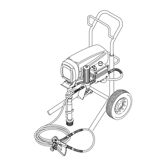
- Page 5 Major Compo- nents Fig. 1 Motor DC motor, 220/240 Vac, 50 Hz, 7A, 1 phase Pressure Adjusting Knob Controls fluid outlet pressure ON/OFF Switch Power switch that controls 220/240 Vac main power to sprayer Drive Assembly Transfers power from DC motor to the displacement pump Fluid Filter Final filter of fluid between source and spray gun Displacement Pump...
- Page 6 Setup NOTE: See Fig. 2 while doing the setup. WARNING 1. Fill the packing nut/wet-cup 1/3 full with Graco To reduce the risk of serious injury from static Throat Seal Liquid (TSL), supplied. sparking, injection, or over pressurization and rupture of the hose or gun, all hoses must be electri- 2.
- Page 7 Setup PRESSURE ADJUSTING KNOB ON/OFF SWITCH PRESSURE PACKING NUT/ WET–CUP DRAIN VALVE FILL 1/3 FULL WITH TSL 1/4 npsm(m) FLUID OUTLET NIPPLE DO NOT INSTALL ANY SHUTOFF DEVICE HERE Fig. 2...
- Page 8 Startup Use this procedure each time you start the sprayer to c. Release the trigger. Engage the gun safety latch. help ensure the sprayer is ready to operate and that you 5. Check all fluid connections for leaks. Relieve start it safely. the fluid pressure before tightening connections.
-
Page 9: Cleaning A Clogged Tip
Startup Cleaning a Clogged Tip 4. Return the handle to the original position, disengage the gun safety latch, and resume spraying. WARNING 5. If the tip is still clogged, engage the gun safety latch, shut off and unplug the sprayer, and open the pres- FLUID INJECTION HAZARD sure drain valve to relieve pressure. -
Page 10: Shutdown And Care
Shutdown and Care 6. Coil the hose and hang it on the hose rack when WARNING storing it, even for overnight, to help protect the hose from kinking, abrasion, coupling damage, etc. FLUID INJECTION HAZARD To reduce the risk of serious injury, follow the illustrated Pressure Relief Procedure warning on page 12 when- ever you are instructed to relieve pressure. -
Page 11: Flushing
Flushing NOTE: Several flushes are often required to thoroughly clean the system and prepare it for the next fluid to be sprayed, or to store the sprayer. Use this chart to determine the required flushing order for the fluid you are using, and then follow the procedure below for flushing. -
Page 12: Troubleshooting
Troubleshooting Pressure Relief Procedure Disengage the gun safety latch. Hold a metal part of the gun firmly to the side of a grounded metal pail, and trig- To reduce the risk of serious bodily injury, including fluid in- ger the gun to relieve pressure. jection, splashing fluid or solvent in the eyes or on the skin, or injury from moving parts or electric shock, always follow Engage the gun safety latch. - Page 13 MOTOR WON’T OPERATE (Continued) TYPE OF PROBLEM WHAT TO CHECK WHAT TO DO If check is OK, go to next check When check is not OK refer to this column Follow Pressure Relief Proce- 1 . Check leads from motor to be sure they are 1.
-
Page 14: Low Output
LOW OUTPUT TYPE OF PROBLEM WHAT TO CHECK WHAT TO DO If check is OK, go to next check When check is not OK refer to this column Low Output 1. Follow Pressure Relief Procedure Warn- 1. Check for worn spray tip. ing then replace tip. -
Page 15: Excessive Pressure Fluctuations
NO OUTPUT TYPE OF PROBLEM WHAT TO CHECK WHAT TO DO If check is OK, go to next check When check is not OK refer to this column Motor runs and pump strokes 1. Check paint supply. 1. Refill and reprime pump. 2. -
Page 16: Electrical Short
MOTOR IS HOT AND RUNS INTERMITTENTLY TYPE OF PROBLEM WHAT TO CHECK WHAT TO DO If check is OK, go to next check When check is not OK refer to this column Motor is hot and runs intermit- 1. Determine if sprayer was operated at high 1. - Page 17 For checking armature, motor winding and brush electri- Armature, Brushes, and Motor Wiring Open cal continuity. Circuit Test (Continuity) Relieve pressure. Connect the two black motor leads to- Setup gether with a test lead. T urn the motor fan by hand at Relieve pressure.
-
Page 18: General Repair Information
General Repair Information WARNING CAUTION To reduce the risk of a pressure control malfunction: ELECTRIC SHOCK HAZARD To reduce the risk of serious injury, in- Always use needle nose pliers to disconnect a cluding electric shock, DO NOT touch wire. Never pull on the wire, pull on the connec- any moving parts or electrical parts with tor. -
Page 19: Motor Brush Replacement
Motor Brush Replacement NOTE: Replace the brushes when they have worn to 5. Inspect the commutator for excessive pitting, burn- less than 12 mm (1/2 in). Note that the brushes ing or gouging. A black color on the commutator is wear dif ferently on each side of the motor , so normal. -
Page 20: Power Supply Cord Replacement
11. Test the brushes. CAUTION a. Remove the pump connecting rod pin. Do not run the sprayer dry for more than 30 sec- onds while checking the brushes to avoid damag- b. With the sprayer OFF, turn the pressure con- ing the displacement pump packings. -
Page 21: On/Off Switch Replacement
On/Off Switch Replacement (Fig. 16) 8. Powder the inside of the rubber boot (309) with WARNING talcum powder, then shake the excess out of the boot. FLUID INJECTION HAZARD To reduce the risk of serious injury, 9. Install the nut and rubber boot and tighten. follow the illustrated Pressure Relief Procedure warning on page 12 when- 10. -
Page 22: Pressure Control Replacement
Pressure Control Replacement 3. Remove the four mounting screws and washers WARNING (302, 303, 304) from the pressure control board/ cover (301). See Fig. 18. FLUID INJECTION HAZARD To reduce the risk of serious injury, 4. Carefully remove the pressure control board/cover follow the illustrated Pressure Relief (301) so as not to stress the cables. -
Page 23: Filter Board Replacement
Pressure Control Replacement 12. Reassemble in the reverse order; attach ground WARNING wire (C), power leads (L1 and L2), the red leads to the TS terminals on the circuit board (B1), the M+ Do not attempt to adjust or calibrate the pressure and M–... - Page 24 Drive Housing, Connecting Rod, and Crankshaft Replacement (Fig. 20) 5. Remove the screws (12), spacers (15), screws WARNING (16) and the motor shield (1). FLUID INJECTION HAZARD 6. Remove the two screws (58) and lockwashers (7) To reduce the risk of serious injury, holding the motor to the drive housing.
-
Page 25: Drive Housing, Connecting Rod, And Crankshaft Replacement
Drive Housing, Connecting Rod, and Crankshaft Replacement Fill cavity with SAE non-detergent motor oil Fig. 20... - Page 26 Motor Replacement (Fig. 21 and 22) 12. Remove the two screws (58) and lockwashers (7) WARNING from the motor (2). FLUID INJECTION HAZARD 13. Tap the drive housing (6) with a plastic mallet to To reduce the risk of serious injury, loosen it from the front of the motor (2), and then follow the illustrated Pressure Relief pull the drive housing straight off.
-
Page 27: Motor Replacement
Motor Replacement DETAIL Shows position of conduit seal (31) in conduit connector (318) M– – MOTOR POWER CORD Fig. 21 LIBERALLY APPLY GREASE Fig. 22... - Page 28 Displacement Pump Repair (Fig. 23 – 32) Disassembling the pump. WARNING 1. Unscrew the intake valve (223) and remove all FLUID INJECTION HAZARD parts. See Fig. 25. To reduce the risk of serious injury, follow the illustrated Pressure Relief Procedure warning on page 12 when- ever you are instructed to relieve pressure.
-
Page 29: Displacement Pump Repair
To reduce the risk of serious bodily injury from pump rupture, use only tool 224–786 to remove the sleeve. If the sleeve is stuck, send the cylinder to your Graco distributor for removal. 6. Remove the sleeve (218) whenever your service Fig. - Page 30 Displacement Pump Repair Installing the pump Lips of throat v–packings must face up Lips of piston v–packings must face down Lips of U–cup packing must face down Torque to 95 N.m Leather Face of bearing housing Poly Torque to 64 N.m *209 Fig.
- Page 31 Parts – Upright Sprayer Model 231–079, Series C Danger or Warning Label Identification Label On outside of cover On inside of cover See page 34 Ref 33 Ref 91 02340...
- Page 32 Parts – Upright Sprayer Model 231–079, Series C 237–677 PRESSURE DRAIN VALVE 181–610 LABEL, identification Ultra 500, 230 Volt 176–762 NUT, hex, 1–1/2–18 Includes items 1 to 92 218–242 CRANKSHAFT ASSEMBLY, Ref. includes items 57a and 57b Part No. Description Qty.
- Page 33 Parts Drawing & List – Displacement Pump Model 222–584, Series A Includes items 202 to 225 Ref. Part No. Description Qty. PTFE PTFE PTFE 202* 108–954 PACKING, o–ring, *209 203* 105–522 SEAL, u–cup, polyurethane 204* 105–445 BALL, sst 225* 180–656 PLUG 1 206* 176–749...
-
Page 34: Parts Drawing - Pressure Control
Parts Drawing – Pressure Control Parts List – Pressure Control Basic Pressure Control for the ULTRA) 5 00 Sprayer PART NO. DESCRIPTION PART NO. DESCRIPTION 108–358 SEAL, shaft 238–073 BOARD, pressure control 112–768 KNOB, control 107–251 SCREW,panhead, 10–24 x 1” 185–565 LABEL, knob 112–610... -
Page 35: Wiring Diagram
English, order one of the following Installation instructions included labels to apply to your sprayer. The drawing shows the best placement of these labels for good visibility. Order the labels directly from Graco, free of charge. Toll Free: 1–800–328–0211 Apply other... -
Page 36: Technical Data
Graco distributor to the original purchaser for use. As purchaser’s sole remedy for breach of this warranty, Graco will, for a period of twelve months from the date of sale, repair or replace any part of the Ultra equipment proven...