Motorola EX500 Expert Series User Manual
Motorola two-way radio user guide ex500
Hide thumbs
Also See for EX500 Expert Series:
- Basic service manual (70 pages) ,
- Basic service manual (87 pages)

Related Manuals for Motorola EX500 Expert Series


Summary of Contents for Motorola EX500 Expert Series
- Page 1 EX500 ™ Expert Series Two-Way Radio User Guide Guide de l'utilisateur de l'appareil radio émetteur-récepteur...
-
Page 3: Table Of Contents
CONTENTS Computer Software Copyrights ..2 Safety ......3 Radio Overview . -
Page 4: Computer Software Copyrights
Motorola. Furthermore, the purchase of Motorola products shall not be deemed to grant either directly or by implication, estoppel, or otherwise, any license under the copyrights, patents or... -
Page 5: Safety
RF Exposure booklet enclosed with your radio (Motorola Publication part number 68P81095C98) to ensure compliance with RF energy exposure limits. For a list of Motorola-approved antennas, batteries, and other accessories, visit the following web site which lists approved accessories: http://www.motorola.com/cgiss/ index.shtml. - Page 6 NOTES English...
-
Page 7: Radio Overview
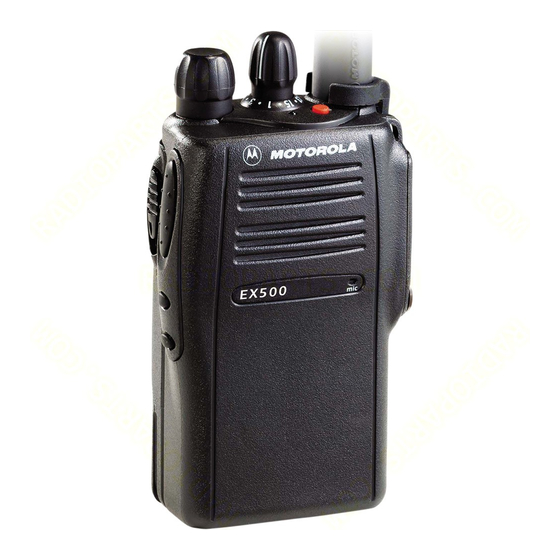
RADIO OVERVIEW PARTS OF THE RADIO EX500 Model Channel Selector Knob On/Off/Volume Knob Push-to-Talk (PTT) Button Side Button 1 (programmable) Side Button 2 (programmable) Top Button (programmable) LED Indicator Microphone English... -
Page 8: On/Off/Volume Knob
On/Off/Volume Knob Turns the radio on or off, and adjusts the radio’s volume. Channel Selector Knob Switches the radio to different channels. Push-to-Talk (PTT) Button Press and hold down this button to talk, release it to listen. Microphone Speak clearly into the microphone when sending a message. - Page 9 Button Short Press Initiates an Emer- Cancels your radio’s Emergency* gency Alert. Emergency status. Monitor/Perma- — Continually monitors the nent Monitor selected channel. Volume Set — — Battery Gauge — — Scan/Nuisance Toggles Scan on and Deletes a nuisance Channel Delete off.
-
Page 10: Indicator Tones
INDICATOR TONES High pitched tone English AUDIO INDICATORS FOR PROGRAMMABLE BUTTONS Low pitched tone Some programmable keys function as toggles (alternating between two different choices). Self Test Pass Tone These keys use audio indicators to indicate the change. Self Test Fail Tone Programmable Positive Indicator Tone Buttons... -
Page 11: Improved Audio Features
IMPROVED AUDIO FEATURES Low Level Expansion (LLE) The LLE feature of your radio improves voice quality by reducing unwanted background noise when receiving a message. It is compatible with most major types of audio processing systems available today. Companding Companding is a feature that allows further improvement of voice quality. - Page 12 NOTES English...
-
Page 13: Battery Information
This product is powered by a rechargeable battery. The following battery tips will help you obtain the highest performance and longest cycle life from your Motorola rechargeable battery. • Batteries are shipped uncharged from the factory. Always charge a new... -
Page 14: Charging Your Battery
• For optimum battery life and operation use only Motorola brand chargers. They were designed to operate as an integrated energy system. Charging your Battery When the battery level is very low, you need to recharge the battery before you can continue to use your radio. - Page 15 LED Indicator. Battery LED Indicator Level High Green Satisfactory Yellow Flashing Red Very Low None NOTE: If the Battery Gauge indicator does NOT appear, this indicates that the battery may not be a genuine Motorola product. English...
-
Page 16: Accessory Information
ACCESSORY INFORMATION Attaching the Battery 1 Fit the extensions at the bottom of the battery into the slots at the bottom of the radio. 2 Press the top part of the battery towards the radio until a click is heard. Note: It is important to make sure that both battery latches are secured. -
Page 17: Attaching The Antenna
Attaching the Antenna Removing the Antenna 1 Align the threaded end of the antenna with the Turn the antenna counterclockwise to remove it. radio’s antenna connector. 2 Turn the antenna clockwise to attach it. English... -
Page 18: Attaching The Side Connector Cover
Attaching the Side Connector Cover 1 Place the loop (attached to the side connector cover) over the antenna; then slide it down- ward until it touches the top of the radio. 2 Insert the tab on the top of the cover into the slot above the connector. -
Page 19: Adjusting The Radio's Volume
ADJUSTING THE RADIO’S VOLUME 1 Press and hold the Volume Set button (see page 17); you will hear a continuous tone. 2 Turn the On/Off/Volume knob (see page 16) and adjust the volume level. 3 Release the Volume Set button (see page 17). - Page 20 NOTES English...
-
Page 21: Radio Call Information
RADIO CALL INFORMATION RECEIVING A SELECTIVE CALL Selective Call allows a radio user to communicate with a single unit without involving other units in conversation. When you receive a selective call: • You will hear two alert tones. • The LED Indicator will light yellow. To answer the call, press the PTT button. -
Page 22: Talkaround
The Emergency Siren will cause the radio to sound a repetitive tone at the maximum volume. Press and release the Emergency button (see page 17) to initiate an Emergency Alarm. Press and hold the Emergency button (see page 17) to cancel the Emergency Alarm. Press and release the Emergency button (see page 17) to restart the Emergency sequence. -
Page 23: Power Level
To set the squelch level: Press the programmed Squelch button to toggle between the options of having normal squelch or tightening the squelch of your radio. A positive indicator tone indicates that the radio is operating in tight squelch, while a negative indicator tone indicates that the radio is operating in normal squelch. - Page 24 NOTES English...
-
Page 25: Scan
SCAN You can monitor several channels in order to receive any call that is transmitted on any of these channels. Sixteen different channels can be programmed into a scan list. Each channel can share the same scan list or have different scan lists assigned to them. -
Page 26: Adding A Deleted Nuisance Channel Back To The Scan List
ADDING A DELETED NUISANCE CHANNEL BACK TO THE SCAN LIST Press the Scan button ( the scan operation. Press the Scan button again to re-start the scan operation. SCAN CHANNEL DISCOVERY ALERT Sometimes you need to know which channel the radio has switched to during a scan operation. - Page 27 If Channel 2 is prioritized, the scan operation would change to Note: Even though your radio has switched to a non-priority channel, your radio will still check for activity on the priority channel. If some activity is detected there, the radio will switch to that prior- ity channel.
- Page 28 NOTES English...
-
Page 29: Warranty
Three (3) Years Product Accessories One (1) Year Motorola, at its option, will at no charge either repair the Product (with new or reconditioned parts), replace it (with a new or reconditioned Product), or refund the purchase price of the... - Page 30 Product item, transportation and insurance prepaid, to an authorized warranty service location. Warranty service will be provided by Motorola through one of its authorized warranty service locations. If you first contact the company which sold you the Product (e.g., dealer or communication service...
- Page 31 Product. K) Normal and customary wear and tear. VI. PATENT AND SOFTWARE PROVISIONS: MOTOROLA will defend, at its own expense, any suit brought against the end user purchaser to the extent that it is based on a claim that the...
- Page 32 A) that MOTOROLA will be notified promptly in writing by such purchaser of any notice of such claim; B) that MOTOROLA will have sole control of the defense of such suit and all negotiations for its settlement or compromise; and C) should the Product or parts become, or in MOTOROLA’s opinion be likely to become,...
-
Page 33: Accessories
JMNN4024 1320 mAH Li-Ion Ultra High Capacity Battery CHARGERS AAHTN3000 120V Single-Unit Rapid Charger, US Plug AAHTN3003 120V Multi-Unit Rapid Charger, US Plug Note: You must use the “C” version multi-charger or newer to be compatible with the EX500. English... -
Page 34: Antennas
ANTENNAS PMAD4012 VHF 136-155 MHz 9cm, Stubby PMAD4013 VHF 155-174 MHz 9cm, Stubby PMAD4014 VHF 136-155 MHz 14cm, Standard PMAD4015 VHF 155-174 MHz 14cm, Standard PMAD4023 VHF 150-161 MHz, 14cm PMAD4025 VHF 150-161 MHz, 9cm PMAE4002 403-433 MHz Stubby Antenna PMAE4003 433-470 MHz Stubby Antenna NAE6483 403-512 MHz Whip Antenna... - Page 35 Operates in Squelch squelch normal squelch Radio DOES Repeater/ Radio uses the NOT use the Talkaround repeater repeater EX500 Quick Reference Card Channel Selector Knob On/Off/Volume Knob Push-to-Talk (PTT) Button Side Button 1 (programmable) Side Button 2 (programmable) Button Function...
-
Page 36: Emergency Alarm
Turning On the Radio • Turn On/Off/Volume knob clockwise. Self Test Pass Tone will sound and green LED will light up if radio powers up successfully. If radio fails power up, the Self Test Fail Tone will sound. Turning Off the Radio •... - Page 38 MOTOROLA and the Stylized M Logo are registered in the US Patent & Trademark Office. All other product or service names are the property of their respective owners. © Motorola, Inc. 2005. Inc. All rights reserved. Printed in U.S.A. MOTOROLA, Le logo stylisé M,et intelligence universelle sont des marques de Motorola, Inc.