Table of Contents
Advertisement
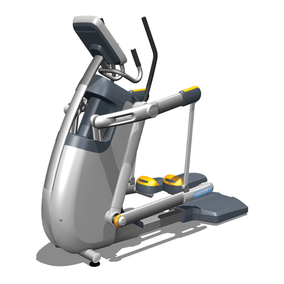
C100i Adaptive Motion Trainer
C100i Adaptive Motion Trainer
Warning: This service manual is for use by Precor trained service providers only.
If you are not a Precor Trained Servicer, you must not attempt to service any Precor Product;
Call your dealer for service.
This document contains information required to perform the majority of troubleshooting, and
replacement procedures required to repair and maintain this product.
This document contains general product information, software diagnostic procedures (when
available), preventative maintenance procedures, inspection and adjustment procedures,
troubleshooting procedures, replacement procedures and electrical block and wiring diagrams.
Acrobat Reader Users:
To move directly to a procedure, click the appropriate procedure in the bookmark section to the
left of this page. You may "drag" the separator bar between this page and the bookmark section
to change the size of the page being viewed.
© 2006 Precor Incorporated
Unauthorized Reproduction and Distribution Prohibited By Law
20039-154
Page 1
Advertisement
Table of Contents
Troubleshooting

Related Manuals for Precor C100i


Summary of Contents for Precor C100i
- Page 1 C100i Adaptive Motion Trainer Warning: This service manual is for use by Precor trained service providers only. If you are not a Precor Trained Servicer, you must not attempt to service any Precor Product; Call your dealer for service. This document contains information required to perform the majority of troubleshooting, and replacement procedures required to repair and maintain this product.
- Page 2 (positive) wire must be disconnected from the battery. Always ensure that the C100i external power supply is unplugged from the wall outlet and the red (positive) wire is removed from the battery when you inspect or adjust the C100i, or when you isolate, remove, or replace an C100i component.
- Page 3 Caution statements included in this manual are listed below: • When it is necessary to lift or move the C100i, ensure that the C100i has adequate support and that you use proper lifting techniques. When the rear platform is removed, the C100i may be lifted from the rear and moved like a “wheelbarrow”.
- Page 4 Cord management must be maintained. General Information For the latest exploded view, part number and part pricing information, visit the Precor dealer website at “www.precor.com/connection”. Tools Required...
- Page 5 • Wipe down the covers, handlebars and stairarms with a damp cloth. Daily Maintenance Clean the C100i’s frame, covers, stairarms and foot pedals using water or a 30:1 solution of ® Simple Green and water. Wipe the surface of the electronic console with a damp sponge or soft Athletix ®...
- Page 6 Check for excessive noise during vertical and horizontal operation. Replace the side covers. Re-level the C100i to ensure that all five “feet” are in contact with the floor. On-Site Preventive Maintenance (Service Technician) When you are called to service a C100i, perform these preventive maintenance activities: •...
- Page 7 Precor banner displayed. If the access is aborted, it will be necessary to start over from the beginning. Refer to Diagram 3.1.
- Page 8 Battery Test • Stride Position Test Procedure Start pedaling the C100i using a vertical motion. Using the RESET key and the numeric keypad, press keys RESET,5,1,7,6,5,7,6,1, sequentially. Hardware Validation will scroll across the display followed by DISPLAY TEST. Press the OK key, the upper most group of LED’s will illuminate on the display. Check the display to ensure that all LED segments are illuminated.
- Page 9 C100i Adaptive Motion Trainer 13. Press the OK key, PWRB will be displayed with the current power bit reading. Pressing the resistance will change the power bit setting. 14. Press the CLEAR key then the key, RPM TEST will scroll across the display.
- Page 10 Error Log Procedure Start pedaling the C100i using a vertical motion. With the PRECOR banner scrolling, press the keys RESET,6,5, sequentially. DIAGS-INFORMATION DISPLAY will scroll across the display. Use the keys to move to the desired display shown in the list above.
- Page 11 25. Press the CLEAR key to exit the lower SW display. 26. SER. NUMBER display. Press the OK key. 27. The C100i’s serial number will be displayed. The serial number may be incorrect or not displayed if the upper PCA has been replaced.
- Page 12 C100i Adaptive Motion Trainer 33. Press the OK key, the most recent error will be displayed first. 34. Use the keys to move through the list of errors. The error messages will list the error name, the odometer reading when the error occurred, the hour meter when the error occurred and the drive motor current reading when the error occurred.
- Page 13 Set Max Pause Time • Set Cool Down Time Procedure Start pedaling the C100i using a vertical motion. With the banner scrolling, press keys RESET,5,6,5,1,5,6,5, sequentially. Use the keys to move to the desired display shown in the list above.
- Page 14 C100i Adaptive Motion Trainer 17. SET COOL DOWN TIME display. Press the OK key. 18. Use the keys to select the cool down time from 0 to 5 minutes. 19. Press the BACK key to exit the set cool down time display.
- Page 15 If an appropriate software version is not available the information below must be forwarded to Precor customer support. This information will be used to correct and create new software, whenever it is appropriate.
- Page 16 The C100i must be “powered down” before the upload procedure can be initiated. Ensure that the C100i has not be used for a sufficient time to allow the lower PCA to completely discharge. The light emitting diode on the lower PCA will go out when the power supply is discharged, approximately 45 seconds.
- Page 17 PCA to completely discharge. The light emitting diode on the lower PCA will go out when the power supply is discharged. Start pedaling the C100i, after it has been allowed to power down, the C100i will now be operating on the newly uploaded software.
- Page 18 Be on the alert for unusual rubbing, hitting, grinding, or squeaking noises. Ensure that the C100i is properly leveled, that all five “feet” are in contact with the floor and there is no side to side rocking.
- Page 19 C100i Adaptive Motion Trainer Procedure 5.1 - Measuring the Resistance of a Generator Caution If a external power supply is connected to the C100i, disconnect the external power supply from the C100i before continuing with this procedure. Procedure Remove the right side cover per Procedure 7.12.
- Page 20 C100i Adaptive Motion Trainer Diagram 5.1 - Lower PCA 3 PHASE BATTERY GEN IN LOAD Page 20...
- Page 21 C100i Adaptive Motion Trainer Procedure 5.2 - Inspecting and Adjusting Belt Tension WARNING Before continuing with this procedure, review the Warning and Caution statements listed in Sec- tion One, Things You Should Know. Procedure Primary Belt Adjustment Remove the front, rear, left and right side covers per Procedure 7.12.
- Page 22 C100i Adaptive Motion Trainer Brake Belt Adjustment Check the tension of the brake belt using the belt gauge, shown in Diagram 5.2. Belt tension should be 110 lbs ± 10 lbs. If the belt tension is incorrect, adjust the belt tension using the adjustment bolt shown in Diagram 5.3.
- Page 23 C100i Adaptive Motion Trainer Procedure 5.3 - Drive Belt Alignment The alignment of the drive belt between the generator pulley and the primary pulley is important. Incorrect alignment will cause premature belt wear and/or belt noise. Remove front, rear, left and right side covers per Procedure 7.12.
- Page 24 C100i Adaptive Motion Trainer Procedure 6.1 - Troubleshooting Interconnect Cable Anti-static kits can be ordered from Precor (part number 20024-101). Troubleshooting the Upper Interconnect Cable Remove the display’s rear cover. Remove the right side cover. Disconnect the interconnect cable from the upper PCA and the lower PCA.
- Page 25 Attach the anti-static wrist strap to your arm, then connect the ground wire of the wrist strap to the units frame. If the C100i powers up and functions normally until a particular key(s) is pressed, skip to step 10. If a “stuck key” message is immediately displayed when the C100i is powered up, continue with the next step.
- Page 26 C100i Adaptive Motion Trainer If a “stuck key” message is not displayed when the C100i is powered up, replace the display housing front panel. The display housing front panel is equipped with the keypad. If you have performed all of the procedures above and have been unable to correct the problem, call Precor customer service.
- Page 27 If the optional external power supply is not equipped, skip to step 5. Disconnect the optional external power supply from the C100i and measure between the inner and outer sleeves of the power supply’s output jack with a DC voltmeter. You should measure approximately 18 VDC.
- Page 28 C100i Adaptive Motion Trainer Diagram 6.2 - Partial View of Lower PCA TP14 DGND TP24 7.5V 10. Troubleshoot the upper to lower PCA interconnect cables per Procedure 6.1. 11. If the upper to lower interconnect cable is found to be good, replace the upper PCA.
- Page 29 Second, the generator is used to charge the C100i’s internal battery. Lastly, one of the generators six phase output windings is monitored to determine when the unit is in use and when it is idle. This system also determines the stride rate by determining the operating speed (output frequency) of the monitored generator winding.
- Page 30 C100i Adaptive Motion Trainer Procedure 6.5 - Troubleshooting Hand Held Heart Rate Circuit Description The hand held heart rate system is actually a dual system, that is, it can accept a heart rate signal from either the hand held heart rate contacts on the unit’s handlebar or from a Polar heart rate chest strap transmitter.
- Page 31 C100i Adaptive Motion Trainer No hand held reading - Normal chest strap reading Access the diagnostic program (Procedure 3.2). Advance to the heart rate display portion of the diagnostic program. Verify that a hand held signal is not being accepted by firmly grasping both the right and left hand held contacts on the handlebars.
- Page 32 C100i Adaptive Motion Trainer No hand held reading - No chest strap reading 11. Access the diagnostic program (Procedure 3.2). Advance to the heart rate display portion of the diagnostic program. Verify that neither a chest strap signal or a hand held signal is being accepted with either a heart rate test transmitter or a chest strap transmitter.
- Page 33 Procedure 7.1 - Replacing the Display Enclosure or Upper PCA Anti-static kits (part number 20024-101) can be ordered from Precor. The keyboard is part of the display housing front panel. If the keyboard is not functioning properly, replace the display housing front panel.
- Page 34 13. Reconnect the interconnect and heart rate cables to the upper PCA. 14. Remove the ground wire of the wrist strap from the C100i frame, then remove the wrist strap from your arm. 15. Position the display’s rear cover on the display housing. Replace and tighten the display mounting screws.
- Page 35 C100i Adaptive Motion Trainer Procedure 7.2 - Replacing the Lower PCA Remove the right side cover. WARNING Before continuing with this procedure, review the Warning and Caution statements listed in Section One, Things You Should Know. Attach the wrist strap to your arm, then connect the ground wire of the wrist strap to the C100i frame.
- Page 36 C100i Adaptive Motion Trainer Remove the ground wire of the wrist strap from the C100i frame, then remove the wrist strap from your arm. Re-install the right side cover, then check the operation of the C100i as described in Section Four.
- Page 37 C100i Adaptive Motion Trainer Procedure 7.3 - Replacing the Interconnect Cable Before you install a new interconnect cable, ensure that the interconnect cable is defective as described in Procedure 6.1. WARNING Before continuing with this procedure, review the Warning and Caution statements listed in Section One, Things You Should Know.
- Page 38 11. Dress the interconnect cable along the frame as shown in Diagram 7.3 and secure it with four tie wraps. 12. Replace the display rear cover and the right side cover. 13. Check the operation of the C100i as described in Section Four Page 38...
- Page 39 C100i Adaptive Motion Trainer Procedure 7.4 - Replacing Primary Belt WARNING Before continuing with this procedure, review the Warning and Caution statements listed in Section One, Things You Should Know. Remove the left side cover. Remove the bolt that fastens the left side upper arm weldment. Remove the handlebar from its mount and lower the assembly to the floor.
- Page 40 C100i Adaptive Motion Trainer Tension the primary belt per Procedure 5.2. Slide the upper connecting rod half into the lower connecting rod half and fasten them with the hardware removed in step 4. Torque the connecting rod bolts to 17 - 21 foot pounds (200 - 250 inch pounds).
- Page 41 C100i Adaptive Motion Trainer Procedure 7.5 - Replacing Brake Belt WARNING Before continuing with this procedure, review the Warning and Caution statements listed in Section One, Things You Should Know. Remove the rear covers, and the left and right side covers.
- Page 42 C100i Adaptive Motion Trainer Remove the four screws from the belt bracket and remove the belt bracket. Remove the brake belt by lifting it over the top and bottom edges of the brake assembly mounting bracket. Set the replacement belt on the brake assembly, with the four holes in the belt aligned with the four holes in the brake sheave, by lifting the belt over the bottom and top edges of the brake assembly mounting plate.
- Page 43 C100i Adaptive Motion Trainer Procedure 7.6 - Replacing the Primary Pulley Assembly WARNING Before continuing with this procedure, review the Warning and Caution statements listed in Section One, Things You Should Know. Remove the left and right side covers and the front cover.
- Page 44 C100i Adaptive Motion Trainer 10. Set the replacement primary pulley assembly in its mounting position and fasten it with the hardware removed in step 9. 11. Set the primary belt in its mounting location with the belt routed in front of the idler pulley.
- Page 45 C100i Adaptive Motion Trainer Procedure 7.7 - Replacing a Generator WARNING When the unit is used, stairarms are in motion or the generator is rotated by any means, the generator will produce potentially hazardous voltages even when the battery is disconnected.
- Page 46 C100i Adaptive Motion Trainer Reconnect the generator midpoint connections as follows. Connect the two red wires from the generators eddy current magnet to the green and brown wires in the midpoint cable, the order does not matter. Connect the red, white and black wires from the generator to the red, white and black wires in the midpoint cable.
- Page 47 Connect the red wire removed in step 2 to the positive terminal (red dot) of the battery and the black wire removed in step 2 to the negative terminal of the battery. Replace the left side cover. Test the C100i per Procedure 4. Page 47...
- Page 48 C100i Adaptive Motion Trainer Procedure 7.9 - Replacing a Stairarm Use a flat bladed screwdriver to depress the tab in the lower cover and slide the lower cover up on the rear link. See Diagram 7.25. Remove the two bolts that fasten the stairarm to the rear link assembly. Lower the stairarm to the floor.
- Page 49 C100i Adaptive Motion Trainer Remove the stairarm from the front arm assembly. Remove the two screws that fasten the foot pedal to the stairarm and remove the foot pedal. There are two bearings in the front arm assembly. The inner race of the bearings is not attached to the bearings and will come loose when the stairarm is removed.
- Page 50 C100i Adaptive Motion Trainer 11. Carefully, slide the stairarm into the front arm assembly. The inner race of the far bearing will probably slide part way out of the bearing. Using a small blunt tool, gently tap the race back into the bearing.
- Page 51 C100i Adaptive Motion Trainer Procedure 7.10 - Replacing a Upper Arm Casting Note: This procedure was for use on older AMT’s that have a two piece upper. See Procedure 7.14 for replacing a two piece upper arm with a one piece upper arm.
- Page 52 C100i Adaptive Motion Trainer Procedure 7.11 - H-Brake Removal and Replacement Remove the lower rear cover, the left and right lower rear side covers, upper rear cover, left side cover and right side cover per Procedure 7.12. Remove the nuts and bolts that retain both tie rods to the H-brake assembly. See Diagram 7.12...
- Page 53 C100i Adaptive Motion Trainer Diagram 7.14 - H-Brake Mounting Bolts Mounting Bolts Set the replacement H-brake in its mounting position, If possible have an assistant support the H-brake, and replace the four H-brake mounting bolts removed in step 4. Torque the H-brake mounting bolts to 200-250 inch pounds (17 - 21 foot pounds).
- Page 54 C100i Adaptive Motion Trainer Procedure 7.12 - Replacing a Cover Cover Removal Using a flat bladed screwdriver, carefully pry both sides of the lower rear cover loose from its mounting. See Diagram 7.16. Remove the lower rear cover. Diagram 7.16 - Lower Rear Cover...
- Page 55 C100i Adaptive Motion Trainer Support the upper rear cover and remove both screws from the bottom of the cover. See Diagram 7.18. Remove the upper rear cover. Diagram 7.18 - Upper Rear Cover Upper Rear Cover Remove two screws from the bottom edge of both side covers and remove both covers.
- Page 56 C100i Adaptive Motion Trainer Cover Installation Slide the front cover into its mounting position and fasten it with the two screws removed in step 5. Slide the right side cover into its mounting position with the lip on the cover behind the upper dark gray cover, behind the front cover and the tab at the bottom of the side cover into the clip in the lower cover.
- Page 57 C100i Adaptive Motion Trainer 10. Set the upper rear cover in its mounting position. First, slide the upper portion of the cover into place. See Diagram 7.23. Press downward on the rear portion of the cover and snap it into place.
- Page 58 C100i Adaptive Motion Trainer Procedure 7.13 - Replacing a Rear Link Remove the screws from the lower half of the upper cover. Remove the upper half of the upper cover. The lower half of the upper cover will be removed later. See Diagram 7.24.
- Page 59 C100i Adaptive Motion Trainer the rear link. These bolts thread into a free floating shaft, remove one of the two. Thread a 3/8 X 16 bolt that is approximately 2 inches long with jam nut, not provided, into the hole that the bolt was just removed from and tighten the jam nut. The bolt and jam nut will hold the shaft in place and allow removal of the remaining mounting bolt.
- Page 60 C100i Adaptive Motion Trainer Procedure 7.14 - Upper Arm Replacement Remove the two screws that fasten the plastic covers on the end of the upper arm. Remove the top cover and slide the bottom cover down the rear link to the stairarm.
- Page 61 C100i Adaptive Motion Trainer Remove, and retain for later use, the large snap ring from the center of the upper arm and remove and save the large black plastic washer. Remove the upper arm from AMT and discard. Slide both of the inner bearing races and black plastic spacer off of the upper arm mounting shaft and discard.
- Page 62 C100i Adaptive Motion Trainer 11. Slide the large black washer, removed in step 8, onto the upper arm mounting shaft and fasten the upper arm with the snap ring removed in step 8. replace the large end cap removed in step 6. It may be necessary to replace the large end cap if it no longer fits securely in the upper arm.
- Page 63 C100i Adaptive Motion Trainer Procedure 7.15 - Front Arm Replacement Slide the cover up on the moveable handlebar, remove the two bolts that fasten the moveable handlebar to front arm. Remove the moveable handlebar from the front arm. See Diagram 7.32.
- Page 64 C100i Adaptive Motion Trainer 10. Remove the spacer, the inner race, two large washers and a wave washer from the stairarm. The clearance between the stairarm shaft and the inner race is very small. It is very easy to jam the inner race on the stairarm shaft.
- Page 65 C100i Adaptive Motion Trainer Wiring Diagram 8.1 - C100i Self Powered Page 65...
- Page 66 C100i Adaptive Motion Trainer Block Diagram 8.2 - C100i Self Powered Page 66...