Technics SA-EX310 Service Manual
Av control stereo receiver
Hide thumbs
Also See for SA-EX310:
- Operating instructions manual (24 pages) ,
- Operating instructions manual (24 pages) ,
- Operating instructions manual (25 pages)
Table of Contents
Advertisement
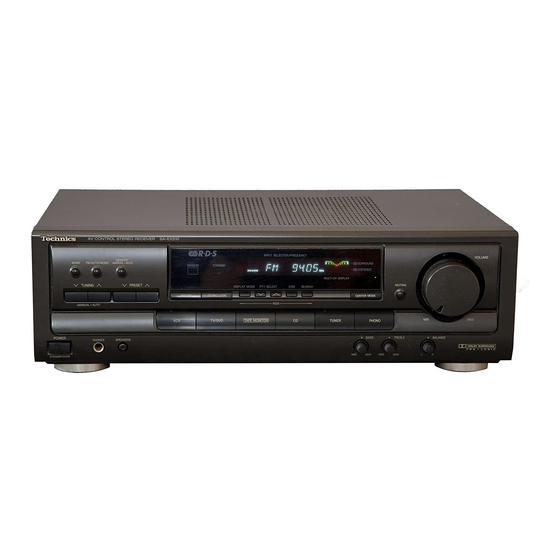
AV Control Stereo Receiver
*
Manufactured under license from Dolby Laboratories Licensing Corporation. Additionally licensed
under one or more of the following patents: U.S. numbers 3,632,886,3,746,792 and 3,959,590;
Canadian numbers 1,004,603 and 1,037,877.
"Dolby" and the double-D symbol are trade marks of Dolby Laboratories Licensing Corporation.
SPECIFICATIONS\
ÒÅÕÍÈ×ÅÑÊÈÅ ÕÀÐÀÊÒÅÐÈÑÒÈÊÈ
PROTECTION CIRCUITRY\
CAUTION FOR AC MAIN LEADS\
ÏÈÒÀÍÈß ÏÅÐÅÌÅÍÍÎÃÎ ÒÎÊÀ
OPERATION CHECKS AND MAIN COMPONENT REPLACEMENT
PROCEDURES\
ÏÐÎÂÅÐÊÀ ÐÀÁÎÒÎÑÏÎÑÎÁÍÎÑÒÈ È ÇÀÌÅÍÀ ÎÑÍÎÂÍÛÕ
ÊÎÌÏÎÍÅÍÒÎÂ
FAN MOTOR TROUBLESHOOTING\
TROUBLESHOOTING\
BLOCK DIAGRAM\
TERMINAL FUNCTIONS OF IC's\
ÈÍÒÅÃÐÀËÜÍÛÕ ÌÈÊÐÎÑÕÅÌ
TERMINAL GUIDE OF IC's, TRANSISTORS & DIODES\
ÈÍÒÅÃÐÀËÜÍÛÕ ÌÈÊÐÎÑÕÅÌ, ÒÐÀÍÇÈÑÒÎÐÎÂ È ÄÈÎÄÎÂ
SCHEMATIC DIAGRAMS\
PRINTED CIRCUIT BOARDS\
WIRING CONNECTION DIAGRAM\
CABINET PARTS LOCATION\
REPLACEMENT PARTS LIST\
RESISTORS & CAPACITORS\
PACKAGING\
ÓÏÀÊÎÂÊÀ
ÑÈÑÒÅÌÀ ÇÀÙÈÒÛ
ÌÅÐÛ ÁÅÇÎÏÀÑÍÎÑÒÈ ÏÐÈ ÐÀÁÎÒÅ ÑÎ ØÍÓÐÎÌ
ÍÅÈÑÏÐÀÂÍÎÑÒÈ ÄÂÈÃÀÒÅËß ÎÕËÀÆÄÅÍÈß
ÍÅÈÑÏÐÀÂÍÎÑÒÈ È ÌÅÒÎÄÛ ÈÕ ÓÑÒÐÀÍÅÍÈß
ÁËÎÊ-ÑÕÅÌÀ
ÔÓÍÊÖÈÎÍÀËÜÍÎÅ ÍÀÇÍÀ×ÅÍÈÅ ÂÛÂÎÄÎÂ
ÏÐÈÍÖÈÏÈÀËÜÍÛÅ ÑÕÅÌÛ
ÏÅ×ÀÒÍÛÅ ÏËÀÒÛ
ÑÕÅÌÀ ÑÎÅÄÈÍÅÍÈß
ÐÀÑÏÎËÎÆÅÍÈÅ ×ÀÑÒÅÉ ÊÎÐÏÓÑÀ
ÑÏÈÑÎÊ ÇÀÏÀÑÍÛÕ ×ÀÑÒÅÉ
ÐÅÇÈÑÒÎÐÛ È ÊÎÍÄÅÍÑÀÒÎÐÛ
®
ORDER NO. MD9707082C2
SA-EX310
Colour
(K) . . . . . . . . Black Type
Area
Suffix for
Area
Model No.
(E)
Europe
(EB)
Great Britain
(EG)
Germany and Italy
ÖÎÊÎËÅÂÊÀ ÂÛÂÎÄÎÂ
© 1997 Matsushita Electronics (S) Pte. Ltd.
All rights reserved. Unauthorized copying and
distribution is a violation of law.
Receiver
Colour
(K)
Advertisement
Table of Contents

Related Manuals for Technics SA-EX310


Summary of Contents for Technics SA-EX310
- Page 1 ORDER NO. MD9707082C2 Receiver AV Control Stereo Receiver SA-EX310 Colour (K) ..Black Type Area Suffix for Area Colour Model No. Europe (EB) Great Britain (EG) Germany and Italy Manufactured under license from Dolby Laboratories Licensing Corporation. Additionally licensed under one or more of the following patents: U.S.
-
Page 2: Specifications
SA-EX310 Specifications FM Tuner Section Frequency range 87.50 — 108.00 MHz 38kHz -50 dB (-55 dB, IHF) Sensitivity Channel balance (250 Hz - 6.3 kHz ) +1.5 dB 1.5 µV / 75Ω S/N 30 dB 1.2 µV Limitting point 1.3 µV / 75Ω... - Page 3 SA-EX310 Caution for AC Main Leads (For “EB” area code model only.) THIS PLUG IS NOT WATERPROOF—KEEP DRY. For your safety, please read the following text carefully. Before use Remove the connector cover. This appliance is supplied with a moulded three pin mains plug for your safety and convenience.
-
Page 4: Operation Checks And Main Component Replacement Procedures
SA-EX310 Operation Checks and Main Component Replacement Procedures "ATTENTION SERVICER" Some chassis components may have sharp edges. Be careful when disassembling and servic- ing. Please take note that the diagrams shown are for model SA-EX510 which is similar to SA- EX310. - Page 5 SA-EX310 To Remove Front Panel, Panel P.C.B., Power Switch Step 4 P.C.B. and Headphone Jack P.C.B. Remove the Volume Knob and Nut. Step 1 Step 6 Remove the top cabinet. Step 5 Pull out 3 knobs. Step 2 Step 7 Step 3 Panel P.C.B.
- Page 6 SA-EX310 MAIN P.C.B. (Solder Side) Step 8 Connect the front panel to the main P.C.B. as shown. • Check the Main P.C.B. as shown • [XTB3+8FFZ] (Black) [XTB3+20JFZ] (Black) Main Component Replacement Procedures 1. Replacement of the Power IC and...
- Page 7 SA-EX310 Regulator transistor (Q701,Q708) [2SD2374PQAU,2SB1548PQAU] Step 5 Power IC (IC602) [XTW3+15T] [RSN3305-P] Installation of the bottom cover after replacement Step 1 Step 3 Screw (XTB3+8J) (Prepare this screw to fix the bottom cover.) Ribs Lugs Step 2 Align the ribs of bottom cover into the lugs.
- Page 8 SA-EX310 Screws AC In / Out P.C.B. Tuner & Tuner Pack P.C.B. Pro Logic P.C.B. Transformer P.C.B. Power P.C.B. Fig.3 Front Panel About 9 cm (A long straight screwdriver connot be used) –––OFFSET SCREWDRIVER––– •The PROTO offset screwdriver No.34- is recommended for use in the application above.
- Page 9 SA-EX310 Fan Motor Troubleshooting The Model SA-EX310 employ fan motor error sensing electronics. If the cooling fan is not operating and "OVER LOAD" is displayed on the FL display, check the fan motor and its driving circuit . "OVER LOAD" is displayed on the FL display.
-
Page 10: Troubleshooting
SA-EX310 Troubleshooting This unit has test points on each circuit board block for use in troubleshooting. CONNECTION Connect either a CD player, tape deck or AF oscillator to the input terminals of the unit. REQUIRED ITEMS 1. Testing with a CD player ––––––– Test disc (SZZP1054C / first progarm, 1kHz, 0dB) 2. - Page 11 SA-EX310 NORMAL WAVEFORMS OF AMPLIFIER CIRCUIT AND LIKELY FAULTY BLOCKS Likely faulty block if the normal CD player Tape deck AF oscillator waveform shown at the left is not present. L1/R1 Input selector block IC402 & area 0.5msec 2V 1msec 500mV...
- Page 12 SA-EX310 Run the tape deck Run the CD player Run the AF oscillator QZZCLA 315Hz, 0dB SZZP1054C/first program Oscillator output 1kHz, 0dB at 500Hz, 200mV Note: Connect the '+' probe of Using the Oscilloscope, check the output waveforms at the test points on...
- Page 13 SA-EX310 NORMAL WAVEFORMS OF AMPLIFIER CIRCUIT AND LIKELY FAULTY BLOCKS Likely faulty block if the normal CD player Tape deck AF oscillator waveform shown at the left is not present. Power limiter block Q551 to Q552 & area 0.5msec 200mV*...
-
Page 14: Block Diagram
SA-EX310 Block Diagram... - Page 15 SA-EX310...
- Page 16 SA-EX310...
- Page 17 SA-EX310...
-
Page 18: Terminal Functions Of Ics
SA-EX310 Terminal Functions Of ICs • IC901 (M38B53M4053F) System Microprocessor Mark Mark Function Function KEY4~KEY1 I Key matrix detect terminal 33~48 SEG16~SEG1 FL segment signal output THERM/ O VLD Thermal/Over load detect terminal 49~58 DEG1~DEG10 FL digit signal output FM_ST... -
Page 19: Schematic Diagram
SA-EX310 MTZJ9R1CTA 1N5402BM21 RVD1SS133TA MTZJ5R1BTA LN846RPH MTZJ6R2BTA SB360L6508 1SR35200TB MTZJ5R6BTA Cathode MTZJ15CTA MTZJ7R5CTA 1SS291TA MTZJ6R8BTA MA165TA Anode Cathode MTZJ4R7BTA Cathode MTZJ3R9ATA Cathode MTZJ10CTA MTZJ27DTA Anode Anode Anode MTZJ24DTA Schematic Diagram (All schematic diagrams may be modified at any time with the development of new technology) Note : •... - Page 20 SA-EX310 Schematic Diagram...
- Page 21 SA-EX310...
- Page 22 SA-EX310...
- Page 23 SA-EX310...
- Page 24 SA-EX310...
- Page 25 SA-EX310...
- Page 26 SA-EX310...
- Page 27 SA-EX310...
- Page 28 SA-EX310...
- Page 29 SA-EX310...
-
Page 30: Printed Circuit Board
SA-EX310 Printed Circuit Board PANEL P.C.B. (REP2445D-S) MOTOR P.C.B. (REP2445D-S) HEADPHONE JACK P.C.B. (REP2445D-S) - Page 31 SA-EX310 POWER SWITCH P.C.B. (REP2445D-S)
- Page 32 SA-EX310 MAIN P.C.B. (REP2444C-M)
- Page 33 SA-EX310...
- Page 34 SA-EX310 TUNER P.C.B. (REP2158A-T)..EG (REP2158D-T)..E/EB...
- Page 35 SA-EX310 TRANSFORMER P.C.B. (REP2444C-M) POWER P.C.B. (REP2446D-P)..E/EG (REP2446E-P)..EB...
- Page 36 SA-EX310 IN / OUT TERMINAL P.C.B. (REP2446D-P)..E/EG (REP2446E-P)..EB AC IN/OUT P.C.B. (REP2446D-P)..E/EG (REP2446E-P)..EB...
-
Page 37: Wiring Connection Diagram
SA-EX310 Wiring Connection Diagram SOLDER SIDE JK402 REC (OUT) IN / OUT TAPE TERMINAL TUNER P.C.B PLAY (IN) P.C.B JK403 TV/ DVD SOLDER SIDE FM ANT JK101 JK404 AM ANT CN402 CN401 CN102 CN101 7 ..1 7 ..1... -
Page 38: Cabinet Parts Location
SA-EX310 Cabinet Parts Location JK794 (AC IN/OUT P.C.B) (IN/OUT TERMINAL P.C.B) JK402 W701 W752 CN751 JK403 JK404 JK601 T751 JK602 CN701C CN401 (POWER P.C.B) CN701B JK405 CN701A JK351 JK101 CN752 CN402 E601 JK401 (TUNER PACK E401 CN901 P.C.B) CP402 (TUNER P.C.B) -
Page 39: Replacement Parts List
SA-EX310 Replacement Parts List Notes: * Important safety notice : Components identified by mark have special characteristics important for safety. Furthermore, special parts which have purposes of fire-retardant (resistors), high-quality sound (capacitors), low-noise (resistors), etc. are used. When replacing any of components, be sure to use only manufacturer's specified parts shown in the parts list. - Page 40 SA-EX310 Ref No. Part No. Part Name & Description Remarks Ref No. Part No. Part Name & Description Remarks Ref No. Part No. Part Name & Description Remarks D705 MTZJ6R2BTA DI O DE S960 EVQ21405R SW, TUNER L105 RLQZB822KT-D TAPING COIL...
- Page 41 SA-EX310 Ref No. Part No. Part Name & Description Remarks Ref No. Part No. Part Name & Description Remarks Ref No. Part No. Part Name & Description Remarks XBA2C50TB0 FUSE JK402 SJF3069N JK, LINE IN RJA0019-2K AC CORD (SF) [M]EG E...
- Page 42 SA-EX310 Ref No. Part No. Val u es & Remarks Ref No. Part No. Val u es & Remarks Ref No. Part No. Val u es & Remarks Ref No. Part No. Val u es & Remarks R515 ERDS2TJ474T 470K...
- Page 43 SA-EX310 Ref No. Part No. Val u es & Remarks Ref No. Part No. Val u es & Remarks Ref No. Part No. Val u es & Remarks Ref No. Part No. Val u es & Remarks R949 ERDS2TJ103T 1/ 4 W [M]...
- Page 44 SA-EX310 Ref No. Part No. Val u es & Remarks Ref No. Part No. Val u es & Remarks Ref No. Part No. Val u es & Remarks Ref No. Part No. Val u es & Remarks C440 ECBT1E103ZF5 0. 0 1...
- Page 45 SA-EX310 Ref No. Part No. Val u es & Remarks Ref No. Part No. Val u es & Remarks Ref No. Part No. Val u es & Remarks Ref No. Part No. Val u es & Remarks C1036 ECBT1H101KB5 100P...