Table of Contents
Advertisement
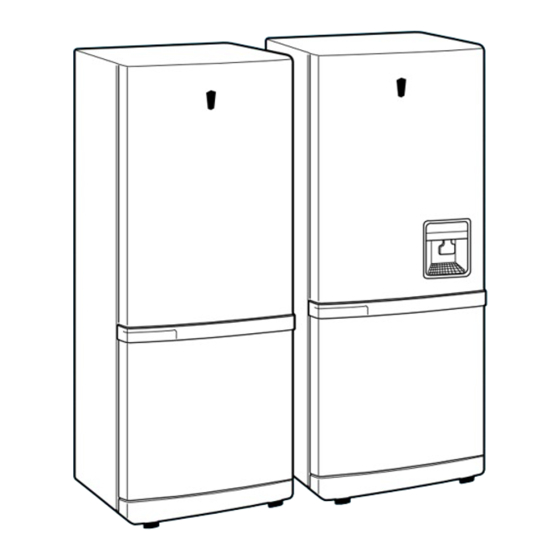
REFRIGERATOR
SR-L676EV
SR-L678EV
SR-L626EV
SR-L628EV
REFRIGERATOR
Model : SR-L676EV
SR-L678EV
SR-L626EV
SR-L628EV
CONTENTS
1. Precautions
3. Electrical Part Specifications & Standard
4. Circuit Diagram
5. Functions & Operating Instruction
8. Parts List
9. Disassembly & Assembly
12. Specifications of Main Components
GREEN
Advertisement
Table of Contents
Troubleshooting

Related Manuals for Samsung SR-L676EV


Summary of Contents for Samsung SR-L676EV
- Page 1 REFRIGERATOR Model : SR-L676EV SR-L678EV SR-L626EV SR-L628EV GREEN REFRIGERATOR CONTENTS 1. Precautions 2. Product Specifications 3. Electrical Part Specifications & Standard 4. Circuit Diagram 5. Functions & Operating Instruction 6. Circuit Descriptions 7. Troubleshooting 8. Parts List 9. Disassembly & Assembly 10.
-
Page 2: Product Specifications
Starting type RSCR RSCR Freon α-15(ESTER) Oil charge Freezer Split Fin Type Evaporator Refrigerator Split Fin Type Condenser Forced & Natural Convection Type Dryer Molecular Sieve XH-9 Capillary tube ID0.85XL2500 3.79kg/cm Earth screw BSBN(Brass screw) Door switch 250V/0.5A Samsung Electronics... -
Page 3: Defrost Cycle
OSRAM DEULX S/E IIW REF. M O T O R - G E A R E D REF. M 2 B C 1 8 A R 0 2 M 2 L C 1 8 A R 0 2 Samsung Electronics... - Page 4 5. Function & Operating Instr uction 5-1 Product Dimension • "X" "Y" Remarks MODEL 1750.0 SRG-L678EV 994.5 1509.7 "X" SRG-L676EV 1750.0 994.5 1509.7 "Y" 1750.0 SR-L628EV 994.5 1459.7 "X" SR-L626EV 1750.0 994.5 1459.7 "Y" Samsung Electronics...
- Page 5 • • • Take out the water bottle with the bottom latch pressed. • • • • Tray disassembly Pull it out by following • the arrow. • • Freezing compartment • Ice compartment • Vegetable compartment Samsung Electronics...
- Page 6 Compressor → Sub condenser → Cluster pipe → Hot pipe → Dryer → Capillary tube → R-Evaporator → F-Evaporator → Accumulator → Suction pipe → Compressor SIDE CLUSTER PIPE CAPILLARY TUBE ACCUMULATOR F-EVAPORATOR SUCTION PIPE DRYER HOT PIPE SUB CONDENSER COMP. Samsung Electronics...
- Page 7 5-4 Cool Air Circulation R-FAN MOTOR R-EVAPORATOR SUCTION AIR F-FAN MOTOR F-EVAPORATOR OUTPUT AIR SUCTION AIR Samsung Electronics...
- Page 8 “LOW · MED”. 3) When power turns on “MED” is automatically selected. Category Pressed twice Pressed 3 times Pressed 4 times Remark Initial power on Pressed once Indicator Lamp MED·HIGH HIGH LOW·MED Reference Temp. –17.5˚C –19.5˚C –21˚C –15˚C –16.5˚C Samsung Electronics...
- Page 9 The power refrigeration finishes if COMP and R-FAN does not reach –4˚C even though 2 and 30 hour operation. If it is selected, refrigerator is controlled by the fixed notch. 3) When the power freezing · refrigeration are selected simultaneously Each function is carried out at the same time. Samsung Electronics...
- Page 10 4) If the alarm is selected by the button, the alarm rings regularly. 5) Alarm by the alarm button includes only door open. 6) Model SR-L676EV, SR-L626EV follows the above alarm procedure without alarm select button. C. Forced starting · Forced defrosting (beep sound) 1) If the forced starting ·...
-
Page 11: Test Function
C. Test mode release 1) If the test button is pressed twice during forced defrosting, the forced defrosting is canceled and returns to normal operation. 2) If the test release mode is selected, the buzzer will stop. Samsung Electronics... - Page 12 5) Self-diagnosis error indicator works for 30 seconds and returns to normal mode regardless of defect correction. 6) Key input is not available during self-diagnosis function. 7) When there is defect, the corresponding display is shown as initial power on. Samsung Electronics...
- Page 13 +50˚C or below –50˚C. • Faulty connection. • Wire open or short. • Faulty sensor. • Faulty geared-motor Geared- Square wave not detected Refrigerator “HIGH” • Faulty reed-switch Motor by reed-S/W. housing disconnection. • Faulty connection. (Self-diagnosis Display Table) Samsung Electronics...
- Page 14 Relevant LED ON with initial Initial Mode Quick Freezing power input Relevant LED ON when ambient Overload Quick Refrigeration temperature is over 35˚C Relevant LED On when ambient High humidity Low temp. temperature is below 20˚C refrigeration (Load Status Display Table) Samsung Electronics...
- Page 15 • Shift No 5, 6, 7, 8 are designed to compensate refrigerator temperature As above table (PCB D605, D606, d607, D608) • “0” means non-diode (IN4148) As above table “1” means diode Temperature is compensated with power input after diode connects to the option table. Samsung Electronics...
-
Page 16: Circuit Descriptions
Then, DC 5V is genetatel and supplied to the power around micom and sensor detector through 7805(IC03). The rectified voltage passed through BD01~04 passes through 7812(IC01). Then, DC12V is supplied to LED display and switch detector. Samsung Electronics... - Page 17 Vcc voltage when power is input. It also maintains “high”(5V) during normal operation. But, when Vcc Port Voltage drops to 3.3V, reset port becomes “low”. Xout 4. Door S/W Detector R401(4.7K) F-DOOR S/W R402 CON06 C401 R403(4.7K) R-DOOR S/W R404 C402 Samsung Electronics...
- Page 18 1) The position of “V” motor for controlling the G.A–fuzzy of the temperature in the refrigeration room is detected by the reed switch. 2) When MICOM Pin 43 changes ‘high’ to ‘low’ by the operation of fan, MICOM detects the position of “V” motor. Samsung Electronics...
-
Page 19: Temperature Sensor
On the contrary, if temperature goes lower, resistance goes higher. 2) MICOM input voltage is counted by sensor as follows. : 5V, R : Sensor reisitance) X Vcc 3) For the resistance information on temperature and MICOM input voltage, please refer the conversion table. (Page. 41) Samsung Electronics... - Page 20 2981A). At that time, the peak to peak voltage of square signal registers around 11V. The grid #1 ~#5 waveforms are as follows. 2 m Sec 8 m Sec Grid #1 Refrigerator Display Grid #2 Freezer Display Grid #3 Letter Display Grid #4 “V” Function Display Grid #5 “V” Function Display Samsung Electronics...
- Page 21 When relay contact is on, AC POWER is supplied to the relevant operation load, then which will be activated. If MICOM outputs “low” signal, load operation stops with the relevant relay contact off. Samsung Electronics...
- Page 22 Compressor and defrost heater do not operate simultaneously under any conditions of relay. RELAY Load Remark Defrost H COMP Comp Operation Defrost-Heater Power Off Comp off, Defrost-Heater Off Defrost-Heater On Comp Power Off Comp Off, Defrost-Heater Off Samsung Electronics...
- Page 23 R12-16 1K X 5 been set in factory. When changing option functions, power should be turned off. (Only initial power-on allows reading option function) R33 - 40 47K X 8 10. PCB Sub Ass’y(Inverter PCB) TH-SW PT-1 D3 D4 Samsung Electronics...
- Page 24 To check the PTC, measure resistance (150Ω ± 25% is normal). But, PTC resistance can be challged by the ambient temperature and PTC operation. The above resistance value is counted in 20 sec after lamp is off with the temperature 25˚C. Samsung Electronics...
- Page 25 Is TH-S/W normal? Does lamp oscillate at 35±5KHz? Repair C6, C7 or Check the power PTC(RT1) Check PTC. Replace lamp Replace TH-S/W PTC should be inspected before replacing lamp. Be careful of high voltage discharge, when repairing unit. Samsung Electronics...
-
Page 26: Troubleshooting
Measure IC02 Check IC02(MC7812) OUT voltage DC 5V output from IC03? Measure IC03 Check IC03(KA7805) OUT voltage Are wires connected to panel securely? Check wire connection Reference 1 (Page. 38) Panel PCB Ass’y is OK? Replace panel PCB Samsung Electronics... - Page 27 Check detector & is “LOW”? replace PCB Check wiring Replace IC07 Comp relay is OK? Reference 2 (Page. 38) Replace relay Connector CON 8, 10 contects are OK? Check connector Comp ass’y is OK? Replace comp Check wires connection Samsung Electronics...
- Page 28 R Defrost H RY01 Replace relay F Defrost H RY09 Reference 2 (Page. 38) Connector CON C8, 09, 10 are OK? Replace CON Evaparator temp. fuse short-circuited? Replace temperature fuse Defrost P-cord short- circuited? Replace EVAP ass’y Check wire connection Samsung Electronics...
- Page 29 Reference 7 (Page. 41) Replace the relative sensor Measure defrost-sensor resistance Micom pins 58, 61 voltage is over than the finish temperature? Reference 7 (Page. 41) Replace temp. detector & PCB Measure defrost-sensor resistance Replace MICOM & PCB Samsung Electronics...
- Page 30 Replace ICO7 Are door S/W defector Repair door S/W detector & replace RY04, 07 are OK? Replace RY04, O7 Check wiring CON 9, 10 connections are OK? Connect connectors Fan motor are OK? Replace Fan motor Check wire connection Samsung Electronics...
- Page 31 “HIGH”? Normal Replace Micom & PCB Is Micom pin 12 “LOW”? Replace IC07 RY03 is OK? Repair RY03 CON09 connection is OK? Connect connectors Motor L/W is OK? Check L/W Motor is OK? Replace Motor Check parts location Samsung Electronics...
- Page 32 4. The connection between Main-PCB and Sub-PCB, Sub-PCB output and cabinet L/W, cabinet L/W and lamp are done by connector. If there is table with lamp check connector and lamp. 5. Freezer lamp is controlled by main PCB. Samsung Electronics...
- Page 33 Faulty connection Lamp filament is OK? Replace lamp(Filament short) Is there rated votage on lamp connector? Replace lamp Is there water in door S/W or connector well connected? Repair, Replace door S/W Check connector, door S/W and lamp Normal Samsung Electronics...
- Page 34 8. Part List 1. Freezer 10-1 10-7 10-2 10-5 10-4 10-6 10-3 11-4 11-1 11-7 11-2 11-9 11-3 11-8 11-5 11-6 Samsung Electronics...
- Page 35 10-7 DA63-40105A GROMMET-RAIL RUBBER DA63-10013A ASS'Y-COVER EVAP, RE(F) 220V/50,60HZ DA63-10013C ASS'Y-COVER EVAP, RE(F) 240V/50HZ DA63-10013H ASS'Y-COVER EVAP, RE(F) 127V/60HZ DA63-10013F ASS'Y-COVER EVAP, RE(F) 110V/60HZ 11-1 DA63-10214A COVER-EVAP RE(F) 11-2 DA63-10364A COVER-MOTOR FAN ABS Φ 90 11-3 DA31-20103A MOTOR-FAN Samsung Electronics...
- Page 36 MOTOR FAN DA31-10109W AMRHB-008ZREB MOTOR FAN DA31-10109D AMRHB-008ZQEB 11-5 SPRING-FAN DA61-20128D STS 27WR SEAL-COVER EVAP RE(F) 11-6 FOAM-LEX ALT3 SCREW TAP TH 11-7 6002-000224 2S-4 X 12 FE FZY GROMMET-CASE MOTOR 11-8 DA72-60042A NBR(BLK) GROMMET-FAN MOTOR 11-9 DA63-40119A NBR(BLK) Samsung Electronics...
- Page 37 2. Refrigeration room 25-3 25-2 25-1 9-11 9-12 9-10 16-1 12-7 12-6 12-2 12-4 12-3 12-5 12-1 Samsung Electronics...
- Page 38 DA72-60160A SEAL-COVER EVAP RE(R) FOAM-LEX(AL) B DA72-60042A GROMMET-CASE MOTOR NBR(BLK) 6002-000224 SCREW-TAP TH 2S-FX12 FE FZY DA63-40119A GROMMET-FAN MOTOR 9-10 DA72-60171A SPACER-COVER B FOAM-PS 9-11 DA72-60170A SEAL-COVER EVAP RE(L) FOAM-LEX T=3 9-12 SPPS SEAL-COVER EVAP RE(R) DA67-10144A CASE-EGG Samsung Electronics...
- Page 39 EVAPORATOR REF ASS'Y 240V DA59-40238E EVAPORATOR REF ASS'Y 127V DA59-40111E EVAPORATOR REF ASS'Y 110V 25-1 DA47-10148B ASS'Y-THERMOS FUSE 250V/10A 25-2 DA32-10105G SENSOR-DEF R 125, 250V, 10.5A 25-3 6501-000123 CABLE-TIE NY-66 L=140 DA63-10461A CAP-PURIFIER DA67-30266D CAP-SCREW PP SC-93437R DA63-10363A COVER-EGG GPPS Samsung Electronics...
- Page 40 3. Door parts 11-5 11-4 11-1 11-12 11-6 11-2 11-8 11-3 11-9 11-14 11-16 11-7 11-15 11-10 SR-L676EV SR-L626EV 11-13 11-11 Samsung Electronics...
- Page 41 DA71-70123A GUIDE-PIN 11-12 PACKING-BOTTLE C SILICONE(TSE-221) 11-13 DA74-90118A TANK-WATER 11-14 DA63-10401A COVER-TANK 11-15 DA63-30139A GASKET-COVER TANK SILICONE(TSE-221) 11-16 DA65-20004A CLAMP-TANK SUPT-GASKET B DA64-20121A TRIM-DISPENSER ASS'Y ABS(MP-960) DA63-30002A PACKING TRAY SILICONE(TSE-221) 6002-000454 SCREW TH TH 4 X 10 STS Samsung Electronics...
- Page 42 LABEL-WORLD BEST LABEL-NON CFC, A WHT21 LABEL-USAGE, DISP LABEL-LOCK ASS'Y-DOOR, REF A/S PART DA60-40104D WASHER ID11.2 DA60-40104E WASHER ID13.0 SR-L676EV, SR-L626EV ASS'Y-DOOR FOAM REF SR-L626EV/L676EV DA63-30178A GASKET-DOOE REF DA41-20102C PCB-PANEL ASS'Y SR-L626EV/L676EV DA63-10366A COVER-PCB HANDLE SR-L626EV/L676EV DA61-60101C SLIDER ASS'Y SR-L626EV/L676EV...
- Page 43 4. Cabinet parts & unit Samsung Electronics...
- Page 44 DA41-20148A ASS'Y-PCB INVERTER 110V/60HZ POWER-CORD AC OPTION DA60-10124A SCREW-TAP TITE M4 X 12 DA71-60119A BASE-COMP SBHG1 DA60-90101A RIVET-CASTER MSWR 18A DA61-40101A CASTER-REAR NY-66 DA66-20112A SHAFT-COMP SUM 24 DA60-10107A SCREW-EARTH BSBN PT M4 X 10 DA67-40204A ASS'Y-TRAY DRAIN WATER Samsung Electronics...
- Page 45 COVER-COMP SECC(POM) T0.45 DA72-60020A SEAL-ABSORB PAM T10 6002-000215 SCREW 1.4 X 12 FE FZY DA72-60020A SEAL-ABSORB R PAM T10 DA67-10105A CASE-PCB PANEL DA63-10001B COVER-PCB PANEL DA41-20105B ASS'Y-MAIN PCB T1.6 X W136 X L197 DA63-10262A COVER-LEG FR DA67-30218G CAP-SCREW Samsung Electronics...
- Page 46 2. Pull out the lamp. 3. After replacing the lamp, assemble the front latch of cover and then connect the back latch. 4. Plug in and check if power is cut off or not by pressing the R-door switch. Samsung Electronics...
- Page 47 1. Remove the cover by pressing the bottom latch. 2. Replace the lamp by turning it counter-clock wise. 3. Reassemble the cover in the reverse order of disassembly and plug in and the check if power is cut off by pressing the door switch. Samsung Electronics...
- Page 48 3. Move the holder of chilled compartment to the ¨ arrow and pull it out. 4. Remove 2 cap screws with (–) driver or similar 2 screws tools. 5. Remove 2 latches from the bottom of the cover in the front of evaporator. Samsung Electronics...
- Page 49 8. Pull forward the insulating material of the cooling cycle unit and remove the wire terminal and insulating material. 9. Remove 2 screws securing refrigerator duct and pull it out by following the arrow. Remove 2 screws Samsung Electronics...
- Page 50 10. Remove the wire terminal from the left top of refrigeration room 11. Remove 2 screws securing the back cover of cooling cycle unit and remove the left and right latches with latch (–) driver. Remove 2 screws Samsung Electronics...
- Page 51 Cooling cycle unit assembly in the refrigeration room 2 holders securing evaporator Absorber sound(Noise protector) TAPE-AL (Groove for preventing small ice when Temp. sensor EVAP defrosting) Cooling cycle unit cover assembly in the refrigeration room Noise protector Frost spreading protection Samsung Electronics...
- Page 52 Rotating duct assembly in the refrigeration room Seal-air Cover-duct, REF Motor-Geared Washer(Prevention noise) Reed S/W Blade-air Seal-duct, RE (Prevention Temp. distribution) Samsung Electronics...
- Page 53 3. Pull out the holder of the cooling cycle unit and disconnect wire terminals. 4. Remove the latch of the cooling cycle unit cover from the bottom. 5. Remove each terminal from the top of the left wire assembly. Samsung Electronics...
- Page 54 6. Remove 2 screws from the back cover of the cooling cycle unit and remove the latch with (–) driver. Assembly of the cooling cycle unit in the freezer EVAP holder Maintains 45˚ (Coolant & noise reduction) EVAP Temp. Fuse Temp. Sensor Samsung Electronics...
- Page 55 1. Remove the screws securing the mechanic compartment cover of the back bottom of the refrigerator. 2. Mechanic compartment assembly Sub-condenser Condenser entrance Cooling fan Hot-pipe entrance Condenser outlet S-Pipe Hot-pipe outlet Noise & Vibration Sub-condenser entrance reduction rubber Compressor Samsung Electronics...
- Page 56 Make sure the power plug is taken out when replacing the components for the main PCB. 1. Disconnect the power cord. 2. Remove the cover of electrical box with – driver. 3. Assembly specification of electric box TEST S/W Condenser D/C Trans Samsung Electronics...
- Page 57 7. Temperature controller disassembly 1. With dispenser model. 2. Without dispenser model Samsung Electronics...
- Page 58 10. PCB Circuit Diagram Samsung Electronics...
-
Page 59: Service Parts
502 AT Dong Kwang PCB PANEL-B KLS-049S ROHM KOREA DISP NO PCB PANEL-A SSG-ACE Seoul Semiconductor DISP YES ASS'Y BUTTON-PCB BUTTON-0537 Seoul Semiconductor DISP NO Fluorescent lamp PCB SUB INVERTER PCB YuYu of R-Room PCB-MAIN ACE-PROJECT Kwangju Electronics Samsung Electronics...