Table of Contents
Advertisement
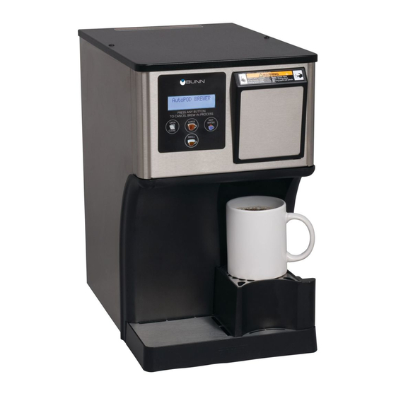
My Café
AP
®
SERVICE & REPAIR MANUAL
BUNN-O-MATIC CORPORATION
POST OFFICE BOX 3227
SPRINGFIELD, ILLINOIS 62708-3227
PHONE: (217) 529-6601
FAX: (217) 529-6644
To ensure you have the latest revision of the Operating Manual, or to view the Illustrated Parts
Catalog, Programming Manual, or Service Manual, please visit the Bunn-O-Matic website, at
www.bunn.com. This is absolutely FREE, and the quickest way to obtain the latest catalog and
manual updates. For Technical Service, contact Bunn-O-Matic Corporation at 1-800-286-6070.
41169.0000A 06/12 ©2012 Bunn-O-Matic Corporation
Advertisement
Chapters
Table of Contents

Related Manuals for Bunn AutoPOD My Cafe AP


Summary of Contents for Bunn AutoPOD My Cafe AP
- Page 1 To ensure you have the latest revision of the Operating Manual, or to view the Illustrated Parts Catalog, Programming Manual, or Service Manual, please visit the Bunn-O-Matic website, at www.bunn.com. This is absolutely FREE, and the quickest way to obtain the latest catalog and manual updates. For Technical Service, contact Bunn-O-Matic Corporation at 1-800-286-6070.
-
Page 2: Warranty
AS SPECIFIED HEREIN, TO REPAIR, REPLACEMENT OR REFUND. In no event shall BUNN be liable for any other damage or loss, including, but not limited to, lost profits, lost sales, loss of use of equipment, claims of Buyer’s customers, cost of capital, cost of down time, cost of substitute equipment, facilities or services, or any other special, incidental or consequential damages. -
Page 3: Table Of Contents
CONTENTS Warranty....................2 Contents ....................3 Troubleshooting .................. 4 Diagnostics ..................9 Service ....................10 Schematics ..................25 Page 3 41169 120711... -
Page 4: Troubleshooting
TROUBLESHOOTING A troubleshooting guide is provided to suggest probable causes and remedies for the most likely problems encountered. If the problem remains after exhausting the troubleshooting steps, contact the Bunn-O-Matic Technical Service Department. • Inspection, testing, and repair of electrical equipment should be performed only by qualified service person- nel. - Page 5 TROUBLESHOOTING (cont.) REFILL CIRCUIT PROBLEM PROBABLE CAUSE REMEDY Make sure water is ON. "FILL TIME TOO LONG" 1. Water shut off Clean out debris. 2. Debris blocking inlet. Contact plumber. 3. Water pressure below 20psi. Check wiring/CBA. 4. No voltage to solenoid valve. Replace solenoid valve.
- Page 6 TROUBLESHOOTING (cont.) HEATING CIRCUIT PROBLEM PROBABLE CAUSE REMEDY "BREW TEMP SENSOR 1. CBA senses open or short circuit. Check wiring. OUT OF RANGE" "BREW TANK 1. Limit Thermostat or TCO open. Replace. HEATING TOO LONG" 2. Tank heater defective. Replace heater. 3.
- Page 7 TROUBLESHOOTING (cont.) BREWING CIRCUIT PROBLEM PROBABLE CAUSE REMEDY Brew cycle will not start 1. Displays error message Brewer has shut down due to mal- function. 2. No power or incorrect voltage to Check for correct voltage at the the brewer. outlet.
- Page 8 TROUBLESHOOTING (cont.) BREWING CIRCUIT (cont.) PROBLEM PROBABLE CAUSE REMEDY "WATER PUMP FAULT 1. Sprayhead blockage. Check/replace. CHECK WATER PUMP" Water does not drop below level probe 2. Tubing between tank and spray- Check/replace. for 90 seconds during brew cycle. head blocked/limed up. 3.
-
Page 9: Diagnostics
TROUBLESHOOTING (cont.) MISCELLANEOUS PROBLEM PROBABLE CAUSE REMEDY "INDEX MOTOR FAULT" 1. Pod(s) binding pod holder as- Remove blockage. CBA has sensed that motor as- sembly. sembly has not rotated timing disk within 15 seconds. 2. Debris on sensor blocking optical Clean. -
Page 10: Service
COMPONENT ACCESS This section provides procedures for testing and replacing various major components used in this brewer should service become necessary. Refer to Troubleshooting for assistance in determining the cause of any problem. WARNING - Inspection, testing, and repair of electri- cal equipment should be performed only by qualified service personnel. -
Page 11: Control Board
CONTROL BOARD FIG. 11-1 CONTROL BOARD - AutoPod FIG. 11-2 CONTROL BOARD - MyCafé AP Location: PRGM LOCK The Control Board is located inside the back cover. 1 2 3 4 6 5 4 3 2 1 Test Procedures: The test procedures for the control board will vary depending upon the problem. -
Page 12: Inlet Valve
INLET VALVE Disconnect the brewer from the power source. Remove the valve and inspect for blockage, and de-lime all related areas. 4. Connect the voltmeter leads to the coil terminals. Turn on the valve with the test mode. Set the meter to AC volts. The indication should be line voltage when activated. -
Page 13: Tanks
TANKS Location: The tanks are located inside the back access panel. AutoPod tanks are not serviceable. NOTE: TANK HEATERS Test Procedures: 1. With a voltmeter, check voltage across the white wire (120V Models) or red wire (120/208-240V Models) from the terminal block and black wire from the control board. -
Page 14: Temperature Probe
TEMPERATURE PROBE If resistance is to specification, replace the control board. If resistance is not to specification, replace the tem- perature probe. Removal and Replacement: 1. Disconnect the brewer from the power source. 2. Disconnect the two pin connector from control board. -
Page 15: Vent Valve
VENT VALVE FIG. 15-1 VENT VALVE - MyCafé AP FIG. 15-2 VENT VALVE - AutoPod Location: The vent valve is located inside the back access panel. Function: The vent valve closes (activates) only during hot water dispense to pressurize tank. Test Procedures: 1. -
Page 16: Air Pumps
AIR PUMPS If resistance is to specification, replace the control board. If resistance is not to specification, replace the motor. Removal and Replacement: 1. Disconnect the brewer from the power source. 2. Disconnect the two pin connector for motor. 3. Remove screw securing motor clamp. 4. -
Page 17: Water Pumps
WATER PUMP FIG. 17-1 WATER PUMP - MyCafé AP FIG. 17-2 WATER PUMP - AutoPod Location: The vent valve is located inside the back access panel. Function: The water pump (boost)on AutoPod pressurizes the brew tank during brew cycle. The water pump on My- Cafe AP pressurizes the sprayhead during brew cycle. -
Page 18: Flow Meter
FLOW METER FIG. 18-2 FLOW METER - AutoPod FIG. 18-1 FLOW METER - MyCafé AP Location: Removal and Replacement: MyCafe-AP: Below main CBA. AutoPod: Behind main CBA. 1. Disconnect the brewer from the power source. Function: 2. Remove back panel. A: Monitors incoming water flow rate (counts pulses). -
Page 19: Ejector Assembly
EJECTOR ASSEMBLY 1. With a voltmeter, check voltage across the terminals of the motor. Activate motor in the "TEST OUTPUTS" program mode. The indication must be 12 vdc on all models. Continuity is not a viable test for this motor. FIG. - Page 20 EJECTOR ASSEMBLY INDEX L MOTOR DUMP NEXT LOAD FIG 19-1b FIG 19-1a UNBLOCKED LOAD POSITION INDEX B MOTOR DUMP NEXT LOAD FIG 19-2b FIG 19-2a UNBLOCKED HOME POSITION INDEX D MOTOR DUMP NEXT LOAD 19-3b FIG 19-3aBLOCKED DUMP POSITION CONTINUED Page 20 41169 120711...
- Page 21 INDEX MOTOR & SENSOR Ejector Assembly: Removal and Replacement: AutoPod & MyCafé-AP 1. Unplug brewer. 2. Remove drip tray and bin assemblies. 3. Remove top cover and rear panel. 4. Pull out on bottom of door bezel. Slide bezel up and off of door.
- Page 22 EJECTOR ASSEMBLY Index Motor Assembly: Removal and Replacement: MyCafé-AP ONLY 1. Press "OPEN/CLOSE" button to open pod door. If you can not operate motor assembly, then manu- ally move pod holder assembly out to the load position. 2. Unplug brewer. 3.
- Page 23 EJECTOR ASSEMBLY Installation: 1. Connect motor and sensor harness to the new motor assembly. 2. Connect brewer to power source. Press "OPEN/ CLOSE" button to open pod door. (or use the "TEST OUTPUTS" to move it to "LOAD POSITION"). 3. Unplug brewer. 4.
- Page 24 EJECTOR ASSEMBLY Check valve replacement: All models 5. If check valve pulls apart, remove remaining 1. Connect brewer to power source. Use the “TEST piece with a spring hook or dental pick. OUTPUTS/TEST INDEX MOTOR” to move it to 6. Install new check valve with O-ring end in first. “DUMP POSITION”.
-
Page 25: Schematics
(GND) HEATER BREW (+12V) BLU/BLK PUMP 120V AC Earth Ground 2 WIRE + GND 120VAC 120VDC SINGLE PHASE POWER CORD FILL BREW Chassis Ground SOLENOID PUMP 41164.0002A 11/10 ©2010 BUNN-O-MATIC CORPORATION Page 25 41169 120711 White Strip-Tac Plus Black Ink... - Page 26 (BLK) PUMP Earth Ground 120V AC 2 WIRE + GND BREW SINGLE PHASE POWER CORD 120VAC FILL SOLENOIDS Chassis Ground 41164.0000B 03/09 ©2008 BUNN-O-MATIC CORPORATION White Strip-Tac Plus Black Ink Finished Size: 5.0" x 7.0" ~58% Page 26 41169 120711...
- Page 27 (BLK) PUMP BREW 230VAC FILL SOLENOIDS FILTER 230V AC 2 WIRE + GND 2.2µF SINGLE PHASE CAPACITOR SHIELDED POWER CORD FERRITE CHOKE Chassis Ground 41164.0001A 09/09 ©2009 BUNN-O-MATIC CORPORATION Page 27 41169 120711 NOT A PURCHASED SCHEMATIC FOR REFERENCE ONLY...