Table of Contents
Advertisement
Quick Links
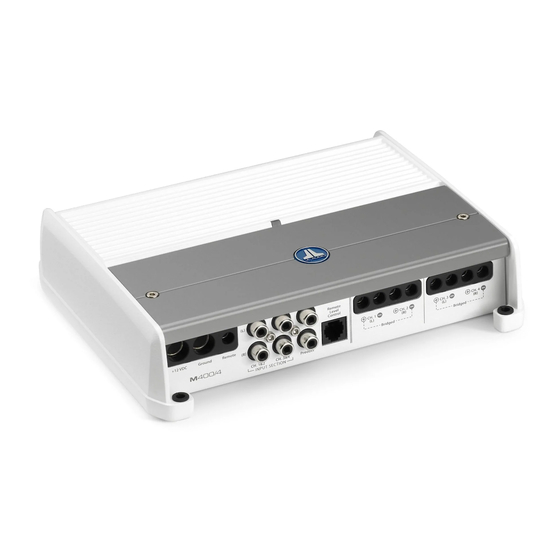
OWNER'S MANUAL
400W Marine 4 Channel Ampli er
NOT FOR USE IN 12 V SYSTEMS!
Thank you for purchasing a JL Audio amplifier for
Your amplifier has been designed and manufactured to exacting
standards in order to ensure years of musical enjoyment in your vessel or
vehicle. For maximum performance, we highly recommend that you have
your new amplifier installed by an authorized JL Audio dealer. Your
authorized dealer has the training, expertise and installation equipment
to ensure optimum performance from this product. Should you
decide to install the amplifier yourself, please take the time
to read this manual thoroughly so as to familiarize yourself
with its installation requirements and setup procedures.
If you have any questions regarding the instructions in this
manual or any aspect of your amplifier's operation, please contact your
authorized JL Audio dealer for assistance. If you need further assistance,
please call the JL Audio Technical Support Department
at (954) 443-1100 during business hours.
your marine sound system.
Advertisement
Table of Contents

Related Manuals for JL Audio M400/4-24V


Summary of Contents for JL Audio M400/4-24V
- Page 1 For maximum performance, we highly recommend that you have your new amplifier installed by an authorized JL Audio dealer. Your authorized dealer has the training, expertise and installation equipment to ensure optimum performance from this product.
-
Page 2: Protect Your Hearing
(pg. 6) (pg. 9) (pg. 11) (pg. 8) (pg. 8) (pg. 8) (pg. 8) Ch. 1 & 2 Input Ch. 3 & 4 Input Sensitivity Control Sensitivity Control (pg. 7) (pg. 7) 2 | JL Audio - M400/4-24V Owner’s Manual... -
Page 3: Planning Your Installation
Cooling Efficiency Considerations: amplifier using appropriate hardware so that it The outer shell of your JL Audio amplifier is does not come loose in the event of a collision or a designed to remove heat from the amplifier sudden jolt to the vehicle or vessel. -
Page 4: Product Description
A fuse near deliver outstanding fidelity and efficiency. the amplifier is not necessary if the The M400/4-24V can be operated with a wide M400/4-24V is the only device being variety of source units and system configurations. -
Page 5: Power Connections
If main power wire (depending on the overall only the M400/4-24V is being run from that current demands of all the amplifiers in the power wire, we recommend a 20A fuse or circuit system). -
Page 6: Turn On Lead
If you wish to send four discrete channels into AWG wire. To connect the remote turn-on the M400/4-24V, simply use all four inputs and set the “Input Mode” switch in the “4 Ch.” position. wire to the amplifier, first back out the set... -
Page 7: Input Sensitivity Controls
INPUT SENSITIVITY CONTROLS The controls labeled “Input Sens.” located in each channel section can be used to match the source unit’s output voltage to the input stage of each pair of amplifier channels for maximum clean output. Rotating the control clockwise will result in higher sensitivity (louder for a given input voltage). -
Page 8: Filter Controls
Filtering between subwoofer systems or more of the M400/4-24V’s channel pairs in a and satellite speaker systems is best done with bi-amplified system. “HP” (High-Pass): Configures the filter to active filters, which cut off frequency content at the input to the amplifier. -
Page 9: Remote Level Control Optional
“Remote Level Control” on the Connection Panel preamp output will change accordingly. 2) “Sum”: When the M400/4-24V is being used of the amplifier using a standard telephone cable (supplied with the HD-RLC). If desired, multiple... -
Page 10: Speaker Outputs
RCA inputs. This option is useful when using a pair of the M400/4-24V’s channels to drive left BRIDGING CONSIDERATIONS channel speakers only and the other pair of the Bridging is the practice of combining the M400/4-24V’s channels to drive right channel... - Page 11 JL Audio dealer so that it may be sent in to JL Audio for service. 3) Constant Red: Indicates that the There are no user serviceable parts or fuses inside amplifier has exceeded its safe operating the amplifier.
-
Page 12: System Configurations
Mode” switch and an appropriate “Filter Freq.” channels will be determined by the M400/4- (80 Hz is a good starting point). 24V’s “Input Sens.” settings and will not be user adjustable from the helm. 12 | JL Audio - M400/4-24V Owner’s Manual... -
Page 13: Multi Amplifier Systems
“CH 1 (Left)” and “CH 2 (Right)” inputs M400/4-24V, it is easy to configure many of the M400/4-24V (select “2 Ch.” on the different multi-amplifier systems. The most common type involves the addition “Input Mode”... - Page 14 APPENDIX A: 9) Once you have adjusted the M400/4-24V to Input Sensitivity Level Setting Following the directions below will allow its maximum low-distortion output level, reconnect the speaker(s). The “Input Sens.” the installer to adjust the input sensitivity of each amplifier channel pair simply...
-
Page 15: General Specifications
APPENDIX B: APPENDIX C: Precise Frequency Selection Chart M400/4-24V Specifications “FILTER FREQ” General Specifications: Detent Panel Actual Recommended Fuse Value: 20A Number Marking Freq. Recommended Fuse Type: MAXI® or AGU Full counter-clockwise: 49 01 ......49 02 . -
Page 16: Appendix D: Troubleshooting
Check the input connectors to ensure that they all are making good contact with the input jacks on the amplifier. 16 | JL Audio - M400/4-24V Owner’s Manual... - Page 17 “My amplifier shuts off once in a while, usually at higher volumes.” Check your voltage source and grounding point. The power supply of the M400/4-24V will operate with charging system voltages down to 20V. Shutdown problems at higher volume levels can occur when the charging system voltage (or remote turn-on voltage) momentarily drops below 20V.
-
Page 18: Installation Notes
INSTALLATION NOTES: Use this diagram to document your amplifier’s switch and control positions. 18 | JL Audio - M400/4-24V Owner’s Manual... - Page 20 All warranty returns should be sent to JL AUDIO ’s Amplifier Service Facility freight-prepaid through an authorized JL AUDIO dealer and must be accompanied by proof of purchase (a copy of the original sales receipt). Direct returns from consumers or non-authorized dealers will be refused unless specifically authorized by JL AUDIO with a valid return authorization number.