ZyXEL Communications GS-3012F User Manual
Gigabit ethernet switch
Hide thumbs
Also See for GS-3012F:
- User manual (235 pages) ,
- Release note (25 pages) ,
- Declaration of conformity (1 page)

Related Manuals for ZyXEL Communications GS-3012F


Summary of Contents for ZyXEL Communications GS-3012F
- Page 1 GS-3012/GS-3012F Gigabit Ethernet Switch User’s Guide Version 3.60 (ABM.4, ABN.5) 3/2006 Edition 2...
-
Page 2: Copyright
ZyXEL Communications Corporation. Published by ZyXEL Communications Corporation. All rights reserved. Disclaimer ZyXEL does not assume any liability arising out of the application or use of any products, or software described herein. -
Page 3: Interference Statements And Warnings
GS-3012/GS-3012F User’s Guide Interference Statements and Warnings FCC Statement This switch complies with Part 15 of the FCC rules. Operation is subject to the following two conditions: 1 This switch may not cause harmful interference. 2 This switch must accept any interference received, including interference that may cause undesired operations. - Page 4 GS-3012/GS-3012F User’s Guide Certifications 1 Go to www.zyxel.com 2 Select your product from the drop-down list box on the ZyXEL home page to go to that product's page. 3 Select the certification you wish to view from this page. Registration Register your product online for free future product updates and information at www.zyxel.com for global products, or at www.us.zyxel.com for North American products.
-
Page 5: Zyxel Limited Warranty
GS-3012/GS-3012F User’s Guide ZyXEL Limited Warranty ZyXEL warrants to the original end user (purchaser) that this product is free from any defects in materials or workmanship for a period of up to two years from the date of purchase. During the warranty period, and... -
Page 6: Customer Support
GS-3012/GS-3012F User’s Guide Customer Support Please have the following information ready when you contact customer support. • Product model and serial number. • Warranty Information. • Date that you received your device. • Brief description of the problem and the steps you took to solve it. - Page 7 GS-3012/GS-3012F User’s Guide METHOD SUPPORT E-MAIL TELEPHONE* WEB SITE REGULAR MAIL SALES E-MAIL FTP SITE LOCATION info@pl.zyxel.com +48 (22) 333 8250 www.pl.zyxel.com ZyXEL Communications ul. Okrzei 1A POLAND +48 (22) 333 8251 03-715 Warszawa Poland http://zyxel.ru/support +7-095-542-89-29 www.zyxel.ru ZyXEL Russia Ostrovityanova 37a Str.
-
Page 8: Table Of Contents
GS-3012/GS-3012F User’s Guide Table of Contents Copyright ........................2 Interference Statements and Warnings..............3 ZyXEL Limited Warranty ..................5 Customer Support ....................6 Table of Contents ..................... 8 List of Figures ......................18 List of Tables ......................22 Preface ........................26 Chapter 1 Getting to Know Your Switch................ - Page 9 GS-3012/GS-3012F User’s Guide Chapter 3 Hardware Overview....................41 3.1 Safety Warnings ....................41 3.2 Front Panel ....................... 41 3.2.1 Console Port .................... 42 3.2.2 Gigabit Ports ................... 43 3.2.2.1 Default Ethernet Negotiation Settings ..........43 3.2.2.2 Auto-crossover ................43 3.2.3 Mini GBIC Slots ..................44 3.2.3.1 Transceiver Installation ..............
- Page 10 GS-3012/GS-3012F User’s Guide Chapter 7 VLAN ........................70 7.1 Introduction to IEEE 802.1Q Tagged VLAN ............70 7.1.1 Forwarding Tagged and Untagged Frames ..........70 7.1.2 Automatic VLAN Registration ..............71 7.1.2.1 GARP .................... 71 7.1.2.2 GARP Timers .................. 71 7.1.2.3 GVRP .....................
- Page 11 GS-3012/GS-3012F User’s Guide Chapter 12 Broadcast Storm Control ..................91 12.1 Introducing Broadcast Storm Control .............. 91 12.2 Configuring Broadcast Storm Control .............. 91 Chapter 13 Mirroring ......................... 93 13.1 Introduction to Port Mirroring ................93 13.2 Port Mirroring Configuration ................93 Chapter 14 Link Aggregation ....................
- Page 12 GS-3012/GS-3012F User’s Guide 17.6.1 Requirements for Using SSH ..............111 17.7 Introduction to HTTPS ..................111 17.7.1 HTTPS Example .................. 112 17.7.2 Internet Explorer Warning Messages ........... 112 17.7.3 Netscape Navigator Warning Messages ..........113 17.7.4 Login Screen ..................113 17.8 Service Access Control ................. 115 17.9 Remote Management ..................
- Page 13 GS-3012/GS-3012F User’s Guide 21.5.2 MVR Modes ..................136 21.5.3 How MVR Works .................. 136 21.6 General MVR Configuration ................. 137 21.7 MVR Group Configuration ................138 21.7.1 MVR Configuration Example ..............140 Chapter 22 DHCP Relay ......................142 22.1 DHCP Relay Overview .................. 142 22.1.1 DHCP “Relay Agent Information Option”...
- Page 14 GS-3012/GS-3012F User’s Guide Chapter 27 Cluster Management.................... 156 27.1 Introduction to Cluster Management ............. 156 27.2 Cluster Management Status ................157 27.2.1 Cluster Member Switch Management ..........158 27.2.1.1 Uploading Firmware to a Cluster Member Switch ...... 158 27.3 Configuring Cluster Management ..............159 Chapter 28 MAC Table......................
- Page 15 GS-3012/GS-3012F User’s Guide 30.9.6 mvr Commands ..................191 Chapter 31 Command Examples.................... 193 31.1 Overview ......................193 31.2 show Commands ................... 193 31.2.1 show system-information ..............193 31.2.2 show hardware-monitor ................ 194 31.2.3 show ip ....................194 31.2.4 show logging ..................195 31.2.5 show interface ..................
- Page 16 GS-3012/GS-3012F User’s Guide Chapter 32 IEEE 802.1Q Tagged VLAN Commands ............. 212 32.1 IEEE 802.1Q Tagged VLAN Overview ............212 32.2 VLAN Databases ................... 212 32.2.1 Static Entries (SVLAN Table) ............... 212 32.2.2 Dynamic Entries (DVLAN Table) ............213 32.3 Configuring Tagged VLAN ................213 32.4 Global VLAN1Q Tagged VLAN Configuration Commands ......
- Page 17 GS-3012/GS-3012F User’s Guide Table of Contents...
-
Page 18: List Of Figures
Figure 8 Mounting the Switch on a Rack .............. 40 Figure 9 Front Panel: GS-3012 ................41 Figure 10 Front Panel: GS-3012F ................. 42 Figure 11 Transceiver Installation Example ............44 Figure 12 Connecting the Fiber Optic Cables ............44 Figure 13 Removing the Fiber Optic Cables ............ - Page 19 GS-3012/GS-3012F User’s Guide Figure 39 Static MAC Forwarding: Summary Table ..........81 Figure 40 Filtering ....................82 Figure 41 Filtering: Summary Table ............... 83 Figure 42 Spanning Tree Protocol: Status ............. 86 Figure 43 Spanning Tree Protocol: Configuration ..........87 Figure 44 Bandwidth Control .................
- Page 20 GS-3012/GS-3012F User’s Guide Figure 82 MVR Group Configuration ..............139 Figure 83 MVR Configuration Example ..............140 Figure 84 MVR Configuration Example ..............140 Figure 85 MVR Configuration Example ..............141 Figure 86 MVR Configuration Example ..............141 Figure 87 DHCP Relay ..................143 Figure 88 Static Routing ..................
- Page 21 GS-3012/GS-3012F User’s Guide Figure 125 CLI: Backup Configuration Example ........... 199 Figure 126 CLI: Restore Configuration Example ........... 200 Figure 127 boot config Command Example ............200 Figure 128 CLI: reload config Command Example ..........200 Figure 129 CLI: Reset to the Factory Default Example ......... 201 Figure 130 no mirror-port Command Example ............
-
Page 22: List Of Tables
GS-3012/GS-3012F User’s Guide List of Tables Table 1 Front Panel Connections ................42 Table 2 Front Panel LED Descriptions ..............46 Table 3 Navigation Panel Sub-links Overview ............49 Table 4 Web Configurator Screen Sub-links Details ..........50 Table 5 Navigation Panel Sub-link Descriptions ............ 50 Table 6 Status ...................... - Page 23 GS-3012/GS-3012F User’s Guide Table 39 SNMP Traps .................... 107 Table 40 Access Control: SNMP ................108 Table 41 Access Control: Logins ................109 Table 42 Access Control: Service Access Control ..........115 Table 43 Access Control: Remote Management ........... 116 Table 44 Physical Queue Priority ................
- Page 24 GS-3012/GS-3012F User’s Guide Table 82 Performance and Management Specifications ........233 Table 83 Physical and Environmental Specifications ..........234 Table 84 Classes of IP Addresses ................. 236 Table 85 Allowed IP Address Range By Class ............237 Table 86 “Natural” Masks ..................237 Table 87 Alternative Subnet Mask Notation ............
- Page 25 GS-3012/GS-3012F User’s Guide List of Tables...
-
Page 26: Preface
-48 VDC to -60 VDC, 1.84A Max. The GS-3012 AC model requires 100~240VAC/1.5A power. About the GS-3012F There are two GS-3012F models. The GS-3012F DC model requires DC power supply input of -48 VDC to -60 VDC, 1.2A Max. The GS-3012F AC model requires 100~240VAC/1.5A power. -
Page 27: Related Documentation
• “e.g.” is a shorthand for “for instance”, and “i.e.” means “that is” or “in other words”. • This User’s Guide will refer to both the GS-3012 and the GS-3012F as the “GS” or “the switch” in this User’s Guide. Distinctions between the models will be made where needed. -
Page 28: User Guide Feedback
Help us help you. E-mail all User Guide-related comments, questions or suggestions for improvement to techwriters@zyxel.com.tw or send regular mail to The Technical Writing Team, ZyXEL Communications Corp., 6 Innovation Road II, Science-Based Industrial Park, Hsinchu, 300, Taiwan. Thank you. Preface... - Page 29 GS-3012/GS-3012F User’s Guide Preface...
-
Page 30: Getting To Know Your Switch
The GS-3012 DC model requires DC power supply input of -48 VDC to -60 VDC, 1.88A Max. The GS-3012F DC model requires DC power supply input of -48 VDC to -60 VDC, 1.2A Max. 12 Gigabit Ports (with two paired with the mini GBIC ports) - GS-3012 Connect up to 12 computers or switches directly to the 100/1000Mbps auto-negotiating, automatic cable sensing (auto-MDIX) Gigabit ports. -
Page 31: Firmware Features
These are slots for mini GBIC (Gigabit Interface Converter) transceivers. These allow the GS to connect to another WAN switch or daisy-chain to other switches. Four 100/1000 Mbps Gigabit Ports (paired with mini GBIC ports) - GS-3012F Connect up to four computers or switches directly to the 100/1000Mbps auto-negotiating, automatic cable sensing (auto-MDIX) Gigabit ports. -
Page 32: System Monitoring
GS-3012/GS-3012F User’s Guide • Bridge extension MIBs RFC 2674 • Interface MIB RFC 2863 • Ping and Trace Route RFC 2925 Management • Web configurator • Command-line interface locally via console port or remotely via Telnet • Out-of-band RJ-45 management port •... -
Page 33: Applications
GS-3012/GS-3012F User’s Guide STP (Spanning Tree Protocol) / RSTP (Rapid STP) (R)STP detects and breaks network loops and provides backup links between switches, bridges or routers. It allows a switch to interact with other (R)STP -compliant switches in your network to ensure that only one path exists between any two stations on the network. -
Page 34: Bridging Example
GS-3012/GS-3012F User’s Guide 1.3.2 Bridging Example In this example application the switch is the ideal solution for different company departments to connect to the corporate backbone. It can alleviate bandwidth contention and eliminate server and network bottlenecks. All users that need high bandwidth can connect to high-speed department servers via the switch. -
Page 35: Ieee 802.1Q Vlan Application Examples
GS-3012/GS-3012F User’s Guide Figure 3 High Performance Switched Application 1.3.4 IEEE 802.1Q VLAN Application Examples This section shows a workgroup and a shared server example using 802.1Q tagged VLANs. For more information on VLANs, see the Switch Setup section and the VLAN Setup chapter in this User’s Guide. -
Page 36: Vlan Shared Server Example
GS-3012/GS-3012F User’s Guide 1.3.4.2 VLAN Shared Server Example Shared resources such as a server can be used by all ports in the same VLAN as the server, as shown in the following example. In this example, only ports that need access to the server need belong to VLAN 1 while they can belong to other VLAN groups too. - Page 37 GS-3012/GS-3012F User’s Guide Chapter 1 Getting to Know Your Switch...
-
Page 38: Chapter 2 Hardware Installation And Connection
GS-3012/GS-3012F User’s Guide H A P T E R Hardware Installation and Connection This chapter shows you how to install and connect the switch. 2.1 Installation Scenarios The switch can be placed on a desktop or rack-mounted on a standard EIA rack. Use the rubber feet in a desktop installation and the brackets in a rack-mounted installation. -
Page 39: Mounting The Switch On A Rack
GS-3012/GS-3012F User’s Guide Figure 6 Attaching Rubber Feet Note: Do NOT block the ventilation holes. Leave space between devices when stacking. 2.3 Mounting the Switch on a Rack The switch can be mounted on an EIA standard size, 19-inch rack or in a wiring closet with other equipment. -
Page 40: Mounting The Switch On A Rack
GS-3012/GS-3012F User’s Guide Figure 7 Attaching the Mounting Brackets 2 Using a #2 Philips screwdriver, install the M3 flat head screws through the mounting bracket holes into the switch. 3 Repeat steps to install the second mounting bracket on the other side of the switch. -
Page 41: Chapter 3 Hardware Overview
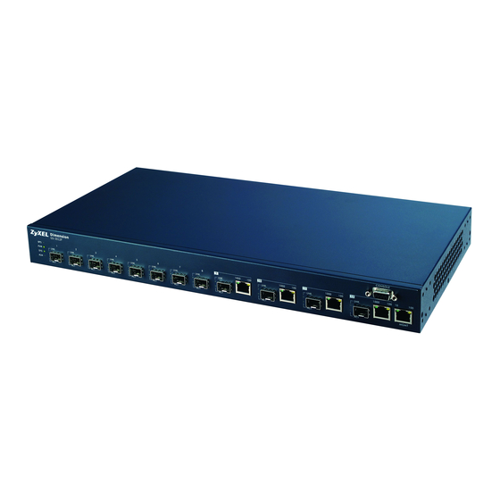
Ethernet Ports Mini-GBIC Ports Management Port The following figure shows the front panel of the GS-3012F. The front panel contains the switch LEDs, 12 mini GBIC ports, four RJ-45 Gigabit ports, and a console and management port for local management. -
Page 42: Console Port
• No parity, 8 data bits, 1 stop bit • No flow control Connect the male 9-pin end of the console cable to the console port of the GS-3012F switch. Connect the female end to a serial port (COM1, COM2 or other COM port) of your computer. -
Page 43: Gigabit Ports
Gigabit ports can be 100Mbps or 1000Mbps and the duplex mode can be half duplex (at 100 Mbps) or full duplex. The GS-3012F’s Gigabit ports are paired with mini GBIC slots. The switch uses up to one connection for each mini GBIC and Gigabit pair. The mini GBIC ports have priority over the Gigabit ports. -
Page 44: Mini Gbic Slots
GS-3012/GS-3012F User’s Guide 3.2.3 Mini GBIC Slots These are slots for mini GBIC (Gigabit Interface Converter) transceivers. A transceiver is a single unit that houses a transmitter and a receiver. The GS does not come with transceivers. You must use transceivers that comply with the Small Form-factor Pluggable (SFP) Transceiver MultiSource Agreement (MSA). -
Page 45: Management Port
GS-3012/GS-3012F User’s Guide 1 Remove the fiber optic cables from the transceiver. 2 Open the transceiver’s latch (latch styles vary). 3 Pull the transceiver out of the slot. Figure 13 Removing the Fiber Optic Cables Figure 14 Opening the Transceiver’s Latch Example Figure 15 Transceiver Removal Example 3.2.4 Management Port... -
Page 46: Power Connector
The DC power model requires DC power supply input of –48 VDC to -60 VDC. The GS-3012 DC power model requires 1.88A Max. The GS-3012F requires 1.2A Max. To connect the power to the unit, insert the one end of the supplied power cord to the power receptacle on the rear panel and the other end to a power outlet. -
Page 47: Configuring The Switch
GS-3012/GS-3012F User’s Guide Table 2 Front Panel LED Descriptions (continued) COLOR STATUS DESCRIPTION LNK/ACT Green Blinking The system is transmitting/receiving to/from an Ethernet network. (GS- The link to a 1000 Mbps Ethernet network is up. 3012) Amber Blinking The system is transmitting/receiving to/from an Ethernet network. -
Page 48: Introducing The Web Configurator
GS-3012/GS-3012F User’s Guide H A P T E R Introducing the Web Configurator This section introduces the configuration and functions of the web configurator. 4.1 Introduction The embedded web configurator allows you to manage the switch from anywhere through a standard browser such as Microsoft Internet Explorer or Netscape Navigator. -
Page 49: Status Screen
GS-3012/GS-3012F User’s Guide 4.3 Status Screen The Status screen is the first web configurator screen you see after you log in. The following figure shows the navigating components of a web configurator screen. Figure 18 Web Configurator Home Screen (Status) In the navigation panel, click a main link to reveal a list of submenu links. -
Page 50: Table 4 Web Configurator Screen Sub-Links Details
GS-3012/GS-3012F User’s Guide The following table lists the various web configurator screens within the sub-links. Table 4 Web Configurator Screen Sub-links Details ADVANCED BASIC SETTING ROUTING PROTOCOL MANAGEMENT APPLICATION System Info VLAN Status Static Routing Maintenance General Setup VLAN Port Setting... - Page 51 GS-3012/GS-3012F User’s Guide Table 5 Navigation Panel Sub-link Descriptions (continued) LABEL DESCRIPTION General Setup This link takes you to a screen where you can configure general identification information about the switch. Switch Setup This link takes you to a screen where you can set up global switch parameters such as VLAN type, MAC address learning, IGMP snooping, GARP and priority queues.
-
Page 52: Change Your Password
GS-3012/GS-3012F User’s Guide Table 5 Navigation Panel Sub-link Descriptions (continued) LABEL DESCRIPTION Maintenance This link takes you to screens where you can perform firmware and configuration file maintenance as well as reboot the system. Diagnostic This link takes you to screens where you can view system logs and test port(s). -
Page 53: Resetting The Switch
GS-3012/GS-3012F User’s Guide 2 Deleting all port-based VLANs with the CPU port as a member. The “CPU port” is the management port of the switch. 3 Filtering all traffic to the CPU port. 4 Disabling all ports. 5 Assigning minimum bandwidth to the CPU port. If you limit bandwidth to the CPU port, you may find that the switch performs sluggishly or not at all. -
Page 54: Logging Out Of The Web Configurator
GS-3012/GS-3012F User’s Guide Figure 20 Resetting the Switch: Via Console Port Bootbase Version: V1.0 | 04/25/2003 10:01:06 RAM: Size = 32768 Kbytes FLASH: Intel 32M ZyNOS Version: V3.60(ABN.5)| 03/01/2006 09:53:18 Press any key to enter debug mode within 3 seconds. -
Page 55: System Status And Port Details
GS-3012/GS-3012F User’s Guide H A P T E R System Status and Port Details This chapter describes the system status (web configurator home page) and port details screens. 5.1 About System Statistics and Information The home screen of the web configurator displays a port statistical summary with links to each port showing statistical details. -
Page 56: Port Details
GS-3012/GS-3012F User’s Guide The following table describes the labels in this screen. Table 6 Status LABEL DESCRIPTION System up This field shows how long the system has been running since the last time it was Time started. Port This identifies the Gigabit port. Click a port number to display the Port Details screen... -
Page 57: Figure 23 Status: Port Details
GS-3012/GS-3012F User’s Guide Figure 23 Status: Port Details The following table describes the labels in this screen. Table 7 Status: Port Details LABEL DESCRIPTION Port Info Port NO. This field identifies the Gigabit port described in this screen. Link This field shows whether the port connection is down, and the speed/duplex mode. - Page 58 GS-3012/GS-3012F User’s Guide Table 7 Status: Port Details (continued) LABEL DESCRIPTION Up Time This field shows the total amount of time the connection has been up. Tx Packet The following fields display detailed information about frames transmitted. TX Packets This field shows the number of good frames (unicast, multicast and broadcast) transmitted.
- Page 59 GS-3012/GS-3012F User’s Guide Table 7 Status: Port Details (continued) LABEL DESCRIPTION 512-1023 This field shows the number of packets (including bad packets) received that were between 512 and 1023 octets in length. 1024-1518 This field shows the number of packets (including bad packets) received that were between 1024 and 1518 octets in length.
-
Page 60: Chapter 6 Basic Setting
GS-3012/GS-3012F User’s Guide H A P T E R Basic Setting This chapter describes how to configure the System Info, General Setup, Switch Setup, IP Setup and Port Setup screens. 6.1 Introducing the Basic Setting Screens The System Info screen displays general switch information (such as firmware version number) and hardware polling information (such as fan speeds). -
Page 61: Figure 24 System Info
GS-3012/GS-3012F User’s Guide Figure 24 System Info The following table describes the labels in this screen. Table 8 System Info LABEL DESCRIPTION System Name This field displays the switch's model name. ZyNOS F/W This field displays the version number of the switch’s current firmware including the Version date created. -
Page 62: General Setup
GS-3012/GS-3012F User’s Guide Table 8 System Info (continued) LABEL DESCRIPTION This field displays this fan's maximum speed measured in Revolutions Per Minute (RPM). This field displays this fan's minimum speed measured in Revolutions Per Minute (RPM). Threshold This field displays the minimum speed at which a normal fan should work. -
Page 63: Table 9 General Setup
GS-3012/GS-3012F User’s Guide The following table describes the labels in this screen. Table 9 General Setup LABEL DESCRIPTION System Name Choose a descriptive name for identification purposes. This name consists of up to 32 printable characters; spaces are allowed. Location Enter the geographic location (up to 32 characters) of your switch. -
Page 64: Introduction To Vlans
GS-3012/GS-3012F User’s Guide 6.4 Introduction to VLANs A VLAN (Virtual Local Area Network) allows a physical network to be partitioned into multiple logical networks. Devices on a logical network belong to one group. A device can belong to more than one group. With VLAN, a device cannot directly talk to or hear from devices that are not in the same group(s);... -
Page 65: Table 10 Switch Setup
GS-3012/GS-3012F User’s Guide The following table describes the labels in this screen. Table 10 Switch Setup LABEL DESCRIPTION VLAN Type Choose 802.1Q or Port Based. The VLAN Setup screen changes depending on whether you choose 802.1Q VLAN Type or Port Based VLAN Type in this screen. -
Page 66: Ip Setup
GS-3012/GS-3012F User’s Guide Table 10 Switch Setup (continued) LABEL DESCRIPTION Level 0 Typically used for best-effort traffic. Apply Click Apply to save your changes back to the switch. Cancel Click Cancel to begin configuring this screen afresh. 6.6 IP Setup Use the IP Setup screen to configure the switch IP address, default gateway device, the default domain name server and the management VLAN ID. -
Page 67: Table 11 Ip Setup
GS-3012/GS-3012F User’s Guide The following table describes the labels in this screen. Table 11 IP Setup LABEL DESCRIPTION Domain Name DNS (Domain Name System) is for mapping a domain name to its Server corresponding IP address and vice versa. Enter a domain name server IP address in order to be able to use a domain name instead of an IP address. -
Page 68: Port Setup
GS-3012/GS-3012F User’s Guide Table 11 IP Setup (continued) LABEL DESCRIPTION IP Subnet Mask Enter the IP subnet mask in dotted decimal notation. Type the VLAN group identification number. Default Gateway Enter the IP address of the default outgoing gateway in dotted decimal notation. -
Page 69: Table 12 Port Setup
GS-3012/GS-3012F User’s Guide The following table describes the fields in this screen. Table 12 Port Setup LABEL DESCRIPTION Port This is the port index number. Active Select this check box to enable a port. The factory default for all ports is enabled. A port must be enabled for data transmission to occur. -
Page 70: Chapter 7 Vlan
GS-3012/GS-3012F User’s Guide H A P T E R VLAN The type of screen you see here depends on the VLAN Type you selected in the Switch Setup screen. This chapter shows you how to configure 802.1Q tagged and port-based VLANs. See the General, Switch and IP Setup chapter for more information. -
Page 71: Automatic Vlan Registration
GS-3012/GS-3012F User’s Guide 7.1.2 Automatic VLAN Registration GARP and GVRP are the protocols used to automatically register VLAN membership across switches. 7.1.2.1 GARP GARP (Generic Attribute Registration Protocol) allows network switches to register and de- register attribute values with other GARP participants within a bridged LAN. GARP is a protocol that provides a generic mechanism for protocols that serve a more specific application, for example, GVRP. -
Page 72: Port Vlan Trunking
GS-3012/GS-3012F User’s Guide 7.1.3 Port VLAN Trunking Enable VLAN Trunking on a port to allow frames belonging to unknown VLAN groups to pass through that port. This is useful if you want to set up VLAN groups on end devices without having to configure the same VLAN groups on intermediary devices. -
Page 73: Figure 31 802.1Q Vlan Status
GS-3012/GS-3012F User’s Guide Figure 31 802.1Q VLAN Status The following table describes the labels in this screen. Table 14 802.1Q VLAN Status LABEL DESCRIPTION The Number of This is the number of VLANs configured on the switch. VLAN Index This is the VLAN index number. -
Page 74: Q Vlan Port Settings
GS-3012/GS-3012F User’s Guide 7.2.1 802.1Q VLAN Port Settings To configure the 802.1Q VLAN settings on a port, click the VLAN Port Settings link in the VLAN Status screen. Figure 32 802.1Q VLAN Port Settings The following table describes the labels in this screen. -
Page 75: Q Static Vlan
GS-3012/GS-3012F User’s Guide Table 15 802.1Q VLAN Port Settings (continued) LABEL DESCRIPTION Acceptable Specify the type of frames allowed on a port. Choices are All and Tag Only. Frame Type Select All to accept all frames with untagged or tagged frames on this port. This is the default setting. -
Page 76: Viewing And Editing Vlan Settings
GS-3012/GS-3012F User’s Guide The following table describes the labels in this screen. Table 16 802.1Q Static VLAN LABEL DESCRIPTION Active Select this check box to enable the VLAN. Name Enter a descriptive name for this VLAN group for identification purposes. -
Page 77: Vid1 Example Screen
GS-3012/GS-3012F User’s Guide 7.2.3.1 VID1 Example Screen Figure 35 VID1 Example Screen 7.3 Introduction to Port-based VLANs Port-based VLANs are VLANs where the packet forwarding decision is based on the destination MAC address and its associated port. Port-based VLANs require allowed outgoing ports to be defined for each port. Therefore, if... -
Page 78: Figure 36 Port Based Vlan Setup (All Connected)
GS-3012/GS-3012F User’s Guide Figure 36 Port Based VLAN Setup (All Connected) Figure 37 Port Based VLAN Setup (Port isolation) Chapter 7 VLAN... -
Page 79: Table 18 Port Based Vlan Setup
GS-3012/GS-3012F User’s Guide The following table describes the labels in this screen. Table 18 Port Based VLAN Setup LABEL DESCRIPTION Setting Choose from All connected or Port isolation. Wizard All connected means all ports can communicate with each other, that is, there are no virtual LANs. -
Page 80: Static Mac Forward Setup
GS-3012/GS-3012F User’s Guide H A P T E R Static MAC Forward Setup Use these screens to configure static MAC address forwarding. 8.1 Introduction to Static MAC Forward Setup A static MAC address entry is an address that has been manually entered in the MAC address learning table. -
Page 81: Viewing And Editing Static Mac Forwarding Rules
GS-3012/GS-3012F User’s Guide Table 19 Static MAC Forwarding (continued) LABEL DESCRIPTION Enter the MAC address in valid MAC address format, that is, six hexadecimal character Address pairs. Static MAC addresses do not age out. Enter the VLAN identification number. Port Select a port where the MAC address entered in the previous field will be automatically forwarded. -
Page 82: Chapter 9 Filtering
GS-3012/GS-3012F User’s Guide H A P T E R Filtering This chapter discusses static IP and MAC address port filtering. 9.1 Introduction to Filtering Filtering means sifting traffic going through the switch based on the source and/or destination MAC addresses and VLAN group (ID). -
Page 83: Viewing And Editing Filter Rules
GS-3012/GS-3012F User’s Guide Table 21 Filtering (continued) LABEL DESCRIPTION Action Select Discard source to drop frame from the source MAC address (specified in the MAC field). The switch can still send frames to the MAC address. Select Discard destination to drop frames to the destination MAC address (specified in the MAC address). -
Page 84: Chapter 10 Spanning Tree Protocol
GS-3012/GS-3012F User’s Guide H A P T E R Spanning Tree Protocol This chapter introduces the Spanning Tree Protocol (STP). 10.1 Introduction to Spanning Tree Protocol (STP) STP detects and breaks network loops and provides backup links between switches, bridges or routers. -
Page 85: How Stp Works
GS-3012/GS-3012F User’s Guide 10.1.2 How STP Works After a bridge determines the lowest cost-spanning tree with STP, it enables the root port and the ports that are the designated ports for connected LANs, and disables all other ports that participate in STP. Network packets are therefore only forwarded between enabled ports, eliminating any possible network loops. -
Page 86: Figure 42 Spanning Tree Protocol: Status
GS-3012/GS-3012F User’s Guide Figure 42 Spanning Tree Protocol: Status The following table describes the labels in this screen. Table 25 Spanning Tree Protocol: Status LABEL DESCRIPTION Spanning Tree This field displays Running if STP is activated. Otherwise, it displays Down. -
Page 87: Configuring Stp
GS-3012/GS-3012F User’s Guide Table 25 Spanning Tree Protocol: Status (continued) LABEL DESCRIPTION Poll Interval(s) The text box displays how often (in seconds) this screen refreshes. You may change the refresh interval by typing a new number in the text box and then clicking Set Interval. -
Page 88: Table 26 Spanning Tree Protocol: Configuration
GS-3012/GS-3012F User’s Guide The following table describes the labels in this screen. Table 26 Spanning Tree Protocol: Configuration LABEL DESCRIPTION Active Select this check box to activate STP. Bridge Priority Bridge priority is used in determining the root switch, root port and designated port. The switch with the highest priority (lowest numeric value) becomes the STP root switch. -
Page 89: Chapter 11 Bandwidth Control
GS-3012/GS-3012F User’s Guide H A P T E R Bandwidth Control This chapter shows you how you can set the maximum bandwidth allowed for traffic flows on a port using the Bandwidth Control setup screens. 11.1 Introduction to Bandwidth Control Bandwidth control means defining a maximum allowable bandwidth for incoming and/or out- going traffic flows on a port. -
Page 90: Figure 44 Bandwidth Control
GS-3012/GS-3012F User’s Guide Figure 44 Bandwidth Control The following table describes the labels in this screen. Table 27 Bandwidth Control LABEL DESCRIPTION Active Select this check box to activate bandwidth control. Port This field displays the port number. Active Make sure to select this check box to activate your rule. You may temporarily deactivate a rule without deleting it by deselecting this check box. -
Page 91: Broadcast Storm Control
GS-3012/GS-3012F User’s Guide H A P T E R Broadcast Storm Control 12.1 Introducing Broadcast Storm Control Broadcast storm control limits the number of broadcast, multicast and destination lookup failure (DLF) packets the switch receives per second on the ports. When the maximum number of allowable broadcast, multicast and/or DLF packets is reached per second, the subsequent packets are discarded. - Page 92 GS-3012/GS-3012F User’s Guide The following table describes the labels in this screen. Table 28 Broadcast Storm Control LABEL DESCRIPTION Active Select this check box to enable broadcast storm control on the switch. Port This field displays a port number. Broadcas Select this option and specify how many broadcast packets the port receives per second.
-
Page 93: Chapter 13 Mirroring
GS-3012/GS-3012F User’s Guide H A P T E R Mirroring This chapter discusses the Mirror setup screens. 13.1 Introduction to Port Mirroring Port mirroring allows you to copy traffic going from one or all ports to another or all ports in order that you can examine the traffic from the monitor port (the port you copy the traffic to) without interference. -
Page 94: Table 29 Mirroring
GS-3012/GS-3012F User’s Guide The following table describes the related labels in this screen. Table 29 Mirroring LABEL DESCRIPTION Active Clear this check box to deactivate port mirroring on the switch. Monitor The monitor port is the port you copy the traffic to in order to examine it in more detail Port without interfering with the traffic flow on the original port(s). -
Page 95: Chapter 14 Link Aggregation
GS-3012/GS-3012F User’s Guide H A P T E R Link Aggregation This chapter shows you how to logically aggregate physical links to form one logical, higher- bandwidth link. 14.1 Introduction to Link Aggregation Link aggregation (trunking) is the grouping of physical ports into one logical higher-capacity link. -
Page 96: Link Aggregation Id
GS-3012/GS-3012F User’s Guide 14.1.2 Link Aggregation ID LACP aggregation ID consists of the following information: Table 30 Link Aggregation ID: Local Switch SYSTEM PRIORITY MAC ADDRESS PORT PRIORITY PORT NUMBER 0000 00-00-00-00-00 0000 0000 Table 31 Link Aggregation ID: Peer Switch... -
Page 97: Link Aggregation Setup
GS-3012/GS-3012F User’s Guide The following table describes the labels in this screen. Table 32 Link Aggregation: Link Aggregation Protocol Status LABEL DESCRIPTION Index This field displays the trunk ID to identify a trunk group, that is, one logical link containing multiple ports. -
Page 98: Figure 48 Link Aggregation: Configuration
GS-3012/GS-3012F User’s Guide Figure 48 Link Aggregation: Configuration The following table describes the labels in this screen. Table 33 Link Aggregation: Configuration LABEL DESCRIPTION Link Aggregation Control Protocol Active Select this checkbox to enable Link Aggregation Control Protocol (LACP). System Priority LACP system priority is a number between 1 and 65, 535. The switch with the lowest system priority (and lowest port number if system priority is the same) becomes the LACP “server”. - Page 99 GS-3012/GS-3012F User’s Guide Table 33 Link Aggregation: Configuration (continued) LABEL DESCRIPTION LACP Timeout Timeout is the time interval between the individual port exchanges of LACP packets in order to check that the peer port in the trunk group is still up. If a port does not respond after three tries, then it is deemed to be “down”...
-
Page 100: Chapter 15 Port Authentication
GS-3012/GS-3012F User’s Guide H A P T E R Port Authentication This chapter describes the 802.1x authentication method and RADIUS server connection setup. 15.1 Introduction to Authentication IEEE 802.1x is an extended authentication protocol that allows support of RADIUS (Remote Authentication Dial In User Service, RFC 2138, 2139) for centralized user profile management on a network RADIUS server. -
Page 101: Configuring Radius Server Settings
GS-3012/GS-3012F User’s Guide Figure 50 Port Authentication 15.2.1 Configuring RADIUS Server Settings From the Port Authentication screen, click RADIUS to display the configuration screen as shown. Figure 51 Port Authentication: RADIUS The following table describes the labels in this screen. -
Page 102: Figure 52 Port Authentication: 802.1X
GS-3012/GS-3012F User’s Guide Figure 52 Port Authentication: 802.1x The following table describes the labels in this screen. Table 35 Port Authentication: 802.1x LABEL DESCRIPTION Active Select this check box to permit 802.1x authentication on the switch. Note: You must first allow 802.1x authentication on the switch before configuring it on each port. -
Page 103: Chapter 16 Port Security
GS-3012/GS-3012F User’s Guide H A P T E R Port Security This chapter shows you how to set up port security. 16.1 About Port Security Port security allows only packets with dynamically learned MAC addresses and/or configured static MAC addresses to pass through a port on the switch. The switch can learn up to 16K MAC addresses in total with no limit on individual ports other than the sum cannot exceed 16K. -
Page 104: Table 36 Port Security
GS-3012/GS-3012F User’s Guide The following table describes the labels in this screen. Table 36 Port Security LABEL DESCRIPTION Active Select this check box to enable the port security feature on the switch. Port This field displays a port number. Active Select this check box to enable port security on this port. -
Page 105: Chapter 17 Access Control
GS-3012/GS-3012F User’s Guide H A P T E R Access Control This chapter describes how to control access to the switch. 17.1 About Access Control Click Advanced Application, Access Control from the navigation panel to display the screen as shown. From this screen you can configure SNMP, up to four web configurator administrators, enable/disable remote service access and configure trusted computers for remote access. -
Page 106: About Snmp
GS-3012/GS-3012F User’s Guide Figure 55 Console Port Priority “Local administrator is configuring this device now!!! Connection to host lost.” 17.3 About SNMP Simple Network Management Protocol is a protocol used for exchanging management information between network switches. SNMP is a member of TCP/IP protocol suite. A manager station can manage and monitor the switch through the network via SNMP version one (SNMPv1) and/or SNMP version 2c. -
Page 107: Supported Mibs
GS-3012/GS-3012F User’s Guide SNMP itself is a simple request/response protocol based on the manager/agent model. The manager issues a request and the agent returns responses using the following protocol operations: Table 38 SNMP Commands COMMAND DESCRIPTION Allows the manager to retrieve an object variable from the agent. -
Page 108: Configuring Snmp
GS-3012/GS-3012F User’s Guide Table 39 SNMP Traps (continued) OBJECT LABEL OBJECT ID DESCRIPTION authenticationFailure 1.3.6.1.6.3.1.1.5.5 This trap is sent when an SNMP request comes from non- authenticated hosts. RFC 1493 Traps newRoot 1.3.6.1.2.1.17.0.1 This trap is sent when the STP root switch changes. -
Page 109: Figure 58 Access Control: Logins
GS-3012/GS-3012F User’s Guide 1 An administrator is someone who can both view and configure switch changes. The username for the Administrator is always admin. The default administrator password is 1234. Note: It is highly recommended that you change the default administrator password ("1234"). -
Page 110: Ssh Overview
GS-3012/GS-3012F User’s Guide 17.4 SSH Overview Unlike Telnet or FTP, which transmit data in clear text, SSH (Secure Shell) is a secure communication protocol that combines authentication and data encryption to provide secure encrypted communication between two hosts over an unsecured network. -
Page 111: Ssh Implementation
GS-3012/GS-3012F User’s Guide 3 Authentication and Data Transmission After the identification is verified and data encryption activated, a secure tunnel is established between the client and the server. The client then sends its authentication information (user name and password) to the server to log in to the server. -
Page 112: Https Example
GS-3012/GS-3012F User’s Guide Figure 61 HTTPS Implementation Note: If you disable HTTP in the Service Access Control screen, then the switch blocks all HTTP connection attempts. 17.7.1 HTTPS Example If you haven’t changed the default HTTPS port on the switch, then in your browser enter “https:// switch IP Address/”... -
Page 113: Netscape Navigator Warning Messages
GS-3012/GS-3012F User’s Guide 17.7.3 Netscape Navigator Warning Messages When you attempt to access the switch HTTPS server, a Website Certified by an Unknown Authority screen pops up asking if you trust the server certificate. Click Examine Certificate if you want to verify that the certificate is from the switch. -
Page 114: Figure 65 Main Screen (Internet Explorer)
GS-3012/GS-3012F User’s Guide Figure 65 Main Screen (Internet Explorer) Figure 66 Main Screen (Netscape) Chapter 17 Access Control... -
Page 115: Service Access Control
GS-3012/GS-3012F User’s Guide 17.8 Service Access Control Service Access Control allows you to decide what services you may use to access the switch. You may also change the default service port and configure “trusted computer(s)” for each service in the Remote Management screen (discussed later). Click Access Control to go back to the Access Control screen. -
Page 116: Figure 68 Access Control: Remote Management
GS-3012/GS-3012F User’s Guide Figure 68 Access Control: Remote Management The following table describes the labels in this screen. Table 43 Access Control: Remote Management LABEL DESCRIPTION Entry This is the client set index number. A “client set” is a group of one or more “trusted computers”... -
Page 117: Queuing Method
GS-3012/GS-3012F User’s Guide H A P T E R Queuing Method This chapter introduces SPQ and WFQ. 18.1 Introduction to Queuing Queuing is used to help solve performance degradation when there is network congestion. Use the Queuing Method screen to configure queuing algorithms for outgoing traffic. See also Priority Queue Assignment in Switch Setup and 802.1p Priority in Port Setup for related... -
Page 118: Weighted Round Robin Scheduling (Wrr)
GS-3012/GS-3012F User’s Guide 18.1.2 Weighted Round Robin Scheduling (WRR) Round Robin Scheduling services queues on a rotating basis and is activated only when a port has more traffic than it can handle. A queue is given an amount of bandwidth irrespective of the incoming traffic on that port. -
Page 119: Table 45 Queuing Method
GS-3012/GS-3012F User’s Guide The following table describes the labels in this screen. Table 45 Queuing Method LABEL DESCRIPTION Port This label shows the port you are configuring. Method Select SPQ (Strict Priority Queuing) or WRR (Weighted Round Robin Scheduling). Strict Priority Queuing (SPQ) services queues based on priority only. When the highest priority queue empties, traffic on the next highest-priority queue begins. -
Page 120: Chapter 19 Classifier
GS-3012/GS-3012F User’s Guide H A P T E R Classifier This chapter introduces and shows you how to configure the packet classifier on the switch. 19.1 About the Classifier and QoS Quality of Service (QoS) refers to both a network’s ability to deliver data with minimum delay, and the networking methods used to control the use of bandwidth. -
Page 121: Figure 70 Classifier
GS-3012/GS-3012F User’s Guide Figure 70 Classifier The following table describes the labels in this screen. Table 46 Classifier LABEL DESCRIPTION Active Select this option to enable this rule. Name Enter a descriptive name for this rule for identifying purposes. Packet Format Specify the format of the packet. - Page 122 GS-3012/GS-3012F User’s Guide Table 46 Classifier (continued) LABEL DESCRIPTION Ethernet Type Select an Ethernet type or select Others and enter the Ethernet type number in hexadecimal value. Refer to Table 48 on page 123 for information. Source MAC Address Select Any to apply the rule to all MAC addresses.
-
Page 123: Viewing And Editing Classifier Configuration
GS-3012/GS-3012F User’s Guide 19.3 Viewing and Editing Classifier Configuration To view a summary of the classifier configuration, scroll down to the summary table at the bottom of the Classifier screen. To change the settings of a rule, click a number in the Index field. -
Page 124: Classifier Example
GS-3012/GS-3012F User’s Guide Some of the most common IP ports are: Table 49 Common IP Ports PORT NUMBER PORT NAME Telnet SMTP HTTP POP3 19.4 Classifier Example The following figure shows an example where you configure a classifier that identifies all traffic from MAC address 00:50:ba:ad:4f:81 on port 2. -
Page 125: Chapter 20 Policy Rule
GS-3012/GS-3012F User’s Guide H A P T E R Policy Rule This chapter shows you how to configure policy rules. 20.1 About Policy Rules A classifier distinguishes traffic into flows based on the configured criteria (refer to for more information). A policy rule ensures that a traffic flow gets the requested treatment in the network. -
Page 126: Figure 73 Policy
GS-3012/GS-3012F User’s Guide Click Advanced Applications and then Policy Rule in the navigation panel to display the screen as shown. Figure 73 Policy The following table describes the labels in this screen. Table 50 Policy LABEL DESCRIPTION Active Select this option to enable the policy. - Page 127 GS-3012/GS-3012F User’s Guide Table 50 Policy (continued) LABEL DESCRIPTION Classifier(s) This field displays the active classifier(s) you configure in the Classifier screen (refer to Select the classifier(s) to which this policy rule applies. To select more than one classifier, press [SHIFT] and select the choices at the same time.
-
Page 128: Viewing And Editing Policy Configuration
GS-3012/GS-3012F User’s Guide Table 50 Policy (continued) LABEL DESCRIPTION Outgoing Select Send the packet to the mirror port to send the packet to the mirror port. Select Send the packet to the egress port to send the packet to the egress port. -
Page 129: Policy Example
GS-3012/GS-3012F User’s Guide Table 51 Policy: Summary Table (continued) LABEL DESCRIPTION Delete Click Delete to remove the selected entry from the summary table. Cancel Click Cancel to clear the Delete check boxes. 20.4 Policy Example The figure below shows an example Policy screen where you configure a policy to limit... -
Page 130: Figure 75 Policy Example
GS-3012/GS-3012F User’s Guide Figure 75 Policy Example Chapter 20 Policy Rule... -
Page 131: Chapter 21 Multicast
GS-3012/GS-3012F User’s Guide H A P T E R Multicast This chapter shows you how to configure various multicast features. 21.1 Multicast Overview Traditionally, IP packets are transmitted in one of either two ways - Unicast (1 sender to 1 recipient) or Broadcast (1 sender to everybody on the network). -
Page 132: Multicast Status
GS-3012/GS-3012F User’s Guide A switch can passively snoop on IGMP Query, Report and Leave (IGMP version 2) packets transferred between IP multicast routers/switches and IP multicast hosts to learn the IP multicast group membership. It checks IGMP packets passing through it, picks out the group registration information, and configures multicasting accordingly. -
Page 133: Figure 77 Multicast Setting
GS-3012/GS-3012F User’s Guide Figure 77 Multicast Setting The following table describes the labels in this screen. Table 53 Multicast Setting LABEL DESCRIPTION IGMP Snooping Active Select Active to enable IGMP snooping to forward group multicast traffic only to ports that are members of that group. -
Page 134: Igmp Filtering Profile
GS-3012/GS-3012F User’s Guide Table 53 Multicast Setting (continued) LABEL DESCRIPTION Group Limited Select this option to limit the number of multicast groups this port is allowed to join. Max Group Num. Enter the number of multicast groups this port is allowed to join. Once a port is registered in the specified number of multicast groups, any new IGMP join report frame(s) is dropped on this port. -
Page 135: Mvr Overview
GS-3012/GS-3012F User’s Guide The following table describes the labels in this screen. Table 54 Multicast: IGMP Filtering Profile LABEL DESCRIPTION Profile Name Enter a descriptive name for the profile for identification purposes. To configure additional rule(s) for a profile that you have already added, enter the profile name and specify a different IP multicast address range. -
Page 136: Types Of Mvr Ports
GS-3012/GS-3012F User’s Guide Figure 79 MVR Network Example 21.5.1 Types of MVR Ports In MVR, a source port is a port on the switch that can send and receive multicast traffic in a multicast VLAN while a receiver port can only receive multicast data. Once configured, the switch maintains a forwarding table that matches the multicast stream to the associated multicast group. -
Page 137: General Mvr Configuration
GS-3012/GS-3012F User’s Guide Figure 80 MVR Multicast Television Example 21.6 General MVR Configuration Use the MVR screen to create multicast VLANs and select the receiver port(s) and a source port for each multicast VLAN. Click Advanced Applications and Multicast in the navigation panel. -
Page 138: Mvr Group Configuration
GS-3012/GS-3012F User’s Guide The following table describes the related labels in this screen. Table 55 MVR LABEL DESCRIPTION Active Select this check box to enable MVR to allow one single multicast VLAN to be shared among different subscriber VLANs on the network. -
Page 139: Figure 82 Mvr Group Configuration
GS-3012/GS-3012F User’s Guide Note: A port can belong to more than one multicast VLAN. However, IP multicast group addresses in different multicast VLANs cannot overlap. Figure 82 MVR Group Configuration The following table describes the labels in this screen. Table 56 MVR Group Configuration... -
Page 140: Mvr Configuration Example
GS-3012/GS-3012F User’s Guide 21.7.1 MVR Configuration Example The following figure shows a network example where ports 1, 2 and 3 on the switch belong to VLAN 1. In addition, port 7 belongs to the multicast group with VID 200 to receive multicast traffic (the News and Movie channels) from the remote streaming media server, S. -
Page 141: Figure 85 Mvr Configuration Example
GS-3012/GS-3012F User’s Guide Figure 85 MVR Configuration Example Figure 86 MVR Configuration Example Chapter 21 Multicast... -
Page 142: Chapter 22 Dhcp Relay
GS-3012/GS-3012F User’s Guide H A P T E R DHCP Relay This chapter describes the DHCP relay and shows you how to configure the DHCP Relay screen. 22.1 DHCP Relay Overview DHCP (Dynamic Host Configuration Protocol, RFC 2131 and RFC 2132) allows individual clients to obtain TCP/IP configuration at start-up from a DHCP server. -
Page 143: Figure 87 Dhcp Relay
GS-3012/GS-3012F User’s Guide Figure 87 DHCP Relay The following table describes the labels in this screen. Table 57 DHCP Relay LABEL DESCRIPTION Active Select this check box to enable DHCP relay. Remote Enter the IP address of a DHCP server in dotted decimal notation. -
Page 144: Chapter 23 Routing Protocol
GS-3012/GS-3012F User’s Guide H A P T E R Routing Protocol This chapter shows you how to configure the routing functions. 23.1 Static Route Static routes tell the switch how to forward IP traffic when you configure the TCP/IP parameters manually. -
Page 145: Figure 89 Static Routing: Summary Table
GS-3012/GS-3012F User’s Guide Table 58 Static Routing (continued) LABEL DESCRIPTION Metric The metric represents the “cost” of transmission for routing purposes. IP routing uses hop count as the measurement of cost, with a minimum of 1 for directly connected networks. Enter a number that approximates the cost for this link. The number need not be precise, but it must be between 1 and 15. -
Page 146: Chapter 24 Maintenance
GS-3012/GS-3012F User’s Guide H A P T E R Maintenance This chapter explains how to configure the maintenance screens. The links on the upper right of the Maintenance screen lead to different screens that let you maintain the firmware and configuration files. -
Page 147: Restore A Configuration File
GS-3012/GS-3012F User’s Guide Type the path and file name of the firmware file you wish to upload to the switch in the File Path text box or click Browse to locate it. After you have specified the file, click Upgrade. -
Page 148: Load Factory Defaults
GS-3012/GS-3012F User’s Guide 2 Click Save to display the Save As screen. 3 Choose a location to save the file on your computer from the Save in drop-down list box and type a descriptive name for it in the File name list box. Click Save to save the configuration file to your computer. -
Page 149: Command Line Ftp
GS-3012/GS-3012F User’s Guide Figure 96 Confirm Restart the Switch Click OK and then wait for the switch to finish rebooting before you attempt to access the switch again. This takes up to two minutes. This does not affect the switch’s configuration. -
Page 150: Ftp Command Line Procedure
GS-3012/GS-3012F User’s Guide This is a sample FTP session showing the transfer of the computer file "firmware.bin" to the switch . ftp> get config config.cfg This is a sample FTP session saving the current configuration to a file called “config.cfg” on your computer. -
Page 151: Ftp Restrictions
GS-3012/GS-3012F User’s Guide Table 61 General Commands for GUI-based FTP Clients COMMAND DESCRIPTION Transfer Type Transfer files in either ASCII (plain text format) or in binary mode. Configuration and firmware files should be transferred in binary mode. Initial Remote Directory Specify the default remote directory (path). -
Page 152: Chapter 25 Diagnostic
GS-3012/GS-3012F User’s Guide H A P T E R Diagnostic This chapter explains the Diagnostic screens. 25.1 Diagnostic Click Management and then Diagnostic in the navigation panel to display this screen. Use this screen to check system logs, ping IP addresses or perform loopback tests on a port. -
Page 153: Chapter 26 Syslog
GS-3012/GS-3012F User’s Guide H A P T E R Syslog This chapter explains the syslog screens. 26.1 Syslog The syslog protocol allows devices to send event notification messages across an IP network to syslog servers that collect the event messages. A syslog-enabled device can generate a syslog message and send it to a syslog server. -
Page 154: Syslog Server Setup
GS-3012/GS-3012F User’s Guide Figure 98 Syslog Setup The following table describes the labels in this screen. Table 64 Syslog Setup LABEL DESCRIPTION Syslog Select this check box to turn on syslog (system logging) and then configure the syslog settings. Logging type This column displays the names of the categories of logs that the device can generate. -
Page 155: Figure 99 Syslog Server Setup
GS-3012/GS-3012F User’s Guide Figure 99 Syslog Server Setup The following table describes the labels in this screen. Table 65 Syslog Server Setup LABEL DESCRIPTION Active Select this check box to have the device send logs to this syslog server. Clear the check box if you want to create a syslog server entry but not have the device send logs to it (you can edit the entry later). -
Page 156: Chapter 27 Cluster Management
GS-3012/GS-3012F User’s Guide H A P T E R Cluster Management This chapter introduces cluster management. 27.1 Introduction to Cluster Management Cluster Management allows you to manage switches through one switch, called the cluster manager. The switches must be directly connected and be in the same VLAN group so as to be able to communicate with one another. -
Page 157: Cluster Management Status
GS-3012/GS-3012F User’s Guide 27.2 Cluster Management Status Click Management in the navigation panel and then Cluster Management to display the following screen. Figure 101 Cluster Management Status The following table describes the labels in this screen. Table 67 Cluster Management Status... -
Page 158: Cluster Member Switch Management
Figure 103 Example: Uploading Firmware to a Cluster Member Switch C:\> ftp <Cluster Manager IP address> Connected to 192.168.0.1. 220 GS-3012F FTP version 1.0 ready at Thu Jan 1 00:31:12 1970 User (192.168.0.1:(none)): admin 331 Enter PASS command... -
Page 159: Configuring Cluster Management
GS-3012/GS-3012F User’s Guide The following table explains some of the FTP parameters. Table 68 FTP Upload to Cluster member Example FTP PARAMETER DESCRIPTION User name Press [ENTER] Password The web configurator password default is 1234. Enter this command to list the name of cluster member switch’s firmware and configuration file. -
Page 160: Table 69 Configuring Cluster Management
GS-3012/GS-3012F User’s Guide The following table describes the labels in this screen. Table 69 Configuring Cluster Management LABEL DESCRIPTION Clustering Manager Active Select Active to have this switch become the cluster manager switch. A cluster can only have one manager. Other (directly connected) switches that are set to be cluster managers will not be visible in the Clustering Candidates list. -
Page 161: Chapter 28 Mac Table
GS-3012/GS-3012F User’s Guide H A P T E R MAC Table This chapter introduces MAC Table. 28.1 Introduction to MAC Table The MAC table shows how frames are forwarded or filtered across the switch’s ports. It shows what device MAC address, belonging to what VLAN group (if any) is forwarded to which port(s) and whether the MAC address is dynamic (learned by the switch) or static (manually entered in Static MAC Forwarding). -
Page 162: Viewing Mac Table
GS-3012/GS-3012F User’s Guide 28.2 Viewing MAC Table Click Management in the navigation panel and then MAC Table to display the following screen. The MAC Table can hold up to 16K entries. Figure 106 MAC Table The following table describes the labels in this screen. -
Page 163: Chapter 29 Arp Table
GS-3012/GS-3012F User’s Guide H A P T E R ARP Table This chapter introduces ARP Table. 29.1 Introduction to ARP Table Address Resolution Protocol (ARP) is a protocol for mapping an Internet Protocol address (IP address) to a physical machine address, also known as a Media Access Control or MAC address, on the local area network. - Page 164 GS-3012/GS-3012F User’s Guide Figure 107 ARP Table The following table describes the labels in this screen. Table 71 ARP Table LABEL DESCRIPTION Index This is the ARP Table entry number. IP Address This is the learned IP address of a device connected to a switch port with corresponding MAC address below.
- Page 165 GS-3012/GS-3012F User’s Guide Chapter 29 ARP Table...
-
Page 166: Introducing The Commands
GS-3012/GS-3012F User’s Guide H A P T E R Introducing the Commands This chapter introduces the commands and gives a summary of commands available. 30.1 Overview In addition to the web configurator, you can use line commands to configure the switch. Use line commands for advanced switch diagnosis and troubleshooting. -
Page 167: The Console Port
You can view the initialization information using the console port. After the initialization, the login screen displays (refer to Section The Login Screen ). Figure 108 Initial Console Port Screen Copyright (c) 1994 - 2005 ZyXEL Communications Corp. initialize mgmt, ethernet address: 00:13:49:00:00:01 initialize switch, ethernet address: 00:13:49:00:00:02 Initializing switch unit 0... -
Page 168: The Login Screen
GS-3012/GS-3012F User’s Guide 30.3 The Login Screen After you have successfully established a connection to the switch using a direct console connection or Telnet, a login screen displays as shown below. For your first login, enter the default administrator login username “admin” and password “1234”. -
Page 169: List Of Available Commands
GS-3012/GS-3012F User’s Guide 30.5.1 List of Available Commands Enter “ ” to display a list of available commands and the corresponding sub commands. help Enter “ ” to display a list of commands you can use. Figure 110 CLI Help: List of Commands: Example 1 ras>... -
Page 170: Command Modes
GS-3012/GS-3012F User’s Guide Figure 112 CLI Help: Detailed Command Information: Example 1 ras> ping help Commands available: ping <ip|host-name> < [ in-band|out-of-band|vlan <vlan-id> ] [ size <0-1472> ] [ -t ] > ras> Figure 113 CLI: Help: Detailed Command Information: Example 2 ras>... -
Page 171: Saving Your Configuration
GS-3012/GS-3012F User’s Guide Figure 114 CLI: History Command Example ras> history enable exit show ip history ras> 30.8 Saving Your Configuration After you set the switch settings with the configuration commands, use the write memory command to save the changes permanently. -
Page 172: Enable Mode
GS-3012/GS-3012F User’s Guide Table 72 Command Summary: User Mode (continued) COMMAND DESCRIPTION Displays help information. help Displays a list of previously history command(s) that you have executed. The switch stores up to 256 commands in history. Exits the CLI. logout... - Page 173 GS-3012/GS-3012F User’s Guide Table 73 Command Summary: Enable Mode (continued) COMMAND DESCRIPTION Restores firmware via TFTP. flash <ip> <remote-file> Exits Enable (or privileged) mode. disable Accesses Enable (or privileged) enable mode. Resets to the factory default erase running-config settings. Exits the CLI.
- Page 174 GS-3012/GS-3012F User’s Guide Table 73 Command Summary: Enable Mode (continued) COMMAND DESCRIPTION Displays the MAC address of the member mac <mac- cluster member(s). addr> Displays GARP information. garp Displays current hardware monitor hardware-monitor information with the specified <C|F> temperature unit (Celsius C or Fahrenheit F).
- Page 175 GS-3012/GS-3012F User’s Guide Table 73 Command Summary: Enable Mode (continued) COMMAND DESCRIPTION Displays login precedence settings. loginPrecedence Displays login account information. logins Displays static MAC address table. address-table static You can sort by MAC address, VID or port. Displays MAC address table.
-
Page 176: Configure Mode
GS-3012/GS-3012F User’s Guide Table 73 Command Summary: Enable Mode (continued) COMMAND DESCRIPTION Displays known SSH hosts known-hosts information. Displays current SSH session(s). session Displays general system system-information information. Displays current system time and time date. Displays time server information. timesync... - Page 177 GS-3012/GS-3012F User’s Guide Table 74 Command Summary: Configure Mode (continued) COMMAND DESCRIPTION Configures a classifier. A classifier groups classifier <name> traffic into data flows according to specific <[packet-format criteria such as the source address, <802.3untag|802.3t destination address, source port number,...
- Page 178 GS-3012/GS-3012F User’s Guide Table 74 Command Summary: Configure Mode (continued) COMMAND DESCRIPTION Sets the IP addresses of up to 3 DHCP helper-address servers. <svr_ip> [svr2_ip] [svr3_ip] Allows the switch to add system name to information agent information. Allows the switch to add DHCP relay agent option information.
- Page 179 GS-3012/GS-3012F User’s Guide Table 74 Command Summary: Configure Mode (continued) COMMAND DESCRIPTION Sets the IP address and subnet mask of the address <ip> <mask> out-of-band management port. Sets the default gateway’s IP address for address default- <ip> the out-of-band management port.
- Page 180 GS-3012/GS-3012F User’s Guide Table 74 Command Summary: Configure Mode (continued) COMMAND DESCRIPTION Disables a static MAC address port filtering name <name> mac rule. <mac-addr> vlan <vlan-id> drop <src/dst/both> inactive Configures a static MAC address forwarding mac-forward name <name> mac rule.
- Page 181 GS-3012/GS-3012F User’s Guide Table 74 Command Summary: Configure Mode (continued) COMMAND DESCRIPTION Deletes the IGMP filtering profile. profile <name> Deletes a rule in the IGMP filtering profile. profile <name> start-address <ip> end-address <ip> Disables IGMP snooping. igmp-snooping Disables changing the priority in outgoing 8021p-priority IGMP control packets.
- Page 182 GS-3012/GS-3012F User’s Guide Table 74 Command Summary: Configure Mode (continued) COMMAND DESCRIPTION Enables MAC address learning on the <port-list> specified ports. learn inactive Disables the use of authentication from the radius-server RADIUS server. Clears a secure client set entry from the list remote-management <index>...
- Page 183 GS-3012/GS-3012F User’s Guide Table 74 Command Summary: Configure Mode (continued) COMMAND DESCRIPTION Disables the time setting on the timeserver. timesync Disables LACP in the specified trunk group. trunk <T1|T2|T3|T4|T5| T6> lacp Removes ports from the specified trunk <T1|T2|T3|T4|T5| group. T6> interface <port-list>...
- Page 184 GS-3012/GS-3012F User’s Guide Table 74 Command Summary: Configure Mode (continued) COMMAND DESCRIPTION Configures a policy. A classifier policy <name> classifier distinguishes traffic into flows based on the <classifier-list> configured criteria. A policy rule ensures that < a traffic flow gets the requested treatment in [vlan<vlan-id>]...
- Page 185 GS-3012/GS-3012F User’s Guide Table 74 Command Summary: Configure Mode (continued) COMMAND DESCRIPTION Enables the port security feature on the <port-list> specified port(s). Disables MAC address learning on the <port-list> learn specified port(s). inactive Limits the number of (dynamic) MAC <port-list>...
- Page 186 GS-3012/GS-3012F User’s Guide Table 74 Command Summary: Configure Mode (continued) COMMAND DESCRIPTION Sets the set community. set-community <property> Sets the trap community. trap-community <property> Sets the IP addresses of up to four stations trap-destination to send your SNMP traps to.
-
Page 187: Config-Vlan Commands
GS-3012/GS-3012F User’s Guide Table 74 Command Summary: Configure Mode (continued) COMMAND DESCRIPTION Adds a port(s) to the specified trunk group. <T1|T2|T3|T4|T5|T6 >interface <port- list> Enables LACP for a trunk group. <T1|T2|T3|T4|T5|T6 >lacp Defines the port number and LACP timeout interface <port- period. -
Page 188: Interface Commands
GS-3012/GS-3012F User’s Guide Table 75 Command Summary: config-vlan Commands Releases the dynamic in-band IP address. inband-default dhcp-bootp release Updates the dynamic in-band IP address. inband-default dhcp-bootp renew Specifies a name for identification purposes. name <name-str> Sets fixed port(s) to normal port(s). - Page 189 GS-3012/GS-3012F User’s Guide Table 76 Command Summary: Interface (continued) COMMAND DESCRIPTION Sets the maximum bandwidth allowed for ingress <Kbps> incoming traffic on the port(s). Sets the maximum bandwidth allowed for pir <Kbps> incoming traffic on the port(s). Enables broadcast storm control limit on broadcast-limit the switch.
- Page 190 GS-3012/GS-3012F User’s Guide Table 76 Command Summary: Interface (continued) COMMAND DESCRIPTION Enables the device to discard incoming ingress-check frames for VLANs that are not included in a port member set. Enables intrusion lock on a port and a port intrusion-lock cannot be connected again after you disconnected the cable.
-
Page 191: Mvr Commands
GS-3012/GS-3012F User’s Guide Table 76 Command Summary: Interface (continued) COMMAND DESCRIPTION The default PVID is VLAN 1 for all ports. pvid <1-4094> Sets a PVID in the range 1 to 4094 for the specified interface. Sets the quality of service priority for an qos priority <0 .. - Page 192 GS-3012/GS-3012F User’s Guide Table 77 Command Summary: mvr Commands (continued) COMMAND DESCRIPTION Sets the MVR name for identification purposes. name <name-str> Disables all MVR group settings. no group Disables the specified MVR group setting. no group <name-str> Enables MVR. no inactive Disables the receiver port(s).
-
Page 193: Chapter 31 Command Examples
GS-3012/GS-3012F User’s Guide H A P T E R Command Examples This chapter describes some commands in more detail. 31.1 Overview These are commands that you may use frequently in maintaining your switch. 31.2 show Commands These are the commonly used commands. -
Page 194: Show Hardware-Monitor
GS-3012/GS-3012F User’s Guide 31.2.2 show hardware-monitor Syntax: show hardware-monitor [c|f] This command displays the current hardware status (such as temperature and voltage levels). Figure 117 how hardware-monitor Command Example ras> show hardware-monitor c Temperature Unit : (c) Temperature(%c) Current Threshold... -
Page 195: Show Logging
GS-3012/GS-3012F User’s Guide Figure 118 show ip Command Example ras> show ip Out-of-band Management IP Address = 192.168.0.1 Management IP Address IP[192.168.0.1], Netmask[255.255.255.0], VID[0] IP Interface IP[192.168.1.1], Netmask[255.255.255.0], VID[1] ras> 31.2.4 show logging Note: This command is not available in User mode. -
Page 196: Show Mac Address-Table
GS-3012/GS-3012F User’s Guide Figure 120 show interface Command Example ras# show interface 10 Port Info Port NO. Link :100M/F Statuss :FORWARDING LACP :Disabled TxPkts RxPkts Errors Tx KBs/s :1.684 Rx KBs/s :1.684 Up Time 0:02:12 TX Packet Tx Packets Multicast... -
Page 197: Ping
GS-3012/GS-3012F User’s Guide Figure 121 show mac address-table Command Example ras# show mac address-table static Port VLAN ID MAC Address Type 00:a0:c5:01:23:46 Static ras# 31.3 ping Syntax: ping <ip> < [in-band|out-of-band|vlan <vlan-id> ] [ size <0- 8024> ] [ -t ]>... -
Page 198: Traceroute
GS-3012/GS-3012F User’s Guide 31.4 traceroute Syntax: traceroute <ip> [in-band|out-of-band|vlan <vlan-id>][ttl <1- 255>] [wait <1-60>] [queries <1-10>] where = The IP address of an Ethernet device. <ip> = Specifies the network interface or the VLAN ID to which [in-band|out-of- band|vlan <vlan- the Ethernet device belongs. -
Page 199: Backing Up Configuration
GS-3012/GS-3012F User’s Guide 31.6.1 Backing up Configuration Syntax: copy running-config tftp <ip> <remote-file> where = The IP address of a TFTP server on which you want to store <ip> the backup configuration file. = Specifies the name of the configuration file. -
Page 200: Using A Different Configuration File
GS-3012/GS-3012F User’s Guide Figure 126 CLI: Restore Configuration Example ras# copy tftp config 1 172.23.19.96 test.cfg Restoring (599)Bytes Done! ras# 31.6.3 Using a Different Configuration File You can store up to two configuration files on the switch. Only one configuration file is used at a time. -
Page 201: Example No Commands
GS-3012/GS-3012F User’s Guide Figure 129 CLI: Reset to the Factory Default Example ras# erase running-config ras# write memory ras# write memory 2 31.7 Example no Commands These are the commonly used command examples that belong to the “no” group of commands. -
Page 202: No Trunk
GS-3012/GS-3012F User’s Guide 31.7.3 no trunk Syntax: <T1|T2|T3|T4|T5|T6> no trunk no trunk <T1|T2|T3|T4|T5|T6> lacp <T1|T2|T3|T4|T5|T6> interface <port-list> no trunk where Disables the trunk group. <T1|T2|T3|T4|T5|T6> Disables LACP in the trunk group. <T1|T2|T3|T4|T5|T6> lacp Removes ports from the trunk group. <T1|T2|T3|T4|T5|T6>... -
Page 203: No Ssh
GS-3012/GS-3012F User’s Guide Figure 133 no port-access-authenticator Command Example ras(config)# no port-access-authenticator ras(config)# no port-access-authenticator 1,3-5 reauthenticate ras(config)# no port-access-authenticator 1,6-7 31.7.5 no ssh Syntax: no ssh key <rsa1|rsa|dsa> no ssh known-hosts <host-ip> <cr> no ssh known-hosts <host-ip> [1024|ssh-rsa|ssh-dsa] where Disables the secure shell server encryption key. -
Page 204: Interface
GS-3012/GS-3012F User’s Guide 31.8.1 interface Syntax: interface Each interface refers to an Ethernet port on the switch. Commands configured after the interface command correspond to those ports. Type multiple ports or port ranges separated by a comma. Ranges of port numbers are typed separated by a dash. -
Page 205: Broadcast-Limit
GS-3012/GS-3012F User’s Guide Figure 136 interface bpdu-control Command Example ras(config)# interface port-channel 1,3-5 ras(config-interface)# bpdu-control tunnel ras(config-interface)# 31.8.3 broadcast-limit Syntax: broadcast-limit broadcast-limit <pkt/s> where Enables broadcast storm control limit on the switch. Sets how many broadcast packets the interface receives per <pkt/s>... -
Page 206: Mirror
GS-3012/GS-3012F User’s Guide • Enable bandwidth control. • Set the outgoing traffic bandwidth limit to 5000Kbps. • Set the guaranteed bandwidth allowed for incoming traffic to 4000Kbps. • Set the maximum bandwidth allowed for incoming traffic to 8000Kbps. Figure 138 bandwidth-limit Command Example... -
Page 207: Gvrp
GS-3012/GS-3012F User’s Guide 31.8.6 gvrp Syntax: gvrp GVRP (GARP VLAN Registration Protocol) is a registration protocol that defines a way for switches to register necessary VLAN members on ports across the network. Enable this function to permit VLANs groups beyond the local switch. -
Page 208: Frame-Type
GS-3012/GS-3012F User’s Guide 31.8.8 frame-type Syntax: frame-type <all|tagged> where Choose to accept both tagged and untagged incoming frames or <all|tagged> just tagged incoming frames on a port. An example is shown next. • Enable ports one, three, four and five for configuration. -
Page 209: Weight
GS-3012/GS-3012F User’s Guide 31.8.10 weight Syntax: weight <wt1> <wt2> ... <wt8> where Sets the interface WFQ weighting. A weight value of one to <wt1> <wt2> ... <wt8> eight is given to each variable from wt1 to wt8. An example is shown next. -
Page 210: Qos Priority
GS-3012/GS-3012F User’s Guide 31.8.12 qos priority Syntax: qos priority <0 .. 7> where Sets the quality of service priority for an interface(s). <0 .. 7> An example is shown next. • Enable ports one, three, four and five for configuration. -
Page 211: Speed-Duplex
GS-3012/GS-3012F User’s Guide 31.8.14 speed-duplex Syntax: speed-duplex <auto|10-half|10-full|100-half|100-full|1000-full> where Sets the duplex mode (half, full) and speed (10/100/1000 Mbps) <auto|10- of the connection on the interface. Selecting auto (auto- half|10- negotiation) makes one port able to negotiate with a peer... -
Page 212: Ieee 802.1Q Tagged Vlan Commands
GS-3012/GS-3012F User’s Guide H A P T E R IEEE 802.1Q Tagged VLAN Commands This chapter describes the IEEE 802.1Q Tagged VLAN and associated commands. 32.1 IEEE 802.1Q Tagged VLAN Overview See the VLAN chapter for more information on VLANs. There are two kinds of tagging: 1 Explicit Tagging A VLAN identifier is added to the frame header that identifies the source VLAN. -
Page 213: Dynamic Entries (Dvlan Table)
GS-3012/GS-3012F User’s Guide 32.2.2 Dynamic Entries (DVLAN Table) Dynamic entries are learned by the switch and cannot be created or updated by administrators. The switch learns this information by observing what port, source address and VLAN ID (or VID) is associated with a frame. Entries are added and deleted using GARP VLAN Registration Protocol (GVRP), where GARP is the Generic Attribute Registration Protocol. -
Page 214: Global Vlan1Q Tagged Vlan Configuration Commands
GS-3012/GS-3012F User’s Guide Figure 150 CPU VLAN Configuration and Activation Example ras(config)# vlan 3 ras(config-vlan)# inactive ras(config-vlan)# 32.4 Global VLAN1Q Tagged VLAN Configuration Commands This section shows you how to configure and monitor the IEEE 802.1Q Tagged VLAN. 32.4.1 GARP Status... -
Page 215: Show Gvrp
GS-3012/GS-3012F User’s Guide This sets the duration of the Leave Period timer for GVRP in leave <msec> milliseconds. Each port has a single Leave Period timer. Leave Time must be two times larger than Join Timer; the default is 600 milliseconds. -
Page 216: Disable Gvrp
GS-3012/GS-3012F User’s Guide 32.4.5 Disable GVRP Syntax: no vlan1q gvrp This command turns off GVRP so that the switch does not propagate VLAN information to other switches. 32.5 Port VLAN Commands You must configure the switch port VLAN settings in config-interface mode. -
Page 217: Enable Or Disable Port Gvrp
GS-3012/GS-3012F User’s Guide Figure 154 frame type Command Example ras(config)# interface port-channel 1-5 ras(config-interface)# frame-type tagged 32.5.3 Enable or Disable Port GVRP Use the command to enable GVRP on the port(s). Use the command to disable gvrp no gvrp GVRP. -
Page 218: Modify A Static Vlan Table Example
GS-3012/GS-3012F User’s Guide 32.5.4.1 Modify a Static VLAN Table Example The following example configures ports 1 to 5 as fixed and untagged ports in VLAN 2000. Figure 156 Modifying Static VLAN Example ras(config)# vlan 2000 ras(config-vlan)# fixed 1-5 ras(config-vlan)# untagged 1-5 32.5.4.2 Forwarding Process Example... -
Page 219: Enable Vlan
GS-3012/GS-3012F User’s Guide Figure 157 no vlan Command Example ras(config)# no vlan 2 32.6 Enable VLAN Syntax: vlan <vlan-id> This command enables the specified VLAN ID in the SVLAN (Static VLAN) table. 32.7 Disable VLAN Syntax: vlan <vlan-id> inactive This command disables the specified VLAN ID in the SVLAN (Static VLAN) table. -
Page 220: Figure 158 Show Vlan Command Example
GS-3012/GS-3012F User’s Guide Figure 158 show vlan Command Example ras# show vlan 802.1Q VLAN Static Entry: idx. Name Active AdCtl / TagCtl ---- ------------ ---- -------- ------------------------ active FFFFFFFFFFFFFFFFFFFFFFFFFFFF UUUUUUUUUUUUUUUUUUUUUUUUUUUU up1 2000 active -----------------------F---- TTTTTTTTTTTTTTTTTTTTTTTTTTTT up1 2001 active ------------------------F--- TTTTTTTTTTTTTTTTTTTTTTTTUTTT... - Page 221 GS-3012/GS-3012F User’s Guide Chapter 32 IEEE 802.1Q Tagged VLAN Commands...
-
Page 222: Chapter 33 Troubleshooting
ES-2024A User’s Guide H A P T E R Troubleshooting This chapter covers potential problems and possible remedies. 33.1 Problems Starting Up the Switch Table 78 Troubleshooting the Start-Up of Your Switch PROBLEM CORRECTIVE ACTION None of the LEDs Check the power connection and make sure the power source is turned on. turn on when you If the error persists, you may have a hardware problem. -
Page 223: Pop-Up Windows, Javascripts And Java Permissions
ES-2024A User’s Guide 33.2.1 Pop-up Windows, JavaScripts and Java Permissions In order to use the web configurator you need to allow: • Web browser pop-up windows from your device. • JavaScripts (enabled by default). • Java permissions (enabled by default). Note: Internet Explorer 6 screens are used here. -
Page 224: Figure 160 Internet Options
ES-2024A User’s Guide Figure 160 Internet Options 3 Click Apply to save this setting. 33.2.1.1.2 Enable pop-up Blockers with Exceptions Alternatively, if you only want to allow pop-up windows from your device, see the following steps. 1 In Internet Explorer, select Tools, Internet Options and then the Privacy tab. 2 Select Settings…to open the Pop-up Blocker Settings screen. -
Page 225: Figure 161 Internet Options
ES-2024A User’s Guide Figure 161 Internet Options 3 Type the IP address of your device (the web page that you do not want to have blocked) with the prefix “http://”. For example, http://192.168.1.1. 4 Click Add to move the IP address to the list of Allowed sites. Chapter 33 Troubleshooting... -
Page 226: Javascripts
ES-2024A User’s Guide Figure 162 Pop-up Blocker Settings 5 Click Close to return to the Privacy screen. 6 Click Apply to save this setting. 33.2.1.2 JavaScripts If pages of the web configurator do not display properly in Internet Explorer, check that JavaScripts are allowed. -
Page 227: Figure 163 Internet Options
ES-2024A User’s Guide Figure 163 Internet Options 2 Click the Custom Level... button. 3 Scroll down to Scripting. 4 Under Active scripting make sure that Enable is selected (the default). 5 Under Scripting of Java applets make sure that Enable is selected (the default). 6 Click OK to close the window. -
Page 228: Java Permissions
ES-2024A User’s Guide Figure 164 Security Settings - Java Scripting 33.2.1.3 Java Permissions 1 From Internet Explorer, click Tools, Internet Options and then the Security tab. 2 Click the Custom Level... button. 3 Scroll down to Microsoft VM. 4 Under Java permissions make sure that a safety level is selected. 5 Click OK to close the window. -
Page 229: Figure 165 Security Settings - Java
ES-2024A User’s Guide Figure 165 Security Settings - Java 33.2.1.3.1 JAVA (Sun) 1 From Internet Explorer, click Tools, Internet Options and then the Advanced tab. 2 make sure that Use Java 2 for <applet> under Java (Sun) is selected. 3 Click OK to close the window. Chapter 33 Troubleshooting... -
Page 230: Problems With The Password
ES-2024A User’s Guide Figure 166 Java (Sun) 33.3 Problems with the Password Table 80 Troubleshooting the Password PROBLEM CORRECTIVE ACTION Cannot access the The password field is case sensitive. Make sure that you enter the correct switch. password using the proper casing. The administrator username is “admin”. - Page 231 ES-2024A User’s Guide Chapter 33 Troubleshooting...
-
Page 232: Product Specifications
Four mini GBIC slots for uplinking One console port One RJ-45 management port Interface GS-3012F GS-3012F: 12 mini GBIC slots for uplinking (with two paired Gigabit/mini GBIC ports) Four 100/1000BASE-T Gigabit ports One console port One RJ-45 management port Data Transfer Rate... -
Page 233: Table 82 Performance And Management Specifications
GS-3012/GS-3012 User’s Guide Table 82 Performance and Management Specifications Back plane 12.8 Gbps Packet Forwarding Rate 148800 PPS for 100BASE-TX 1488000PPS for 1000Base-X Uplink packet forwarding rate depends on the uplink module used (see your module manual) Switching Method Store-and-forward MAC Address Table 16 K entries Data Buffer... -
Page 234: Table 83 Physical And Environmental Specifications
Per Management Port: 10, 100 Dimensions Main switch: GS-3012: 438(W) x 300(D) x 45(H) mm GS-3012F: 438(W) x 225(D) x 45(H) mm 19-inch rack-mount width, 1 U height Power Supply (AC Unit) 100 - 240VAC 50/60Hz 1.5A maximum internal universal power supply Power Supply (DC Unit) DC input of -48VDC°–-60VDC... - Page 235 GS-3012/GS-3012 User’s Guide Product Specifications...
-
Page 236: Appendix Bip Subnetting
ES-2024A User’s Guide P P E N D I X IP Subnetting IP Addressing Routers “route” based on the network number. The router that delivers the data packet to the correct destination host uses the host ID. IP Classes An IP address is made up of four octets (eight bits), written in dotted decimal notation, for example, 192.168.1.1. -
Page 237: Table 85 Allowed Ip Address Range By Class
ES-2024A User’s Guide Since the first octet of a class “A” IP address must contain a “0”, the first octet of a class “A” address can have a value of 0 to 127. Similarly the first octet of a class “B” must begin with “10”, therefore the first octet of a class “B”... -
Page 238: Table 87 Alternative Subnet Mask Notation
ES-2024A User’s Guide Since the mask is always a continuous number of ones beginning from the left, followed by a continuous number of zeros for the remainder of the 32 bit mask, you can simply specify the number of ones instead of writing the value of each octet. This is usually specified by writing a “/”... -
Page 239: Table 89 Subnet 1
ES-2024A User’s Guide Note: In the following charts, shaded/bolded last octet bit values indicate host ID bits “borrowed” to form network ID bits. The number of “borrowed” host ID bits determines the number of subnets you can have. The remaining number of host ID bits (after “borrowing”) determines the number of hosts you can have on each subnet. -
Page 240: Table 91 Subnet 1
ES-2024A User’s Guide Example: Four Subnets The above example illustrated using a 25-bit subnet mask to divide a class “C” address space into two subnets. Similarly to divide a class “C” address into four subnets, you need to “borrow” two host ID bits to give four possible combinations of 00, 01, 10 and 11. The subnet mask is 26 bits (11111111.11111111.11111111.11000000) or 255.255.255.192. -
Page 241: Table 94 Subnet 4
ES-2024A User’s Guide Table 94 Subnet 4 NETWORK NUMBER LAST OCTET BIT VALUE IP Address 192.168.1. IP Address (Binary) 11000000.10101000.00000001. 11000000 Subnet Mask (Binary) 11111111.11111111.11111111. 11000000 Subnet Address: Lowest Host ID: 192.168.1.193 192.168.1.192 Broadcast Address: Highest Host ID: 192.168.1.254 192.168.1.255 Example Eight Subnets Similarly use a 27-bit mask to create 8 subnets (001, 010, 011, 100, 101, 110). -
Page 242: Table 97 Class B Subnet Planning
ES-2024A User’s Guide Subnetting With Class A and Class B Networks. For class “A” and class “B” addresses the subnet mask also determines which bits are part of the network number and which are part of the host ID. A class “B” address has two host ID octets available for subnetting and a class “A” address has three host ID octets (see Table 84 on page 236) available for subnetting. - Page 243 ES-2024A User’s Guide IP Subnetting...
-
Page 244: Index
GS-3012/GS-3012F User’s Guide Index Numerics Canonical Format Indicator CFI See Canonical Format Indicator Change Login Password 802.1Q VLAN Type CI Commands 802.3ad Class of Service (CoS) Classifier Ethernet Type Example Packet Format CLI Command Acceptable Frame Type Configure tagged VLAN example... - Page 245 GS-3012/GS-3012F User’s Guide DiffServ marking rule GARP Timer Dimensions GBIC (Gigabit Interface Converter) DS field General Setup 60, 62, 63 DS See Differentiated Services Generic Attribute Registration Protocol DVLAN Table Get Community Dynamic Link Aggregation GetNext Gigabit Ports 30, 31, 43...
- Page 246 GS-3012/GS-3012F User’s Guide IP Addressing MIBs IP Classes Mini GBIC slots IP Ports Monitor port IP Protocols Mounting brackets IP Setup 60, 66 MTU (Multi-Tenant Unit) IP Subnet Mask Multi-tenant unit (MTU) iStacking Network Applications Backbone Join Timer Bridging High Performance Switched Workgroup IEEE802.1Q VLAN Application...
- Page 247 GS-3012/GS-3012F User’s Guide Port Security Runt Port Setup Rx KB/s 56, 57 Port Statistics See Port Details Rx Packet Port Status RxPkts 56, 57 Port Status See Port Details Port VID Default for all ports 70, 191 Port-based VLANs Configure...
- Page 248 GS-3012/GS-3012F User’s Guide Strict Priority Queuing (SPQ) Subnet Masks Subnetting Up Time SVLAN Table Username Switch Lockout Default Switch Setup 64, 72 Switching Method Synchronized Ports Syntax Conventions sys Commands ventilation examples 193, 201 Ventilation holes sys log disp 195, 201...
- Page 249 GS-3012/GS-3012F User’s Guide Logging out Login Online help Recommended browsers Weighted Round Robin Scheduling WRR See Weighted Round Robin Scheduling XMODEM upload ZyNOS (ZyXEL Network Operating System) ZyNOS Firmware version ZyXEL Limited Warranty Note ZyXEL Web Site Index...