Table of Contents
Advertisement
Quick Links
Advertisement
Table of Contents

Related Manuals for Singer 20U109


Summary of Contents for Singer 20U109
-
Page 1: Instruction Manual
Zigzag Sewing Machine 109 / 109C 112 / 112C SINGER and the Cameo "S" Design are exclusive trademarks of The Singer Company Limited S.à r.l. or its Affiliates. ©2011 The Singer Company Limited S.à r.l. or its Affiliates. All rights reserved. -
Page 2: Table Of Contents
Contents 1 Safety Instructions Important Safety Instructions For Safe Operation 2 Product Description and Machine Specification Product Description Machine Specification Motor, Motor Pulley and V-Belt Specifications Relationship between Zigzag Bight and Maximum Speed 3 Setup and Adjustment Instructions Table Cut-Out Drawing Oil Reservoir Installation Belt Cover Installation Operation panel Installation (for 20E-910 only) - Page 3 Contents Maintenance Machine Head Cleaning Lubrication Safety Inspection Troubleshooting Parts List Face Plate, Arm Top Cover and Arm Side Cover Components Thread Take-up, Arm Shaft and Handwheel Components Needle Bar, Presser Bar and Needle Plate Components Zigzag Triangular Cam and Hook Advancing Crank Components Bight Amplitude, Bight and L-C-R Position Components Arm Shaft (upright) and Rotating Hook Drive Shaft Components Hook and Bobbin Case Components...
-
Page 4: Safety Instructions
• When the machine is in mainte- following items. cations of use should be followed. nance. Read all instructions, Singer will not be held responsible • When the operator is not run- take care of this for any damage caused by unau- ning the machine. -
Page 5: For Safe Operation
• To avoid the risk of electric shock, • If you machine is equipped with do not open the motor wiring box a servomotor, it does not make and do not touch the components noises while being driven.To avoid For Safe assembled inside the wiring box. -
Page 6: Product Description And Machine Specification
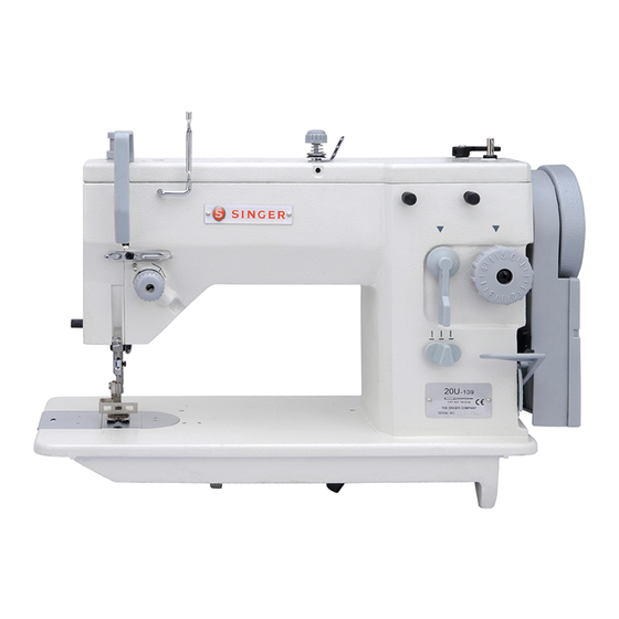
Product Description and Machine Specification Zigzag Sewing Machine 20U series Product Description Zigzag Sewing Machine Instruction Manual and Parts List... -
Page 7: Machine Specification
Machine Specification Table 1 – Machine Specification Singer model 20U-109 / 109C 20U-112 / 112C 20U-309 20E-910 Light to medium For sewing Stitch type Plain zigzag (Straight stitch) 3-step zigzag Editable, built-in pattern 100 Max. speed[1] 2,500 rpm 2,000 rpm... -
Page 8: Motor, Motor Pulley And V-Belt Specifications
1/3 HP (250W) 4-pole (low speed) clutch motor M type v-belt Motor, Table 2 – Machine Speed vs. Motor Pulley Diameter Motor Pulley and V-Belt Motor Pulley Diameter Machine Speed Specifications [mm] [spm] 20U-109 /109C 20U-112 / 112C 20U-309 20E-910 50 Hz 60 Hz 2,500... -
Page 9: Setup And Adjustment Instructions
Setup and Adjustment Instructions Table Cut-Out Drawing This hole for 20E only Figure 1 Zigzag Sewing Machine Instruction Manual and Parts List... -
Page 10: Oil Reservoir Installation
The oil reservoir should be fixed on the side of the machine table groove by using four nails (Figure 2). Oil Reservoir Installation Figure 2 Two rubber seats and two rubber using nails, and the other two corners for supporting the head rubber cushion on the hinge side portion should be fixed on the should be fixed on grooves by... -
Page 11: Belt Cover Installation
The machine belt cover The motor belt cover Install the machine belt cover so Install the motor belt cover so that that the hand wheel and v-belt motor pulley and v-belt will rotate Belt Cover move freely without interference, freely without interference. Installation and then tighten the screw at this position (see Figure 5). -
Page 12: The Connecting The Connectors To The Control Box (For 20E-910 Only)
Installations of the connecting connector refer on Figure 7. 1. Sensor cord connector The connecting 2. Feed step motor cord connector the connectors 3. Needle vibration step motor cord connector to the control 4. Power supply cord connector 5. Operation panel cord connector (for 20E-910 only) Note Each connector... -
Page 13: Lubrication
The rotating hook, and the area at Regularly apply one or two drops of the under of the needle plate. oil to the oil hole at the rotating hook (Oiling point at the Figure 8). Turn handwheel over toward you Lubrication until oil hole in the rotating hook appear in sight. -
Page 14: Needle And Thread
Selection of the proper needle needle and thread sizes to be used depends not only on the machine on the various machine models model, but also on the material and please refer to the table below. Needle and thread used. For selection of proper Thread Caution Table 4 - Needle and Thread... -
Page 15: Bobbin Case Attachment
Follow as shown in Figure 11. 1. Open bed slide. Bobbin Case 2. Raise latch ‘1’. Attachment 3. Lift out bobbin case ‘2’. Caution Switch off the machine. Do not operate the machine with throat plate left open. Figure 11 Zigzag Sewing Machine Instruction Manual and Parts List... -
Page 16: Bobbin Thread Winding
3.10 Stop motion of needle by loosening stop-motion screw ‘1’. Hold hand- wheel with left hand and turn stop- Bobbin motion screw toward you with right Thread hand. (See Figure 12). Winding Caution Do not guide or hold thread when winding the bobbin. -
Page 17: Bobbin Case Threading And Replacement
3.11 Hold bobbin case so that bobbin rotates in the direction of the arrow, and put bobbin in the bobbin case. Bobbin Case (Figure 14) Threading and Replacement Figure 14 Note When straight stitching, a Put thread into notch ’1’, and pull it better result under tension spring ‘2’... - Page 18 3.11 Hold bobbin case by latch ‘1’ and place it on spindle of bobbin case holder ‘2’ so that position finger ‘3’ Bobbin Case enters notch ‘4’ at right of bobbin Threading and case holder (see Figure 18). Replacement Release latch and press bobbin case firmly in place to assure proper Caution position.
-
Page 19: Machine Threading
3.12 When threading the machine head, Threading the machine in the order the needle bar should be at the shown in the Figure 19. highest point of its stroke. Leave thread approximately 4 cm Machine longer in the needle. Threading Caution Switch off the machine. -
Page 20: Stitch Length Adjustment (Except 20E-910)
3.13 Adjusting the stitch length: Adjusting the reverse stitch length: Turn stitch length dial ‘1’ in the Push feed reverse lever ‘2’ down for direction of the arrow, and align the reverse feed, and release it for Stitch Length desire number to marker dot ‘A’ on forward feed. -
Page 21: Needle Thread Tension Adjustment
3.15 Adjusting the tension of needle tion of the marker ‘+’), the tension thread using tension adjusting nut will increase. ‘1’ according to different sewing Turn the nut ‘1’ counterclockwise (in Needle condition. (Figure 22) direction of the market ‘-‘), the Thread Turn the nut ‘1’... -
Page 22: Bobbin Thread Tension Adjustment
3.17 Turn the tension adjusting screw ‘1’ clockwise (in direction of the marker ‘+’), the bobbin thread tension will Bobbin increase. Thread Turn the tension adjusting screw ‘1’ Tension counterclockwise (in direction of Adjustment the marker ‘-’), the bobbin thread tension will decrease. -
Page 23: Stitch Width Regulator (Except 20E-910)
3.19 The width of zigzag stitches is con- trolled with the spring biased stitch width regulating lever ‘1’ (Figure Stitch Width 26). Regulator Maximum zigzag width: (Except 20U-109 / 109C / 309: 9.0 mm 20E-910) 20U-112 / 112C: 12.0 mm Caution Do not make any needle position... -
Page 24: Needle Bar Frame Clamp Device
3.21 When straight stitching, a better When zigzag stitching, be sure the sewing result can be obtained by clamp is released. locking needle frame To release the clamp, turn the knob Needle Bar immovable with clamping ‘1’ counterclockwise as far as it will Frame Clamp device. -
Page 25: Straight And Zigzag Stitch Fitting (Except 20E-910)
3.22 Zigzag stitch Presser Foot ‘1’, Straight Stitch Presser Foot ‘1’, Needle Plate ‘2’ and Feed Dog ‘3’ Needle Plate ‘2’ and Feed Dog ‘3’ are used for straight and zigzag are used for straight stitching only. Straight and stitching. (Figure 29) (Figure 30) Zigzag Stitch Fitting (Except... -
Page 26: Spool Cap Usage
When using a reel type thread spool of spool pin ‘5’, and the tip of the 3.23 ‘2’, fit the spool cap ‘1’ onto the slotted spigot of the spool cap ’1’. thread spool hole ‘3’, which is sup- The spool cap ’1’ should never be Spool Cap plied by the machine accessory. -
Page 27: Thread Anti-Spill Net Usage
3.24 When using synthetic threads that from the bottom of cone ‘1’ leaving easily spill off the cone ‘1’, slip the the thread end to hang free at the thread anti-spill net ‘2’ furnished top of thread anti-spill net ‘2’. Thread Anti- with the machine over the thread (Figure 33) - Page 28 3.25 Knee operating presser foot lift Raise presser foot ‘12’ by presser (Figure 35) foot lifter ‘11’. Then loosen the lock nut holding screw ‘14’ and turn Bell cranks ‘1’ is fastened to the Knee Lifter screw ‘14’ as required when the underside of the bed, the bell crank Installation knee lifter knee plate ‘5’...
- Page 29 3.25 Knee operating stitch width control screw ‘8’ and move knee lifter shaft (Except 20U-309 20E-910) arm ‘3’ up or down as required, so (Figure 36) that height ‘10’ from its bent end ‘6’ Knee Lifter to bracket ‘9’ is 67 mm. Bell cranks ‘2’...
-
Page 30: Fittings For Buttonhole Stitching
3.26 Buttonhole Foot ‘1’, Needle plate ‘2’ used for buttonhole stitching. (Zigzag stitch) and Feed Dog ‘3’ are (Figure Fittings for Buttonhole 606652(20U-109/109C/309) Stitching 606402(20U-112/112C) 606688(20U-109/109C/309) 606502(20U-112/112C) 606692(20U-109/109C/112/112C/309) Figure 37 3.27 The hem foot ‘1’, needle plate ‘2’ 1. Needle position selector: (Straight stitch) and feed dog ‘3’... -
Page 31: Fittings For Zipper And Cord Sewing
3.28 The zipper presser foot ‘1’ is 2. Stitch width regulate: Straight designed to facilitate the placement stitch position of stitching closed to a raised edge 3. Needle plate: Straight stitch ‘3’ Fittings for as the following condition. (Figure Zigzag stitch ‘2’ Zipper and 4. -
Page 32: Maintenance
Maintenance Clean the machine periodically with a soft and dry cloth to remove the excess of dust on the machine Machine Head head. Do not use any kind of Cleaning lacquer thinner to wipe the surface. If the machine was idle for a long time, lubricate the machine accord- ing to the instructions of topics 3.6. -
Page 33: Troubleshooting
Troubleshooting Whenever sewing difficulty is encountered, check and make adjustments as follows. Problem Possible Causes Possible Solutions 1. Is machine properly threaded 1. Correct needle threading 2. Are thread guides or tension disc area lint-free 2. Remove lint & fluff in bobbin case & hook 3. -
Page 34: Parts List
Parts List... -
Page 35: Face Plate, Arm Top Cover And Arm Side Cover Components
Face Plate, Arm Top Cover and Arm Side Cover Components Part No. Description 109C 112C 554113-383 Thread take-up guard 606407 Take-up guard screw 606395 Face plate assembly 606632 Thread guide 606633 Thread guide screw 606634 Screw 554118-385 Back cover 606635 Screw 606433 Arm top cover assembly... -
Page 36: Side Cover
Face plate assembly GR232-8 Thread guide GS132-8 Screw GR480/2-8 Bobbin winder lever assembly J900112-001 Singer 'S' cameo J900112-002 Singer logo resin plate (front) J900112-003 Singer logo resin plate (back) J900020-xxx Model plate R03001 Rivet Zigzag Sewing Machine Instruction Manual and Parts List... -
Page 37: Thread Take-Up, Arm Shaft And Handwheel Components
Thread Take-up, Arm Shaft and Handwheel Components 31 32 Part No. Description 109C 112C 606640 Thread take-up assembly 606475 Thread take-up 606474 Thread take-up eyelet 606641 Thread take-up lever link 606471 Needle bar connecting link cap screw 606642 Needle bar connecting link assembly 606472 Needle bar connecting link 606466... - Page 38 Thread Take-up, Arm Shaft and Handwheel Components Part No. Description 109C 112C 606467 Needle bar connecting hinge pin 606465 Washer 606473 Thread take-up crank 606643 Hinge stud 606420 Hinge stud set screw 606469 Guide 606444 Screw 606644 Arm shaft and needle bar crank assembly 606484 Arm shaft 601478...
-
Page 39: Needle Bar, Presser Bar And Needle Plate Components
Needle Bar, Presser Bar and Needle Plate Components Zigzag Sewing Machine Instruction Manual and Parts List... -
Page 40: Needle Bar
Needle Bar, Presser Bar and Needle Plate Components Part No. Description 109C 112C 606646 Needle bar 606461 Needle bar 606463 Needle clamp screw 606647 Needle bar frame assembly 606456 Needle bar frame 606458 Indicator plate 606459 Indicator plate screw 606457 Eccentric pin set screw 606516 Set screw... -
Page 41: Zigzag Triangular Cam And Hook Advancing Crank Components
Zigzag Trian- gular Cam and Hook Advancing Crank Components Part No. Description 109C 112C 606420 Set screw 606539 Cam shaft assembly 606655 Cam shaft 606655-308 Cam shaft 606656 Cam shaft oil wick 410031 Zigzag cam and gear assembly 410056 Zigzag cam and gear assembly 606542 Cam shaft collar assembly 606541... - Page 42 Zigzag Trian- gular Cam and Hook Advancing Crank Components Part No. Description 109C 112C 606588 Oil felt 606657 Oil reservoir assembly 606586 Oil reservoir assembly 606658 Oil wick 606659 Oil reservoir bracket GW178-8 Spring GR243 Rubber cap GZ222-9 Following shaft GC149-8 Leaning gear GS202-8...
-
Page 43: Bight Amplitude, Bight And L-C-R Position Components
Bight Ampli- tude, Bight and L-C-R Position Components Zigzag Sewing Machine Instruction Manual and Parts List... - Page 44 Bight Ampli- tude, Bight and L-C-R Position Components Part No. Description 109C 112C 606511 Screw 606571 Washer 606569 Stop plate 606554 Lever arm regulating screw nut 606553 Lever arm regulating screw 606572 Screw 606577 Spring 606575 Regulating plate (left) 606576 Regulating Plate (right) 606574 Regulating plate holder...
-
Page 45: Arm Shaft (Upright) And Rotating Hook Drive Shaft Components
Arm Shaft (upright) and Rotating Hook Drive Shaft Components Part No. Description 109C 112C 541610 Bevel gear assembly (upper) 504101 Bevel gear set screw 606677 Arm shaft bushing (upper) 606678 Arm shaft (upright) 606527 Upright bushing (lower) 541609 Bevel gear assembly (lower) 504101 Bevel gear set screw 606585... -
Page 46: Arm Shaft
Arm Shaft (upright) and Rotating Hook Drive Shaft Components Part No. Description 109C 112C 606533 Upright bushing (upper) 606534 Bushing set screw 606679 Clutch sleeve assembly 504101 Clutch sleeve (upper) screw 504101 Clutch sleeve screw 606528 Connecting stud 606523 Retaining collar assembly 504101 Retaining collar screw 543914... -
Page 47: Hook And Bobbin Case Components
Hook and Bobbin Case Components Zigzag Sewing Machine Instruction Manual and Parts List... - Page 48 Hook and Bobbin Case Components Part No. Description 109C 112C 606517 Hook shaft collar assembly 606518 Hook shaft collar screw 606516 Set screw 606519 Hook shaft bushing (short) 541689 Bevel gear assembly 504101 Bevel gear screw 606516 Set screw 606515 Hook shaft bushing (long) 606520 Hook shaft...
-
Page 49: Feed Regulating Dial And Feed Reverse Lever Components
Feed Regulat- ing Dial and Feed Reverse Lever Components Zigzag Sewing Machine Instruction Manual and Parts List... - Page 50 Feed Regulat- ing Dial and Feed Reverse Lever Components Part No. Description 109C 112C 606618 Spring 606617 Stud lock pin 606609 Feed regulating stud 554138-383 Feed regulation dial 543803-004 Dial screw washer 544218-053 Dial screw 606610 Hinge stud 606685 Feed regulator & fork assembly 606611 Feed regulator assembly 606686...
-
Page 51: Feed Mechanism Components
Feed Mechanism Components Zigzag Sewing Machine Instruction Manual and Parts List... - Page 52 Feed Mechanism Components Part No. Description 109C 112C 606493 Connecting rod assembly 606434 Connecting rod cap screw 606492 Oil felt 606496 Hinge screw 606494 Hinge screw nut 606507 Feed lifting rock shaft assembly 606687 Roller and Stud 606508 Lifting rock shaft crank assembly 606500 Crank clamping screw 606497...
-
Page 53: Presser Bar Lifter And Thread Tension Components
6.10 Presser Bar Lifter and Thread Tension Components Zigzag Sewing Machine Instruction Manual and Parts List... -
Page 54: Presser Bar
6.10 Presser Bar Lifter and Thread Tension Components Part No. Description 109C 112C 606598 Hand lifter lever 606597 Hand lifter lever pin 606599 Screw 606413 Tension release lever 606412 Tension release lever screw spring 606411 Tension release lever screw 410413 Thread retainer 606518 Thread retainer screw... -
Page 55: Feed Mechanism Components For 20E-910 Only
6.11 Feed Mechanism Components for 20E-910 only Zigzag Sewing Machine Instruction Manual and Parts List... - Page 56 6.11 Feed Mechanism Components for 20E-910 only Part No. Description 109C 112C Feed pulse motor 53C/7-11 Screw 50020004 Motor base for feeding pulse motor 53C/7-5 Screw 50020029 53C/7-2 Feed regulator connecting bar pin 500B0015 Screw 53C/7-7 Feed pulse motor crank pin 53C/7-6 Feed pulse motor crank Feeding sensor shade...
-
Page 57: Needle Bar Vibration Components For 20E-910 Only
6.12 Needle Bar Vibration Components for 20E-910 only Part No. Description 109C 112C Screw Needle bar vibrating motor cover 53C/5-12 Screw GB/T70.1-2000 Needle bar vibrating pulse motor 53C/5-8 Needle bar vibrating motor frame 53C/5-7 Screw 50020029 Needle bar vibrating base 53C/5-2 50031003 Screw... -
Page 58: Control System Components For 20E-910 Only
6.13 Control System Components for 20E-910 only Part No. Description 109C 112C 53C/8-2 Control box 53C/8-5 Operation panel 53C/8-4 Operation panel cable 53C/5-18 Operation panel bracket GB/T845 Screw Screw Zigzag Sewing Machine Instruction Manual and Parts List... -
Page 59: Thread Stand Components
6.14 Thread Stand Components Zigzag Sewing Machine Instruction Manual and Parts List... -
Page 60: Thread Stand
6.14 Thread Stand Components Part No. Description 109C 112C 30102032 Thread bar (lower) 30128024 Washer 10128006 Rubber washer N02001 30101029 Bracket (2 spools) 30103044 Spool holder 30102033 Spool pin 30123014 Cushion 30111007 Spool tray W02002 Spring washer N01005 L02004 Screw N01004 S04002 Screw... -
Page 61: Accessories And Attachments
6.15 Accessories Attachments Zigzag Sewing Machine Instruction Manual and Parts List... - Page 62 6.15 Accessories Attachments Part No. Description 109C 112C 606690 Accessory box 1910-05 Needle (1910-05 #14) 606691 Zipper foot 606692 Presser foot assembly (for button holing) 606693 Presser foot assembly (for straight stitching) 606694 Hemmer foot assembly 606695 Needle plate (for straight stitching) 606696 Needle plate (for embroidery) 606697...
-
Page 63: Belt Cover Components And Extra Parts
6.16 Belt Cover Components and Extra Parts Part No. Description 109C 112C 281840-383 Belt cover assembly 281833-383 Belt cover (upper) 281834-383 Belt cover (upper) cover 549116 Belt cover (upper) screw 504063-451 Belt cover (upper) screw 543875-104 Belt cover (upper) screw washer 544241 Belt cover (upper) screw stud 281835-383... - Page 64 SINGER and the Cameo "S" Design are exclusive trademarks of The Singer Company Limited S.à r.l. or its Affiliates. ©2011 The Singer Company Limited S.à r.l. or its Affiliates. All rights reserved. www.singer.com...