Table of Contents
Advertisement
Advertisement
Table of Contents

Related Manuals for New Home NH60

Summary of Contents for New Home NH60
- Page 1 SERVICE MANUAL & PARTS LIST MODEL: NH60...
-
Page 2: Table Of Contents
INDEX LOCATE AND IDENTIFY PARTS ....................3 WIND THE BOBBIN ........................4 PREPARE YOUR TOP THREAD ....................5 LCD DISPLAY ..........................6 WHAT TO DO WHEN ........................ 7-9 CHANGING EXTERNAL PARTS FACE COVER..........................10 FREE-ARM COVER ........................11 FRONT COVER ........................12-13 REAR COVER ..........................14 MECHANICAL ADJUSTMENT PRESSER BAR HEIGHT ......................15 NEEDLE DROP POSITION ......................16 ADJUSTMENT OF HOOK TIMING .....................17... -
Page 3: Locate And Identify Parts
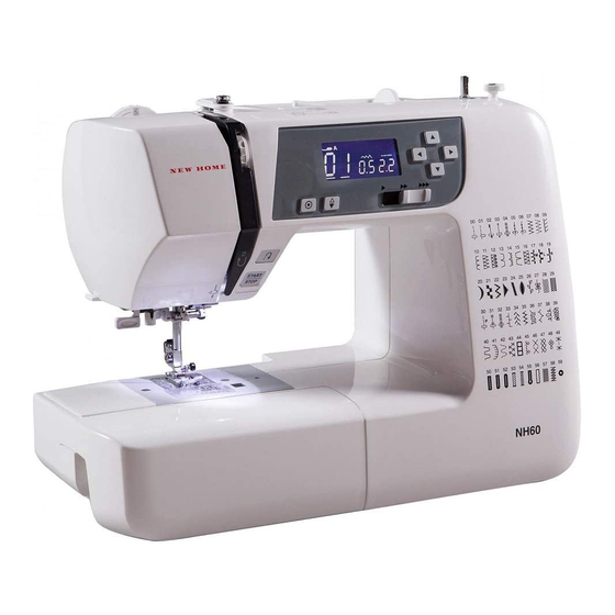
LOCATE AND IDENTIFY PARTS BOBBIN WINDER SPOOL PIN SPINDLE THREAD BOBBIN WINDER TENSION DIAL STOPPER FACE COVER VALUE SET BUTTONS THREAD CURSOR BUTTONS CUTTER LCD DISPLAY SPEED CONTROL SLIDER NEEDLE NEEDLE POSITION UP/ THREADER DOWN BUTTON AUTO-LOCK BUTTON REVERSE STITCH BUTTON NEEDLE PLATE START/STOP BUTTON EXTENSION TABLE... -
Page 4: Wind The Bobbin
WIND THE BOBBIN Hold the thread with both hands and pass the bobbin winding tension disc (1). Pass the thread through the hole in the bobbin from the inside to the outside. Put the bobbin on the bobbin winder spindle (2). Push the bobbin winder spindle to the right. -
Page 5: Prepare Your Top Thread
PREPARE YOUR TOP THREAD Raise the thread take-up lever to its highest position by turning the handwheel counterclockwise. Raise the presser foot lifter. Place a spool on the spool pin, with the thread coming off the back of spool. While holding the thread near the spool, Draw the end of the thread around the draw the end of the thread down around upper thread guide. -
Page 6: Lcd Display
LCD DISPLAY The LCD display shows the following information when the machine is turned on. STITCH PATTERN NUMBER CURSORS STITCH WIDTH STITCH LENGTH Press the cursor key to move the cursor under the stitch pattern number. The cursors appear under both digits when turning the power on. Press the value set keys to change the stitch pattern number until the pattern number of the desired stitch is indicated. -
Page 7: What To Do When
WHAT TO DO WHEN CONDITION CAUSE HOW TO FIX REFERENCE 1. SKIPPING Needle is not inserted Insert the needle properly. STITCHES properly. Needle is bent or worn. Change the needle. Incorrectly threaded. Rethread. Needle or thread are Use the recommended sewing inappropriate for the needle and thread. - Page 8 CONDITION CAUSE HOW TO FIX REFERENCE 3. BREAKING Initial sewing speed is Start with medium speed. UPPER too fast. THREAD. Thread path is incorrect. Use the proper thread path. Needle is bent or dull. Replace with a new needle. 4. BREAKING BOBBIN Top tension is too strong.
- Page 9 CONDITION CAUSE HOW TO FIX REFERENCE 6. NOISY Backlash between hook Eliminate the backlash. OPERATION gear and lower shaft gear is too great. Lower shaft gear is loose. Eliminate the looseness. Inappropriate belt See part removal and tension. replacement “Driving motor (DC motor)”.
-
Page 10: Changing External Parts
CHANGING EXTERNAL PARTS FACE COVER TO REMOVE: 1. Loosen the setscrew (1) and lift the face cover to disengage the rib on the inside. Remove the face cover (2). TO ATTACH: 2. Follow the above procedures in reverse. -
Page 11: Free-Arm Cover
CHANGING EXTERNAL PARTS FREE-ARM COVER TO REMOVE: 1. Loosen the setscrew (1) and (2). Move the free-arm cover (3) to the left. remove the free-arm cover. TO ATTACH: 2. Follow the above procedures in reverse. -
Page 12: Front Cover
CHANGING EXTERNAL PARTS FRONT COVER (1) TO REMOVE: 1. Remove the face cover and free-arm cover (see page 8 and 9). 2. Remove the setscrews (1) (2 pcs.). 3. Remove the setscrews (2) (5 pcs.), back cover (3) . 4. Remove the setscrews (4) (2 pcs.). 5. -
Page 13: Front Cover
CHANGING EXTERNAL PARTS FRONT COVER (2) 1. Disengage the front cover and rear cover hooks. 2. Remove the front cover. TO ATTACH: 3. Follow the above procedures in reverse. -
Page 14: Rear Cover
CHANGING EXTERNAL PARTS REAR COVER TO REMOVE: 1. Remove the face cover and free-arm cover (see page 8 and 9). 2. Remove the setscrews (A) (4 pcs.). 3. Remove the setscrews (B) (5 pcs.) and back cover. 4. Remove the setscrews (C) (2 pcs.). Remove the rear cover. TO ATTACH: 5. -
Page 15: Mechanical Adjustment
MECHANICAL ADJUSTMENT PRESSER BAR HEIGHT The distance between the bottom of the presser foot in up position and the needle plate should be 6.0 1. Remove the face plate and needle. 2. Lower the feed dog below the needle plate. Place a block 6 mm thick under the presser foot and lower the presser foot lifter (1). -
Page 16: Needle Drop Position
MECHANICAL ADJUSTMENT NEEDLE DROP POSITION Set the stitch pattern to “ ”. The standard needle drop position should be at center of the needle plate hole (1). Select zigzag stitch “ ”, and set the stitch width at “5.0”. The clearance between the needle and the edge of the needle hole in the needle plate should be at least 0.2 mm on either side. -
Page 17: Adjustment Of Hook Timing
MECHANICAL ADJUSTMENT ADJUSTMENT OF HOOk TIMING MACHINE SETTING: 1. Remove the free-arm cover. 2. Select Pattern: No.00 (straight stitch) 3. Turn the power switch off. TO ADJUST: 1. Remove the needle, presser foot, needle plate (A) and bobbin holder (B). 2. -
Page 18: Replacing Hook
MECHANICAL ADJUSTMENT REPLACING HOOk If the hook point is damaged or too worn, the hook needs to be replaced. TO REMOVE: 1. Remove the needle plate and bobbin holder. 2. Remove the front cover (see page 12 and 13). 3. Turn the handwheel toward you to align the hook point and the right edge of feed dog teeth. 4. -
Page 19: Adjustment Of Needle Bar Height
MECHANICAL ADJUSTMENT ADJUSTMENT OF NEEDLE BAR HEIGHT NEEDLE BAR HEIGHT MACHINE SETTING: 1. Remove the face cover. (See page 10) 2. Select Pattern: No.00 (straight stitch). 3. Turn the power switch off. TO ADJUST: 1. Remove the needle, presser foot, needle plate (A) and bobbin holder (B). 2. -
Page 20: Clearance Between Needle And Tip Of Hook Rotary
MECHANICAL ADJUSTMENT CLEARANCE BETWEEN NEEDLE AND TIP OF THE ROTARY HOOk * The clearance between the needle and the point of hook should be –0.1 to +0.05 mm. ADJUSTMENT PROCEDURE: 1. Remove the needle plate and bobbin holder. Attach the master needle. Turn the power switch on and set the zigzag width at maximum. -
Page 21: Feed Dog Height
MECHANICAL ADJUSTMENT FEED DOG HEIGHT The highest position of the feed dog should be between 0.80 and 0.90 mm from the surface of the needle plate. TO CHECk: 1. Remove the presser foot. 2. Turn the power switch on. 3. Turn the handwheel toward you to set the feed dog at the highest position. Remove the free-arm cover. -
Page 22: Top Tension
MECHANICAL ADJUSTMENT TOP TENSION The top tension should be between 65 and 80g when pulling the thread up in the direction of C. * Use polyester sewing thread #50 (White). * If it is not within the above limit, adjust as follows. 1. -
Page 23: Replacing The Electronic Components
REPLACING THE ELECTRONIC COMPONENTS CIRCUIT BOARD-A CONNECTION NOTE: Do not disconnect the connectors by pulling on cord. To disconnect, grasp the connector, not the cord. Printed circuit board P (Black) Feed motor (White) Bobbin winding switch (Blue) Power switch (White) Zigzag width motor (Green) Printed circuit board F (White) Printed circuit board L (White) -
Page 24: Self-Diagnostic Test
SELF-DIAGNOSTIC TEST PREPARATION: 1. Turn the power switch off. 2. Move the bobbin winder spindle to the left. 3. Raise the feed dog. 4. Set the speed control lever to the left. 5. Remove the presser foot and raise the presser foot lifter. 6. - Page 25 SELF-DIAGNOSTIC TEST STEP AND PROCEDURE ITEMS CORRECT CONDITION DEFECTIVE CONDITION TO CHECK Sewing lamp and LCD backlight lit. LCD Sewing lamp does not lit. Turn on the power switch while FUNCTION OF displays “01”. LCD backlight does not lit. simultaneously pressing the start/stop LCD, BUZZER LCD does not display “01”.
- Page 26 SELF-DIAGNOSTIC TEST STEP AND PROCEDURE CORRECT CONDITION DEFECTIVE CONDITION ITEMS TO CHECK (Not applicable for this model) Turn the handwheel toward you. Buzzer does not sound. LCD displays “SC 06”. Lower the needle bar from its highest to Stitch width or length symbol Upper shaft its lowest position.
- Page 27 SELF-DIAGNOSTIC TEST STEP AND DEFECTIVE CONDITION PROCEDURE CORRECT CONDITION ITEMS THE FOOT CONTROL TO CHECK Attach the foot control to the sewing LCD displays “SC 08”. The foot control. FOOT machine. Symbol does not appear. CONTROL Depress the foot control as far as it Buzzer does not sound.
- Page 28 SELF-DIAGNOSTIC TEST Buzzer sounds after few seconds when the self-diagnostic test has been finished. The test result has been determined. CORRECT: Buzzer sounds and LCD displays “00” DEFECTIVE: Caution buzzer sounds and LCD displays the defective part number. Refer to page 23-25 and fix the defective part.
-
Page 29: Circuit Board-A
REPLACING THE ELECTRONIC COMPONENTS CIRCUIT BOARD-A (1) TO REMOVE: 1. Remove the front cover. (see pages 12 – 13) 2. Pull out connectors from the circuit board-A. 3. Remove the screws (6 pcs.) and the circuit board-A. TO ATTACH: 4. Follow the above procedures in reverse. NOTE: Do not disconnect the connectors by pulling on cord. -
Page 30: Circuit Board-A
REPLACING THE ELECTRONIC COMPONENTS CIRCUIT BOARD-A(2) SETTING THE CIRCUIT BOARD A After install the circuit board A, select the appropriate setting of the circuit board A. 1. Turn the power switch on while simultaneously pressing left cursor button “ ” and the right cursor “... -
Page 31: Driving Motor
REPLACING THE ELECTRONIC COMPONENTS DRIVING MOTOR TO REMOVE: 1. Remove the front cover. 2. Remove the setscrews (2pcs.) and the driving motor and the belt. TO ATTACH: 1. Install the driving motor and the motor belt. Tighten them with setscrews (2 pcs.) lightly. 2. -
Page 32: Switching Regulator Unit
REPLACING THE ELECTRONIC COMPONENTS SWITCHING REGULATOR UNIT TO REMOVE: 1. Remove the front cover and the rear cover. 2. Remove the setscrews A (3 pcs.) and the switching regulator. 3. Remove the setscrews B (4 pcs.). TO ATTACH: 4. Follow the above procedures in reverse. Switching regulator Setscrew A... -
Page 33: Adjusting Buttonhole Lever Position
MECHANICAL ADJUSTMENT ADJUSTING BUTTONHOLE LEVER POSITION TO ADJUST THE BUTTONHOLE LEVER GUIDE: 1. Enter the buttonhole sensor adjusting mode. (See below. The LCD should display BH symbol.) 2. Remove the face cover (see page 8) and loosen the setscrew (A). 3. -
Page 34: Parts List
MODEL: NH60 PARTS LIST... - Page 35 MODEL: NH60 PARTS LIST PARTS DESCRIPTION 808601005 Upper shaft (unit) 000111201 Hexagonal socket screw 4x4 000112800 Hexagonal socket screw 4x6 000036201 Washer FT80 508120006 Shaft fixing metal 823110010 Felt 508054101 Shaft fixing metal 820166001 Lower shaft ring 808003001 Upper shaft shielding plate...
- Page 36 MODEL: NH60 PARTS LIST...
- Page 37 MODEL: NH60 PARTS LIST PARTS DESCRIPTION 808640006 Presser bar base plate (unit) 808006200 Presser bar base plate 808007005 Thread tension release lever 503041007 Thread tension release spring 502024001 Presser foot lifter 000001609 Snap ring E-5 808076005 Presser bar spring adjusting plate...
- Page 38 MODEL: NH60 PARTS LIST...
- Page 39 MODEL: NH60 PARTS LIST PARTS DESCRIPTION 808632005 Hook race (whole unit) 808629009 Hook race (unit) 808634018 Lower shaft (unit) 808027001 Lower shaft 508021006 Upper shaft gear 000004200 Spring pin 3x18 000038502 Washer 508054008 Shaft fixing metal 820166001 Lower shaft ring...
- Page 40 MODEL: NH60 PARTS LIST...
- Page 41 MODEL: NH60 PARTS LIST PARTS DESCRIPTION 808626006 Needle plate (unit) 808067003 Needle plate 808068004 Support needle plate 000163703 Setscrew 2x3.5 502015009 Spring 000015503 Snap ring SC-2.4 502016000 Hook cover plate release button 502202005 Supporter plate 000130206 Setscrew 1.7x2.5 (B) 508116009...
- Page 42 MODEL: NH60 PARTS LIST...
- Page 43 MODEL: NH60 PARTS LIST PARTS DESCRIPTION 808619604 Rear cover (unit) 808050508 Rear cover 827503108 Top cover thread guide (unit) 000162001 Setscrew 2.6x5 650503403 Thread guide (unit) 000014409 Snap ring CS-8 502007008 Spool pin 502008009 Spool pin support plate 000120203 Setscrew 3x8 (B)
- Page 44 MODEL: NH60 PARTS LIST...
- Page 45 MODEL: NH60 PARTS LIST PARTS DESCRIPTION 808630081 Front cover (unit) 808051495 Front cover 808072056 Panel 808114006 Double-stick sheet 808103002 Front cover lid 808071103 Button 1 808054100 Button 2 808055008 Slide volume 808056102 Slide volume set plate 000160700 Setscrew 2.6x6 (B)
- Page 46 MODEL: NH60 PARTS LIST...
- Page 47 MODEL: NH60 PARTS LIST PARTS DESCRIPTION 808870007 Attachment (unit) 822804118 Satin foot (unit) 829801002 Zipper foot (unit) 825817009 Blind hem foot (unit) 822801001 Overedge foot (unit) 102261000 Bobbin 639804000 Needle set (unit) 653802002 Screw key 802424004 Lint brush 647808009 Seam ripper (Buttonhole opener)