Table of Contents
Advertisement
Quick Links
INSTALLATION GUIDE
•
OWNER'S GUIDE
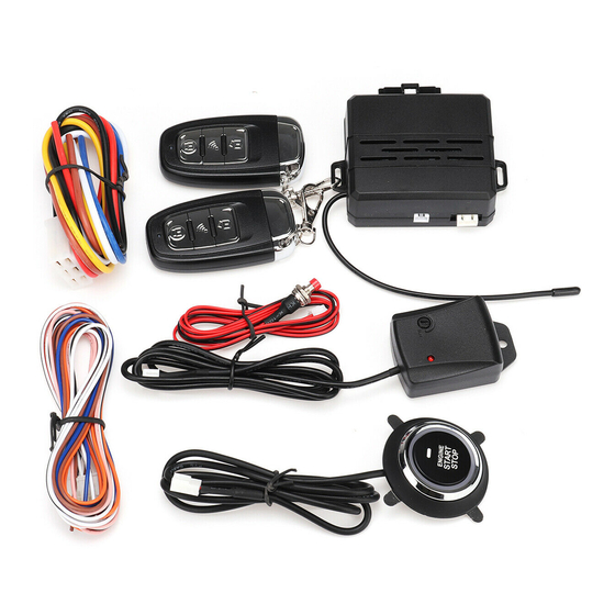
REMOTE STARTER
MODELS RS102/RS102E, RS112/RS112E, RS122/RS122E
CONTENTS
System Features ......................................1
System Components ....................................1
Required Tools .......................................1
Technical Assistance .................................1
Before You Begin .....................................2
Precautions ..........................................2
Testing Your Wires ...................................2
Locating & Making Connections ......................4-5
Neutral Safety Switch ................................5
Connecting 18-Pin Harness ............................6
Connecting 4-Relay Harness ...........................6
Antenna Placement ....................................6
Anti-Theft System ....................................7
Optional Connections ...............................7-9
Operating Instructions ...............................9
Programming Instructions ..........................9-10
Technical Assistance
All tech personnel are expertly qualified to answer any technical questions.
Technicians are available Monday through Friday from 9:00 a.m. until 8:00 p.m. and Saturday 10:00 a.m. until 4:00 p.m.
Address
288 Canton Avenue • Wintersville, Ohio 43953
Telephone
Phone: 740-264-4710 • 800-878-8007 • Fax: 740-264-7306
Advertisement
Table of Contents

Related Manuals for Bulldog Security RS102


Summary of Contents for Bulldog Security RS102
-
Page 1: Table Of Contents
INSTALLATION GUIDE • OWNER’S GUIDE REMOTE STARTER MODELS RS102/RS102E, RS112/RS112E, RS122/RS122E CONTENTS System Features ........1 System Components ........1 Required Tools ........1 Technical Assistance .........1 Before You Begin ........2 Precautions ..........2 Testing Your Wires ........2 Making Connections .........2-4 Locating & Making Connections ......4-5 Neutral Safety Switch ........5... -
Page 2: System Features
SYSTEM FEATURES Four-Button Extended Range Remotely start your car to run the heater or air conditioning from an extended distance. Remote Control Keyless Entry Remotely locks and unlocks your power door locks. Trunk Release Remotely opens your trunk with a push of a button. (Optional part #775 required) Remote Programmable Run Time Remotely program your vehicle to run 5 to 15 minutes. -
Page 3: Before You Begin
It is computer controlled and manufactured in the U.S.A. The dependability and variety of features make Bulldog Security the leader in the industry. Enjoy your new remote starter for years to come! This remote system is designed to start your vehicle by sending a command signal from the remote transmitter or by programming automatic temperature or timed start. -
Page 4: Making Wiring Connections
MAKING WIRING CONNECTIONS 1. Strip back two inches of insulation on the wire from the keyless entry. Two Inches of Bare Wire 2. Strip back one inch of insulation on the wire you need to connect to. One Inch of Bare Wire 3. -
Page 5: Locating & Making Connections
2. Twist upper wires together, twist lower wires together as shown. 3. Lay upper twisted pair of wires over right wire as shown. Bring lower twisted pair of wires up to meet the left wire as shown. 4. Use electrical tape to wrap, be sure to cover about 2 inches on either side of connection. Secure with wire ties as shown. - Page 6 3. If your vehicle has (2) ignition wires, connect the second WHITE wire from the 4-relay harness to 4. If your vehicle has (3) ignition wires (some GMs) connect the second WHITE wire from the 4-relay harness to both the second and third ignition wires in the vehicle. ACCESSORY WIRE(S) THAT POWER THE HEATER/BLOWER MOTOR (+12V in run or on positions) This wire is also in the main ignition switch harness usually located in the steering column.
-
Page 7: Neutral Safety Switch
NEUTRAL SAFETY SWITCH PRE-1996 GM REAR WHEEL DRIVES WITH PURPLE CRANK WIRE Optional part #775 required. MECHANICAL NEUTRAL SAFETY SWITCH (Rear Wheel Drive Only) When installing a Bulldog remote starter on GM vehicles or Dodge Dakotas built prior to 1996, you must: Use the diagram below to create a circuit that will prevent the remote starter from starting the vehicle unless the key is removed from the ignition switch. -
Page 8: Antenna Placement
ANTENNA PLACEMENT ANTENNA For best results, run the antenna (YELLOW WIRE WITH BLACK TIP from the back of the unit) as Antenna Wire straight as possible. Do not place the antenna next to any metal parts or the vehicle’s main Antenna Tube computer control module. - Page 9 Testing Switch Wire and Motor Wires Before connecting, you must now determine which wire is the switch wire and which is the motor wire. Cut both the lock and unlock wires in half. Start with both of the lock wires by placing the clip end of your test light to ground, hold the door lock switch in the lock position, make sure you are using the master switch (usually on the driver’s door) and probe both lock wires looking for voltage.
-
Page 10: Programming Instructions
TRUNK RELEASE OUTPUT (Optional Part #775 NEGATIVE TRUNK RELEASE POSITIVE TRUNK RELEASE required) Optional part #775 required. Locate the trunk release wire coming from TO FACTORY TRUNK WIRE TO FACTORY TRUNK WIRE the back of the trunk release switch. To YELLOW YELLOW determine if your trunk release is tripped... -
Page 11: How To Use Your Remote Transmitter
Programming Runtime with Brake not Pressed Press and hold Button #4. The parking lights will flash once for every five (5) minutes you want to program. Release button at desired runtime. Maximum length, 15 minutes. Clearing the E-Prom Press and hold the brake, now cycle the key in the ignition switch from OFF to RUN (not start) five (5) times within four (4) seconds.