Epson TM-T88IV Technical Reference Manual
For restick
Hide thumbs
Also See for TM-T88IV:
- Technical reference manual (104 pages) ,
- User manual (60 pages) ,
- Step by step manual for installing (14 pages)
Table of Contents
Advertisement
Technical Reference Guide
Product Overview
Describes features and general specifications for the product.
Setup
Describes setup and installation of the product and peripherals.
Application Development Information
Describes how to control the printer and necessary information
when you develop applications.
Handling
Describes how to handle the product.
Appendix
Describes interfaces, connectors and character code tables.
M00017501
Rev. B
Advertisement
Table of Contents

Related Manuals for Epson TM-T88IV


Summary of Contents for Epson TM-T88IV
- Page 1 Technical Reference Guide Product Overview Describes features and general specifications for the product. Setup Describes setup and installation of the product and peripherals. Application Development Information Describes how to control the printer and necessary information when you develop applications. Handling Describes how to handle the product.
- Page 2 • Neither is any liability assumed for damages resulting from the use of the information contained herein. • Neither Seiko Epson Corporation nor its affiliates shall be liable to the purchaser of this product or third parties for damages, losses, costs, or expenses incurred by the purchaser or third parties as a result of: accident, misuse, or abuse of this product or unauthorized modifications, repairs, or alterations to this product, or (excluding the U.S.) failure to strictly comply with Seiko Epson Corporation’s operating...
-
Page 3: Revision History
Revision History Revision page Details of change Rev. A All pages Newly authorized Rev. B page 42 Description of European models is added to the table of the factory setting for Memory switch 5. Description of the download URLs is changed. page 66 Description of cleaning when using linerless lable paper is page 74... -
Page 4: For Safety
For Safety Key to Symbols The symbols in this manual are identified by their level of importance, as defined below. Read the following carefully before handling the product. You must follow warnings carefully to avoid serious bodily injury. WARNING Provides information that must be observed to prevent damage to the equipment or loss of data. -
Page 5: Warnings
• Shut down your equipment immediately if it produces smoke, a strange odor, or unusual noise. Continued use may lead to fire. Immediately unplug the equipment and contact your dealer or a Seiko Epson service center for advice. • Never attempt to repair this product yourself. Improper repair work can be dangerous. -
Page 6: Cautions
Cautions • Do not connect cables in ways other than those mentioned in this manual. Different connections may cause equipment damage or fire. • Be sure to set this equipment on a firm, stable, horizontal surface. CAUTION The product may break or cause injury if it falls. •... -
Page 7: About This Manual
About this Manual Aim of the Manual This manual was created to provide information on development, design, and installation of POS systems and development and design of printer applications for developers. Manual Content The manual is made up of the following sections: Chapter 1 Product Overview Chapter 2... -
Page 8: Table Of Contents
Contents ■ Revision History........................3 ■ For Safety ..........................4 Key to Symbols............................4 Warnings ..............................5 Cautions ..............................6 ■ Restriction of Use ........................6 ■ About this Manual ........................ 7 Aim of the Manual ..........................7 Manual Content .............................7 ■ Contents..........................8 Product Overview ................11 ■... - Page 9 Power Supply Unit (PS-180)........................31 Setup .....................33 ■ Flow of Setup ........................33 ■ Installing the Printer ......................34 Important Notes on Horizontal Installation ..................34 Important Notes on Wall Hanging ..................... 34 ■ Setting the DIP Switches .....................35 Setting Procedure ..........................35 For Serial Interface ..........................
- Page 10 Handling ..................69 ■ Installing and Replacing Roll Paper ................. 69 ■ Attaching/Removing the Connector Cover ..............71 Attaching the Connector Cover ......................71 Removing the Connector Cover......................71 ■ Removing Jammed Paper ....................72 When the Roll Paper Cover Cannot be Opened................72 ■...
-
Page 11: Product Overview
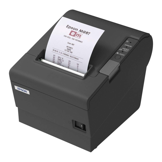
This chapter describes features and specifications of the product. Features The TM-T88IV for ReStick is a thermal printer that prints on the recommended liner-free label and the thermal paper, which has the same usability as the de facto standard receipt printer, TM- T88IV. -
Page 12: Product Configuration
Product Configuration Buzzer The buzzer function is available Color • ECW (Epson Cool White) • EDG (Epson Dark Gray) Accessories Attachments • Roll paper (for operation check) • User’s manual • Power switch cover • Connector cover • Locking wire saddle (only for USB interface model) •... -
Page 13: Parts Name And Function
Before turning the printer off, it is recommended to send a power-off command to the printer. If you use the power-off sequence, the latest maintenance counter values are saved. (Maintenance counter values are usually saved every two minutes.) For detailed information about ESC/POS commands, see the TM-T88IV Specification (ReStick Model). -
Page 14: Power Switch Cover
Power Switch Cover Install the power switch cover that comes with the TM-T88IV onto the printer to prevent inadvertent changing of the power switch, to prevent tampering, and to improve the appearance of the printer. To reset the printer when the power switch cover is installed, insert a long, thin object (such as the end of a paper clip) into the hole in the power switch cover and press the power switch. -
Page 15: Connectors
Chapter 1 Product Overview PAPER OUT LED • Lights when there is no more roll paper. When you select to use the thermal roll paper by DIP switches, this LED lights also when there is little paper remaining. • Off when there is a sufficient amount of roll paper remaining. •... -
Page 16: Error Status
Error Status There are three possible error types: automatically recoverable errors, recoverable errors, and unrecoverable errors. Automatically Recoverable Errors Printing is no longer possible when automatically recoverable errors occur. They can be recovered easily, as described below. Error LED flash code Error Error description Recovery measure... -
Page 17: Unrecoverable Errors
Chapter 1 Product Overview Unrecoverable Errors Printing is no longer possible when unrecoverable errors occur. The printer must be repaired. Turn off the power immediately when unrecoverable errors occur. CAUTION Error LED flash code Error Error description Approx. 160 ms Memory R/W error After R/W checking, the printer does not work correctly. -
Page 18: Nv Memory (Non-Volatile Memory)
NV Memory (Non-Volatile Memory) The printer has NV memory which includes the user NV memory and NV graphics memory that users can use. NV memory can be rewritten about 100,000 times. As a guide, NV memory rewriting should be 10 times or less a day when you program applications. CAUTION NV Graphics Memory Graphics such as shop logos to be printed on receipts can be stored. - Page 19 Chapter 1 Product Overview Procedure Open the roll paper cover. While pressing the FEED button, turn the power on. Press the FEED button once. Close the roll paper cover. After instructions are printed, open the roll paper cover. Press the FEED button once. Close the roll paper cover.
-
Page 20: Product Specifications
Product Specifications Printing method Thermal line printing Cutting method Partial cut (cutting with one point in left edge left uncut) Roll paper (single-ply) Width: 79.5 ± 0.5 mm (3.13 ± 0.02") Interface Serial (RS232C), Parallel (IEEE1284), LAN (10/100BASE-T), USB (Full-speed), Wireless LAN (IEEE802.11b) Buffer Receive buffer 4 KB/45 bytes (selectable using the DIP switch 1-2) -
Page 21: Printing Specifications
Chapter 1 Product Overview Humidity Operating: Recommended liner-free label: 10 to 80% RH Thermal roll paper: 10 to 90% RH Storage: 10 to 90% RH, except for paper Overall dimensions 148 × 145 × 195 mm {5.83 × 5.71 × 7.68"} (H × W × D) Weight (mass) Approx. -
Page 22: Character Specifications
Character Specifications Number of characters • Alphanumeric characters: 95 • Extended graphics: 128 × 11 pages (including user-defined page) • International characters: 48 Character structure 58mm paper width model 80mm paper width model Memory switch Font Character Character setting structure structure MSW 5-2 ON Font A... -
Page 23: Character Size
Chapter 1 Product Overview Character Size Double-width/ Standard Double-height Double-width Double-height Character structure W × H W × H W × H W × H *2*3 *2*3 *2*3 *2*3 (mm) (mm) (mm) (mm) — — — — 13 × 24 1.25 ×... -
Page 24: Printable Area
Printable Area 58mm paper width model The printable area of a paper with width of 57.5 ± 0.5 mm {2.26 ± 0.02"} is 52.5 mm{2.07"} (420 dots), and the space on the right side is approximately 2.15 mm {0.08”} and that on the left side is approximately 2.85 mm {0.11"}. - Page 25 Chapter 1 Product Overview 80mm paper width model The printable area of a paper with width of 79.5 ± 0.5 mm {3.13 ± 0.02"} is 72 mm {2.83 "} (576 dots) and the space on the right and left sides are approximately 3.75 mm {0.15"}. Paper width All the numeric values are typical.
-
Page 26: Printing And Cutting Positions
Printing and Cutting Positions Last line of a previous receipt Manual-cutter position Approx. 29 Approx. 15 Autocutter blade position Center of the print dotline Printable area Paper feed direction [units: mm (All the numeric values are typical.)] The values above may vary slightly as a result of paper slack or variations in the paper. Take the notice into account when setting the cutting position of the autocutter. -
Page 27: Paper Specifications
Chapter 1 Product Overview Paper Specifications Paper type Specified thermal paper Recommended liner-free label Form Roll paper Size Roll paper diameter 83 mm {3.27"} maximum Roll paper spool Inside: 12 mm {0.47"}, Outside: 18 mm {0.71"} Take-up roll paper width 58 mm paper width model: 58 + 0.5/-1.0 mm 80 mm paper width model: 80 + 0.5/-1.0 mm Paper width... -
Page 28: Electrical Characteristics
Electrical Characteristics Supply voltage DC24V ± 7% Current consumption Standby Mean: Approximately 0.1A (at 24V, 25°C, normal Maximum 1A for drawer kick-out driving. print density) Operating Mean: Approximately 1.6A Note) When print ratio is approximately 18% • Font A • 48 columns •... -
Page 29: Environmental Conditions
Ambient temperature Acoustic noise (Operating) Approximately 56 dB (Bystander position) Note) The values above are measured in the Epson evaluation condition. The acoustic noise differs depending on the paper used, printing contents, or the setting values such as print speed or... -
Page 30: External Dimensions And Mass
External Dimensions and Mass • Height: Approximately 148 mm {5.83"} • Width: Approximately 145 mm {5.71"} • Depth: Approximately 195 mm {7.68"} • Mass: Approximately 1.8 kg {3.96 lb} (except for roll paper) [Units: mm]... -
Page 31: Power Supply Unit Specifications
Chapter 1 Product Overview Power Supply Unit Specifications Power Supply Unit (PS-180) [Unit: mm] Electric Input conditions input voltage (rating): 90 to 264VAC characteristics (100VAC -10% to 230VAC +15%) Frequency (rating): 50/60 Hz ± 3 Hz Power consumption (rating): 100VA Output conditions Output voltage (rating): 24VDC ±... -
Page 33: Setup
Chapter 2 Setup Setup This chapter describes setup and installation of the product and peripherals. Flow of Setup This chapter consists of the following sections along with the setup flow of the product and peripherals. Installing the Printer (page 34) Setting the DIP Switches (page 35) Setting the Memory Switches (page 42) Adjusting the Near-End Sensor for Thermal Roll Paper (page 44) -
Page 34: Installing The Printer
Installing the Printer You can install this printer horizontally. With an optional hanging bracket (WH-10), you can also attach the printer to a wall. Important Notes on Horizontal Installation • The printer must be installed horizontally. • Do not place the printer in dusty locations. •... -
Page 35: Setting The Dip Switches
Chapter 2 Setup Setting the DIP Switches On this printer, you can make various settings with DIP switches. Functions of the DIP switches differ depending on the interface. For details of the buzzer function, see also "Setting the Buzzer" on page Setting Procedure Follow the steps below to change the DIP switch settings. -
Page 36: For Serial Interface
For Serial Interface DIP Switch Bank 1 Factory Function setting Data reception error Ignored Prints “?” Receive buffer capacity 45 bytes 4 KB Handshaking XON/XOFF DTR/DSR Word length 7 bits 8 bits Parity check Parity selection Even See the “ Transmission speed (DIP switch 1- Transmission speed selections 7/1-8)”... -
Page 37: Dip Switch Bank 2
Chapter 2 Setup • The transmission speed can be set with a command or the memory switch utility. (Setting values: 2400, 4800, 9600, 19200, 38400, 57600, 115200) The value set with a command or the memory switch utility is enabled only when DIP switches 1-7 and 1-8 are on. -
Page 38: For Parallel Interface/Lan/Wireless Lan Interface
For Parallel Interface/LAN/wireless LAN Interface DIP switch bank 1 Factory Function setting Auto line feed Always enabled Always disabled Receive buffer capacity 45 bytes 4 KB R o l l p a p e r e n d S e l e c t s p a p e r s e n s o r s t o sensor enabled, roll o u t p u t p a p e r- e n d s i g n a l s Disabled... -
Page 39: For Usb Interface
Chapter 2 Setup For USB Interface DIP switch bank 1 Factory Function setting Auto line feed Always enabled Always disabled Receive buffer capacity 45 bytes 4 KB 1-3 ∼ Undefined — — Setting of USB power-saving Disabled Enabled function DIP switch bank 2 Factory Function setting... -
Page 40: Selecting The Print Density (Dip Switch 2-3/2-4)
Selecting the Print Density (DIP Switch 2-3/2-4) Paper type Print density SW 2-3 SW2-4 R e c o m m e n d e d l i n er- f r e e Fixed label Print density (Standard) Thermal roll paper Print density (Darker than standard) Print density (Dark) •... -
Page 41: Selecting The Busy Status
Chapter 2 Setup Selecting the BUSY Status With DIP switch 2-1, you can select conditions for invoking a BUSY state as either of the following: • When the receive buffer is full • When the receive buffer is full or the printer is offline In either case above, the printer enters the BUSY state after power is turned on (including resetting with the interface), and when a self-test is being run. -
Page 42: Setting The Memory Switches
Setting the Memory Switches The memory switches are software switches that can be set with the Memory Switch Setting Utility. For detailed information about the memory switch utility, see the user’s manual for the Memory Switch Setting Utility. Memory switch 5 Factory setting Model for Function... -
Page 43: Customized Value
Chapter 2 Setup Customized value The following items can be set as the customized value with the Memory Switch Setting Utility or a command. • Print density • Print speed • Number of head energizing parts Selecting the print density Selectable from levels 1 to 13 (light ∼... -
Page 44: Adjusting The Near-End Sensor For Thermal Roll Paper
Adjusting the Near-End Sensor for Thermal Roll Paper Below are two situations where a roll paper NE sensor adjustment is required when using the thermal roll paper. • To adjust the detection position to suit the diameter of the roll paper core used. •... - Page 45 Chapter 2 Setup Align the upper edge of the positioning plate with the adjustment position. Adjustment position Remaining amount of paper (outer diameter: mm) Lower (Initial setting) Approx. 24 {0.94"} Upper Approx. 28 {1.1"} Tighten the adjustment screw. After adjustment, make sure that the detection lever operates smoothly. Adjustment screw Po s i t i o n i n g plate...
-
Page 46: Connecting The Printer To The Host Computer
(DM-D) is to be connected, connect it to the host computer via the serial port. DM-D Serial cable Serial cable Modular cable Cash drawer TM-T88IV Pass-through connection This printer is connected to the host computer over the serial interface via a customer display (DM-D). DM-D Modular cable... - Page 47 Chapter 2 Setup Connecting the serial interface (RS-232C) cable Be sure to turn off the power supply for both the printer and host computer before connecting the cables. WARNING Insert the interface cable connector firmly into the interface connector on the connector panel. When using connectors equipped with screws, tighten them to secure the connectors firmly.
-
Page 48: For Parallel Interface
Serial cable Parallel cable Modular cable Cash drawer TM-T88IV Connecting the parallel interface cable Insert the interface cable connector firmly into the interface connector on the connector panel. Press down the clips on either side of the connector to lock it in place. -
Page 49: For Usb Interface
USB cable Modular cable Cash drawer TM-T88IV Y connection (only with the UB-U01III/U02III) This printer is connected to the host computer via the USB port. When a customer display (DM-D) is to be connected, connect it to the printer via the modular cable. -
Page 50: Connecting The Usb Interface Cable
Connecting the USB interface cable Attach the locking wire saddle at the location shown in the figure below. Put the USB cable through the locking wire saddle. Putting the USB cable through the locking wire saddle, as shown in the figure below, prevents the cable from coming unplugged. -
Page 51: For Lan Interface
10/100BASE-T Modular cable Cash drawer TM-T88IV TM-T88IV A customer display (DM-D series) cannot be connected to the printer when the printer is connected to the host computer. To connect the customer display, connect the printer to the host computer via the serial interface. - Page 52 IP Address Setup Utility for UB-E02 and the UB-E02 Technical Reference Guide from one of the following URLs or ask your dealer: • For customers in North America, go to the following web site: http://www.epsonexpert.com/ • For customers in other countries, go to the following web site: http://www.epson-pos.com/...
-
Page 53: For Wireless Lan Interface
Access point Modular cable Cash drawer TM-T88IV To use the wireless LAN interface, the IP Address Setup Utility for UB-R02/R03 is required. For detailed information about the setup methods, see the UB-R02/R03 Technical Reference Guide. You can obtain the IP Address Setup Utility for UB-R02/R03 and the UB-R02/R03 Technical Reference Guide from one of the following URLs or ask your dealer: •... -
Page 54: Connecting The Power Supply Unit (Ps-180)
Connecting the Power Supply Unit (PS-180) Use the PS-180 or an equivalent product as the power supply unit. • Always use the EPSON PS-180 or an equivalent product as the power supply unit. Using a nonstandard power supply can result in electric shock and fire. -
Page 55: Connecting The Cash Drawer
Chapter 2 Setup Connecting the Cash Drawer Use the cash drawer handled by EPSON or your dealer. Connecting the Drawer Kick-out Cable • Specifications of drawers differ depending on makers or models. When you use a drawer other than specified, make sure its specification meets the following con- ditions. -
Page 56: Setting The Buzzer
Since the buzzer drive signal and the cash drawer drive signal are common in the printer, do not use the same connector pin numbers to output the signal for the buzzer and the cash drawer. For detailed information about ESC/POS commands, see the TM-T88IV Specification (ReStick Model). -
Page 57: Application Development Information
Chapter 3 Application Development Information Application Development Information This chapter describes how to control the printer and gives information useful for printer application development. How to Control the Printer Use a driver or ESC/POS commands to control the printer. Selecting a Driver Choose one of the drivers, Advanced Printer Driver (APD) or OPOS ADK, depending on the application operating environment. -
Page 58: Precautions On Using A Driver
If more than 45 digits (including spaces) of the device font are printed per line, a line feed is inserted. APD for the ReStick model • Character and graphic size and paper feeding amount are smaller than when printing with the standard model TM-T88IV. • Depending on the application, characters may be printed in unexpected positions. - Page 59 Chapter 3 Application Development Information Using the OPOS ADK when Memory switch 5-2 is ON OPOS ADK for the standard model Available Input limitations Result Remarks function • Set the MapMode to Normal printing Input characters The characters are • Print Normal() “DOTS.”...
- Page 60 OPOS ADK for the ReStick model Available Input limitations Result Remarks function • Set the MapMode to Normal printing Input characters The characters are • Print Normal() “DOTS.” are printed. aligned to the left. • Perform • PrintImmdiate() printing l i n e f e e d w i t h i n 4 2 digits.
-
Page 61: Esc/Pos Command
To use ESC/POS commands, you need to make a nondisclosure contract first and get the TM- T88IV Specification (ReStick Model). Ask your dealer for details. The ESC/POS command functions are listed as follows. See the TM-T88IV Specification (ReStick Model) for more details. - Page 62 Define user-defined characters Cancel print data in page mode Commands for panel buttons Enable/disable panel buttons Commands for paper sensors Select paper sensor(s) to stop printing Select paper sensor(s) to output paper-end signals Commands for print positions Horizontal tab Set horizontal tab positions Set left margin Set print area width Select justification...
- Page 63 Chapter 3 Application Development Information Print downloaded bit image Commands for status Enable/disable Automatic Status Back (ASB) Transmit status Transmit real-time status Commands for barcode Print barcode Set barcode height Set barcode width Select print position of HRI characters Select font for HRI characters Commands for two-dimensional code PDF417: Set the number of columns in the data region PDF417: Set the number of rows...
- Page 64 Set the memory switch settings including the customized values Transmit the memory switch settings including the customized values Set the configuration item for the serial interface Transmit the configuration item for the serial interface Delete the specified record of NV user memory Store the data in the specified record of NV user memory Transmit the data in the specified record of NV user memory Transmit capacity of the NV user memory currently being used...
-
Page 65: Software And Manuals
Visual Basic, unlike ordinary Windows drivers. It is not a driver to be used for printing from commercial applications. *2: Describes not Epson’s specific functions, but general information on how to control printers using OPOS ADK (in the chapter “POS Printer”). -
Page 66: Download
Drivers, utilities, and manuals can be downloaded from one of the following URLs. For customers in North America, go to the following web site: http://www.epsonexpert.com/ and follow the on-screen instructions. For customers in other countries, go to the following web site: http://www.epson-pos.com/... -
Page 67: Setting Check Modes
Chapter 3 Application Development Information Setting Check Modes Besides the ordinary print mode, the printer has a self-test mode and hexadecimal dumping mode to check settings of the printer. Self-test Mode You can confirm the following printer functions by running the self-test. •... -
Page 68: Hexadecimal Dumping Mode
Hexadecimal Dumping Mode In the hexadecimal dumping mode, the printer prints the data transmitted from a host computer in hexadecimal numbers and their corresponding characters. Starting hexadecimal dumping Follow the steps below to perform the hexadecimal dumping. • If there is no character corresponding to print data, “.” is printed. •... -
Page 69: Handling
Chapter 4 Handling Handling This chapter describes basic handling of the printer. Installing and Replacing Roll Paper • Do not open the roll paper cover during printing. The printer may be damaged. • Do not touch the manual cutter with your hands when installing or replacing the WARNING roll paper. - Page 70 In the correct direction of the roll paper, install the roll paper. Pull out some roll paper, and close the roll paper cover. ➁ ➀ The paper will be automatically fed and cut.
-
Page 71: Attaching/Removing The Connector Cover
Chapter 4 Handling Attaching/Removing the Connector Cover Attaching the Connector Cover Connect all the cables. The connector cover has three possible cable exits: on the right, left, and back. Position the two hooks on the connector cover so that they hook the holes on the printer case. -
Page 72: Removing Jammed Paper
Removing Jammed Paper Do not touch the thermal head (See"Cleaning the Thermal Head" on page 74.) because it can be very hot after printing. CAUTION Turn off the printer and press the cover open lever to open the roll paper cover. - Page 73 Chapter 4 Handling Close the cutter cover. Open the roll paper cover and remove the jammed paper.
-
Page 74: Cleaning The Thermal Head
Cleaning the Thermal Head Epson recommends cleaning the thermal head periodically (generally every 3 months) to maintain receipt print quality. After printing, the thermal head can be very hot. Do not touch it and let it cool before you clean it. Do not damage the thermal head by touching it with your fingers or any hard object. -
Page 75: Appendix
Appendix Appendix Specifications of Interface and Connector For detailed information about LAN or wireless LAN, see one of the following: • LAN: UB-E02 Technical Reference Guide • Wireless LAN: UB-R02/R03 Technical Reference Guide RS-232C Serial Interface Interface board specifications (RS-232C-compliant) Item Specifications Data transfer method... -
Page 76: Functions Of Each Connector Pin
Functions of each connector pin Pin no. Signal name Signal direction Function — Frame ground Output Transmission data Input Reception data Output Equivalent to DTR signal (pin 20) Input This signal indicates whether the host computer can receive data. SPACE indicates that the host computer can receive data. - Page 77 Appendix XON/XOFF When XON/XOFF control is selected, the printer transmits the XON or XOFF signals as follows. The transmission timing of XON/XOFF differs, depending on the setting of DIP switch 2-1. DIP switch 2-1 Signal Printer status 1 (ON) 0 (OFF) 1) When the printer goes online after turning on the power (or Transmit Transmit...
-
Page 78: Ieee 1284 Parallel Interface
IEEE 1284 Parallel Interface Modes The IEEE 1284 parallel interface supports the following two modes. Mode Communication direction Other information Host → Printer communication Compatibility mode Centronics-compliant Printer → Host communication Reverse mode Assumes a data transfer from an asynchronous printer Compatibility Mode Compatibility mode allows data transmission from host to printer only: Centronics-compatible. -
Page 79: Interface Signals
Appendix Interface signals Compatibility Source Nibble Mode Byte Mode Mode Host Strobe HostClk HostClk Host/Ptr Data0 (LSB) Data0 (LSB) Data0 (LSB) Host/Ptr Data1 Data1 Data1 Host/Ptr Data2 Data2 Data2 Host/Ptr Data3 Data3 Data3 Host/Ptr Data4 Data4 Data4 Host/Ptr Data5 Data5 Data5 Host/Ptr Data6... - Page 80 Compatibility Source Nibble Mode Byte Mode Mode Host Init Init Init Printer Fault DataAvail/Data0,4 DataAvail Printer DK_STATUS Printer Host SelectIn 1284-Active 1284-Active NC: None Connect ND: Not Defined • A signal name with a rule above it indicates an “L” active signal. •...
-
Page 81: Usb (Universal Serial Bus) Interface
Appendix USB (Universal Serial Bus) Interface Outline • Full-speed transmission at 12Mbps [bps: bits per second] • Plug & Play, Hot Insertion & Removable USB transmission specifications USB function Overall specifications According to USB 2.0 specifications Transmission speed USB Full-Speed (12 Mbps) Transmission method USB bulk transmission method Power supply specifications... -
Page 82: Character Code Tables
Character Code Tables • The character code tables show only character configurations. They do not show the actual print pattern. • “SP” in the table shows a space. Common to All Pages When International character set (See "International Character Sets" on page 94.) is USA: "... -
Page 83: Pc437: Usa, Standard Europe]
Appendix Page 0 [PC437: USA, Standard Europe] Ç É á ░ └ ╨ α ≡ í ü æ ▒ ┴ ╤ β ± Γ é Æ ó ▓ ┬ ╥ ≥ â ô ú │ ├ ╙ π ≤ ä ö... -
Page 84: Katakana)
Page 1 (Katakana) ┴ ═ ┬ ╞ ┤ ╪ ├ ╡ ¯ ─ │ │ ┌ ♠ ┐ ♥ └ ♦ ┘ ♣ ● ○ ▓ ┼... -
Page 85: Pc850: Multilingual)
Appendix Page 2 (PC850: Multilingual) Ç É á ░ └ ð Ó í ü æ ▒ ┴ Ð β ± é Æ ó ▓ ┬ Ê Ô â ô ú │ ├ Ë Ò ¾ ä ö ñ ┤ ─ È... -
Page 86: Pc860: Portuguese)
Page 3 (PC860: Portuguese) Ç É á ░ └ ╨ α ≡ í ü À ▒ ┴ ╤ β ± Γ é È ó ▓ ┬ ╥ ≥ â ô ú │ ├ ╙ π ≤ ã õ ñ ┤ ─... -
Page 87: Pc863: Canadian-French)
Appendix Page 4 (PC863: Canadian-French) Ç É ¦ ░ └ ╨ α ≡ ´ ü È ▒ ┴ ╤ β ± Γ é Ê ó ▓ ┬ ╥ ≥ â ô ú │ ├ ╙ π ≤ Â Ë ¨ ┤... -
Page 88: Pc865: Nordic)
Page 5 (PC865: Nordic) Ç É á ░ └ ╨ α ≡ í ü æ ▒ ┴ ╤ β ± Γ é Æ ó ▓ ┬ ╥ ≥ â ô ú │ ├ ╙ π ≤ ä ö ñ ┤ ─... -
Page 89: Wpc1252)
Appendix Page 16 (WPC1252) € ° À Ð à ð ‘ ¡ ± Á Ñ á ñ ‚ ’ ¢ ² Â Ò â ò ƒ “ £ ³ Ã Ó ã ó ´ „ ” ¤ Ä Ô ä ô... -
Page 90: Pc866: Cyrillic #2)
Page 17 (PC866: Cyrillic #2) А Р а ░ └ ╨ р Ё Б С б ▒ ┴ ╤ с ё В Т в ▓ ┬ ╥ т Є Г г У │ ├ ╙ у є Ї Д Ф д... -
Page 91: Pc852: Latin2)
Appendix Page 18 (PC852: Latin2) Ç É á ░ └ đ Ó í ü Ĺ ▒ ┴ Ð β ˝ ĺ é ó ▓ ┬ Ď Ô ˛ â ô ú │ ├ Ë Ń ˇ ä ö Ą ┤ ─... -
Page 92: Pc858: Euro)
Page 19 (PC858: Euro) Ç É á ░ └ ð Ó í ü æ ▒ ┴ Ð β ± é Æ ó ▓ ┬ Ê Ô â ô ú │ ├ Ë Ò ¾ ä ö ñ ┤ ─ È õ... -
Page 93: User-Defined Page)
Appendix Page 255 (User-Defined Page) -
Page 94: International Character Sets
International Character Sets ASCII code (Hex) Country France à ° ç § é ù è ¨ Germany § Ä Ö Ü ä ö ü β U.K. £ Denmark I Æ Ø Å æ ø å Sweden ¤ É Ä Ö Å...