Table of Contents
Advertisement
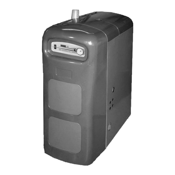
95M-200
GAS-FIRED DIRECT VENT
MODULATING HOT WATER BOILER
WARNING
!
Revise boiler control parameters only if you fully un-
derstand the purpose and result of the changes. Tam-
pering without understanding the control settings in
this manual will void the warranty and can result in
unreliable operation, with possible severe personal
injury, death, or substantial property damage.
WARNING
!
This document must only be used by a qualified
heating installer or service technician. Read all
instructions, including the Installation Manual
(P/N# 240006103), the Parameter Guide (P/N#
240006105), the User's Information Manual (P/N#
240006106), and this Control Manual and Oper-
ating Instructions before attempting to program
the control, and be sure to perform all steps in
the order specified. Failure to comply could re-
sult in severe personal injury, death, or substan-
tial property damage.
IMPORTANT: Installation must comply
with local requirements and with the Na-
tional Fuel Gas Code, ANSI Z223.1 for U.S.
installations or CSA B149.1 or B149.2 for
Canadian installations.
DO NOT DESTROY THESE INSTRUCTIONS!!
Please read carefully and keep in a safe place
for future reference.
P/N 240006104, Rev. A [05/08]
Advertisement
Table of Contents

Related Manuals for UTICA BOILERS 95M-200


Summary of Contents for UTICA BOILERS 95M-200
- Page 1 95M-200 GAS-FIRED DIRECT VENT MODULATING HOT WATER BOILER WARNING Revise boiler control parameters only if you fully un- derstand the purpose and result of the changes. Tam- pering without understanding the control settings in this manual will void the warranty and can result in unreliable operation, with possible severe personal injury, death, or substantial property damage.
-
Page 3: Table Of Contents
95-200M GAS FIRED DIRECT VENT MODULATING HOT WATER BOILER Control manual and oPerating instruCtions Printed in USA • Made In USA TABLE OF CONTENTS I - Safety Symbols and Warnings ....................3 II - Operating Information........................ 4 iii - modulating Control Features ....................6 iV - Boiler startup ........................... -
Page 4: Operating Information
II - OPERATING INFORMATION • Target temperature is determined by DHW HEATING: This boiler is controlled by a microprocessor electronic con- adding Parameter 1 to Parameter 33 (default 150°F and trol that senses outlet water temperature, return water tem- 30°F). Do not change Parameter 1 from the factory de- perature, and outdoor temperature (when a factory supplied, fault setting of 150°F unless the application is specially field installed outdoor sensor is installed). - Page 5 II - OPERATING INFORMATION Reset cuRve: The graph below shows how the boiler con- FREEZE PROTECTION trol calculates target temperature. Do not install the boiler in a room likely to freeze. • For outdoor temperature at or below 0°F, the target tem- NOTE: The following integral feature of the boiler control pro- perature equals Parameter 4 and never higher.
-
Page 6: Modulating Control Features
II - OPERATING INFORMATION immediately sets target outlet water temperature to 180°F. DHW OPERATION (IF USED) This provides automatic priority heat allocation to the indi- The boiler control allows connection of a DHW aquastat to rect water heater for maximum response and recovery. The low voltage terminal strip terminals DHW T1 and DHW T2. - Page 7 IV - BOILER STARTUP • When a summer/winter switch is used, closing the • Ignition. After prepurge, the control module [2180] switch will disable the boiler (space heating) circu- opens the gas valve and starts ignition spark. lator during summer operation. •...
- Page 8 IV - BOILER STARTUP Lower DHW aquastat to stop call for heat. Raise DHW aquastat above tank temperature to call for heat. • Postpurge. When room thermostat is satisfied • [1150] Blower/DHW circulator on. Blower and DHW cir- [5150] (call for heat ended), burner turns off. Blower will con- culator energize and control checks for air flow.
-
Page 9: Checkout Procedures And Adjustments
V - CHECKOUT PROCEDURES AND ADjUSTMENTS VERIFY SEqUENCE OF OPERATION TEST OTHER FIELD INSTALLED SAFETY CON- TROLS (IF USED) a detailed sequence of operation containing potential faults can be found in Sections VII, “Detailed Sequence of Opera- If the boiler is equipped with any additional safety controls, tion.”... - Page 10 V - CHECKOUT PROCEDURES AND ADjUSTMENTS Drill a ½” hole in the plastic CPVC vent pipe or exhaust Operate boiler for 5 minutes. tee, just large enough to allow access for the sample Turn off all other gas appliances, extinguishing standing probe of your combustion analyzer.
- Page 11 V - CHECKOUT PROCEDURES AND ADjUSTMENTS Pressure Guidelines Fan speed Minimum RPM Maximum RPM Fuel natural gas natural gas At least 10” gas line inlet At least 4” WC Pressure differential Pres- 0.3” WC 2.0” WC sure Note: Differential pressure values listed for comparison only. These values will change with vent length and altitude of installation.
-
Page 12: Detailed Sequence Of Operation
VI - DETAILED SEqUENCE OF OPERATION... -
Page 13: Vii- Service Hints
VII- SERVICE HINTS WARNING TROUBLESHOOTING TOOLS Have the following tools available prior to troubleshooting Do not attempt to modify the characteristics of your boiler: this boiler in any way!! Fire, explosion, or risk of shock hazard may cause property damage, •... -
Page 14: Troubleshooting
VIII - TROUBLESHOOTING WARNING DIFFERENTIAL AIR PRESSURE the differential air pressure switch is a safety device Electrical shock may cause serious injury or which will prevent the boiler from firing if there is an air death. The following procedures may expose intake, boiler heat exchanger or vent blockage. - Page 15 VIII - TROUBLESHOOTING WARNING WARNING Do not jumper fuse or replace with any fuse ex- Label all wires prior to disconnection when ser- cept as specified. Failure to comply could result vicing controls. Wiring errors can cause improp- in severe personal injury, death or substantial er and dangerous operation.
- Page 16 VIII - TROUBLESHOOTING Boiler Not Firing And: Check For: Step Corrective Actions: Control display blank 120 vac at terminals L1 and L2 of NO - Check external line switch and fuse or breaker. line voltage strip? 120 vac on both sides of fuse F1? NO - Turn off power to boiler and replace fuse if necessary.
- Page 17 VIII - TROUBLESHOOTING SOFT LOCKOUT (Display flashes “9” and then “b” in first position; last two digits on steady (code)) Corrective Actions (pressing RESET should restart boiler immediately): Code Reason For Soft Lockout WARNING: Electrical shock hazard. Turn off power to boiler when working with wiring or replacing any boiler component. High Limit Operation: Return temp.
- Page 18 VIII - TROUBLESHOOTING HARD LOCKOUT (Display flashes first digit “E” and last two digits (code)) Corrective Actions (pressing RESET should restart boiler immediately): Code Reason For Hard Lockout WARNING: Electrical shock hazard. Turn off power to boiler when working with wiring or replacing any boiler component. Flame detected on startup.
- Page 19 VIII - TROUBLESHOOTING HARD LOCKOUT (Display flashes first digit “E” and last two digits (code)) Corrective Actions (pressing RESET should restart boiler immediately): Code Reason For Hard Lockout WARNING: Electrical shock hazard. Turn off power to boiler when working with wiring or replacing any boiler component. Reset control and retry.
-
Page 20: User Interface Quick Reference
Ix - USER INTERFACE qUICK REFERENCE STANDBY MODE - KEY FUNCTIONS AND DISPLAY When boiler is powered on, the display will always show a single character (which represents the boiler’s current operating sequence) followed by the measured outlet water temperature during self-test. When entering Standby Mode, user Stby 0 180... - Page 21 Ix - USER INTERFACE qUICK REFERENCE PARAMETER MODE Press [MODE] button 1 time from Standby Mode. display shows Para until a key is Para 1 180 then displays Parameter and Current Status. pressed Press and Hold Key(s) in BLACK Duration Result Display step to next parameter (continue tapping...
- Page 22 Ix - USER INTERFACE qUICK REFERENCE HARD LOCKOUT MODE Boiler in hard lockout (requires manual RESET) Display flashes first digit E and last two digits (lockout code) (see below) Code Reason for hard lockout Code Reason for hard lockout Flame detected on start-up Supply water temperature higher than 200°F Ignition failed after 5 retries Return water temperature higher than 190°F...
- Page 24 For technical assistance with this product, in the United States call toll free 1-800-325-5479, and in Canada call toll free 1-888-270-8324. eCr international PO Box 4729 Utica, NY 13504-4729 www.ecrinternational.com...