Panasonic NN-CS894S Service Manual
Hide thumbs
Also See for NN-CS894S:
- Operating instructions manual (52 pages) ,
- Operating instructions manual (131 pages)

Related Manuals for Panasonic NN-CS894S


Summary of Contents for Panasonic NN-CS894S
-
Page 1: Microwave Oven
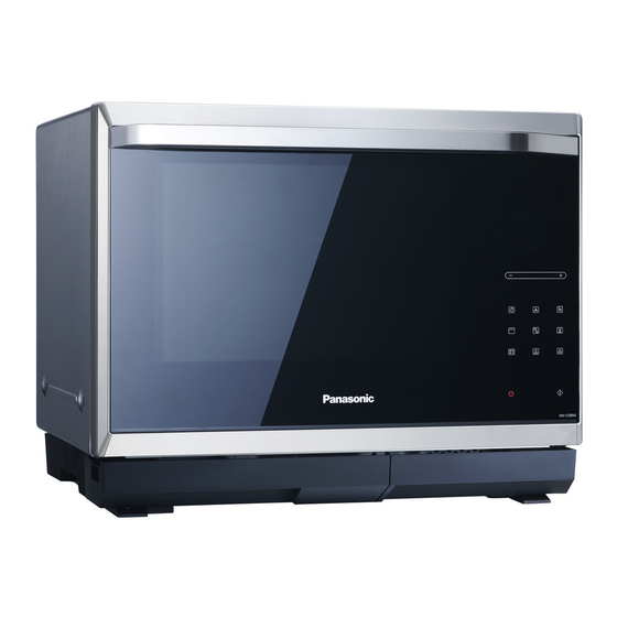
ORDER NO.PAPMOSH1312045CE Microwave Oven NN-CS894S BPQ (U.K.) EPG (Continental Europe) WPG (Switzerland) SPG (Norway, Finland, Sweden, Denmark) © Panasonic Appliances Microwave Oven (Shanghai) Co., Ltd. 2013. - Page 2 NN-CS894S...
- Page 3 NN-CS894S...
-
Page 4: Table Of Contents
NN-CS894S CONTENTS Page Page 1 SCHEMATIC DIAGRAM 4.7. Pump 2 DESCRIPTION OF OPERATING SEQUENCE 4.8. Front cover 2.1. Variable power cooking control 5 COMPONENT TEST PROCEDURE 2.2. Inverter power supply circuit 5.1. Primary, Secondary Latch Switch interlocks & Power 2.3. Turbo defrost, Auto cook Relay RY1 2.4. -
Page 5: Description Of Operating Sequence
NN-CS894S 2 DESCRIPTION OF OPERATING SEQUENCE 2.1. Variable power cooking 2.3. Turbo defrost, Auto cook control When the Auto Control feature is selected and the Start pad is tapped: High Voltage Inverter Power Supply (U) controls output power by the signal from Digital Programmer Circuit (DPC). Power 1. -
Page 6: Grill Cooking Control
NN-CS894S 2.6. Grill cooking control Grill cooking is accomplished by upper heaters only. One grill cooking cycle is 33 seconds. 1. During grill cooking, the digital programmer circuit controls power relay RY3´s ON-OFF time. In all three grill cooking categories, power relay RY1 always stay ON, but RY3´s ON-OFF time are shown in Figure. -
Page 7: Cautions To Be Observed When Troubleshooting
NN-CS894S 3 CAUTIONS TO BE OBSERVED WHEN TROUBLESHOOTING Unlike many other appliances, the microwave oven is a high WARNING DISCHARGE HIGH VOLATGE voltage, high current device. It is free from danger in ordinary CAPACITORS use, though extreme care should be taken during repair. -
Page 8: Confirm Before Repair
NN-CS894S 3.7. Verification after repair 3.4. Confirm before repair CAUTION CAUTION After repair or replacement of parts, make sure that all the water pipes To prevent the water from invading the electric parts that can cause a and tubes are properly connected, otherwise the water might invade short circuit or electric shock: the electric parts and will cause a short circuit or electric shock. -
Page 9: Disassembly And Parts Replacement Procedure
NN-CS894S 4 DISASSEMBLY AND PARTS REPLACEMENT PROCEDURE 4.1. Cabinet body & Rear cover B CAUTION Discharge the high voltage capacitors first to prevent electric shock. 1. Remove 2 screws holding exhaust guide on the oven cavity, and then remove exhaust guide. -
Page 10: Inverter/Magnetron/Digital Programmer Circuit (D
NN-CS894S 4. Remove left and right door key springs from door arm. 4.2. H.V. Inverter/Magnetron/Digital NOTE: programmer circuit (D.P.C.) Support door before removing door springs. (AU)/Fan motor/Stirrer motor 5. Disconnect the connector from convection fan motor 1. Discharge high voltage remaining in high voltage capacitor. - Page 11 NN-CS894S 4.2.1. To replace magnetron 4.2.2. To replace H.V Inverter 1. Release 4 catch hooks, then remove inverter cover. 1. Remove air guide D. 2. Remove 2 screws holding air guide F. 2. Remove 2 screws holding H.V. Inverter. 3. Remove 1 screw holding thermistor on magnetron.
- Page 12 NN-CS894S 4.2.3. To replace Digital programmer 4.2.4. Low voltage transformer and/or circuit D.P.C.(AU) board power relays CAUTION: CAUTION: Be sure to ground any static electric charge built up in Be sure to ground any static electric charge built up in your body before handling the D.P.C.
- Page 13 NN-CS894S 4.2.5. To replace fan motor 1. Disconnect connector of fan motor. 2. Remove 2 screws holding fan case (U) . 3. Remove 3 screws to seperate fan motor from fan case cover.
- Page 14 NN-CS894S 3. Disconnect connector from stirrer motor. 4.2.6. To remove stirrer motor 1. Remove 2 screws holding motor bracket. 4. Remove 2 screws holding stirrer motor on the motor bracket. 2. Pull out shaft from stirrer motor. To install stirrer motor 5.
-
Page 15: Upper Heater (Heater Bu)
NN-CS894S 4.3. Upper Heater (Heater BU) 4.4. Steam Heater (Heater DU) 1. Remove 4 screws holding left and right heater bracket on 1. Draw out water tank (U) from drip tray. oven cavity, then remove both 2 heater brackets. 2. After removing the water tank, select the "drainage"... -
Page 16: Door Assembly/Digital Programmer Circuit (D.p.c) (Fu)
NN-CS894S 6. Remove 3 screws holding steam heater on oven assy. 4.5. Door assembly/Digital programmer circuit (D.P.C) (FU) & (D.P.C) (BU) 1. Remove left and right door key springs from door arm with plier. NOTE: Support door before removing door springs. - Page 17 NN-CS894S 1. Release 2 catch hooks to turn out the harness protector´s 3. Disconnect 1 connector from D,P.C. (AU) board. cover horizontally from the right side of oven cavity. 4. Draw out harness protector slightly in direction of arrows. 2. Remove 1 screw holding harness protector on right hinge...
- Page 18 NN-CS894S 5. Release the catch hooks on harness protector to seperate 7. Remove 8 screws holding door E on door A (U). lead wire harness from harness protector. NOTE: After replacement of the defective component parts of the door, reassemble it properly and adjustment so as...
- Page 19 NN-CS894S 4.5.2. To replace D.P.C. (FU) board 4.5.3. To replace door screen B (U) 1. Remove 2 screws holding heat insulation panel. 1. Remove 6 screws holding door handle (U) on door A (U). 2. Remove 6 screws holding escutcheon base.
-
Page 20: Convection Motor And Convection Heater
NN-CS894S 4.5.4. To replace fan motor (BU) 4.6. Convection motor and convection heater 1. Release catch hooks and pull out fan motor (BU). 1. Remove 5 screws holding rear cover B. 2. Remove 2 screws from the convectin heater terminals. - Page 21 NN-CS894S 4. Disconnect the connectors from convection fan motor 7. Remove 2 screws holding convection module on base terminals and thermal cutout terminals. plate. 4.6.1. To replace convection heater 1. Remove 2 screws holding convection heater from convection fan cover.
-
Page 22: Pump
NN-CS894S 4.6.2. To replace convection fan motor 4.7. Pump 1. Remove 1 nut holding convection fan blade, then remove 1. Draw out water tank (U) from drip tray. convection fan blade. 2. After removing the water tank, select the "drainage"... - Page 23 NN-CS894S 6. Remove 1 screw fixing the cover of water tank holder. 8. The matching relationship between tank (U), pump motor and water tank holder are as the illustration below. 7. Release 2 locking tabs to open the cover.
-
Page 24: Front Cover
NN-CS894S To install pump motor 1. Insert pump motor into water tank holder. 2. Make sure that the pump motor is properly aligned after installation. NOTE: To prevent tube B from slipping out after repairing, make sure the insert depth should be proper when inserting tube B into nozzle A. -
Page 25: Component Test Procedure
NN-CS894S 5 COMPONENT TEST PROCEDURE 5.3. Magnetron WARNING 1. High voltage is present at the output terminals of the High Voltage Inverter (U) including aluminum heat sink during any cook cycle. Continuity checks can only indicate an open filament or a 2. -
Page 26: Inverter Power Supply (U)
NN-CS894S a. After approximately 3 seconds, oven stops operating. 5.5. Inverter power supply (U) b. During oven operation, input current DO NOT try to REPAIR H.V. Inverter power supply approximately 0.4A. (U).Replace complete H.V. Inverter(U) Unit. INPUT CURRENT FAILURE CODE Unplug CN701 0.4A... -
Page 27: Measurements And Adjustments
NN-CS894S 6 MEASUREMENTS AND ADJUSTMENTS 6.1. Adjustment of Primary latch switch, Secondary latch switch and Short switch. 1. Mount the Primary latch switch, the Secondary latch switch and the Short switch to the door hook assembly as shown in illustration. -
Page 28: Measurement Of Microwave Output
NN-CS894S 6.2. Measurement of microwave output The output power of the magnetron can be determined by performing IEC standard test procedures. However, due to the complexity of IEC test procedures, it is recommended to test the magnetron using the simple method outlined below. -
Page 29: Troubleshooting Guide
NN-CS894S 7 TROUBLESHOOTING GUIDE DANGER: HIGH VOLTAGES 1. DO NOT RE-ADJUST PRESET CONTROL on the H.V.Inverter (U). It is very dangerous to repair or adjust without proper test equipment because this circuit generates very large current and high voltage. Operating a misaligned inverter circuit is dangerous. -
Page 30: Troubleshooting) Other Problems
NN-CS894S 7.2. (Troubleshooting) Other problems SYMPTOM CAUSE CORRECTIONS 1. Oven is dead. 1. Open or loose lead wire harness Fuse is OK. 2. Open thermal cutout / thermistor Check thermal cutout is defective. No display and no operation at all. -
Page 31: Troubleshooting Of Inverter Circuit (U) And Magnetron
NN-CS894S 7.3. Troubleshooting of inverter circuit (U) and magnetron This oven is programmed with a self diagnostics failure code system which will help for troubleshooting. H95, H97, H98 and H99 are the provided failure codes to indicate magnetron and inverter circuit problem areas. This section explains failure codes of H95, H97, H98 and H99. -
Page 32: Simple Way Of H.v. Inverter/Magnetron Troubleshooting
NN-CS894S 7.4. Simple way of H.V. Inverter/magnetron troubleshooting Purpose: Simple way (3/23 seconds rule) of identifying whether it’s Magnetron, Inverter, or others. Set-up: The unit under question is connected through the Ammeter as shown below. Procedure: Follow the matrix table below to identify the problem source. -
Page 33: Inverter Main Parts List (Z606Ybh20Gp)
NN-CS894S 7.6. H.V. INVERTER MAIN PARTS LIST (Z606YBH20GP) Ref. No. Part No. Part Name & Description Pcs/Set Remarks Q701 Z1JAEV000003 IGBT C701 ZCWHC3B104JA FILM CAPACITOR 0.1µF,1000VDC C702 ZCWF4305N851 FILM CAPACITOR 3µF,250VDC DB701 Z0FBBQ000006 RECTIFIER BRIDGE L701 Z5020W100AP CHOKE COIL R702...