
Related Manuals for Mitsubishi WD-52327


Summary of Contents for Mitsubishi WD-52327
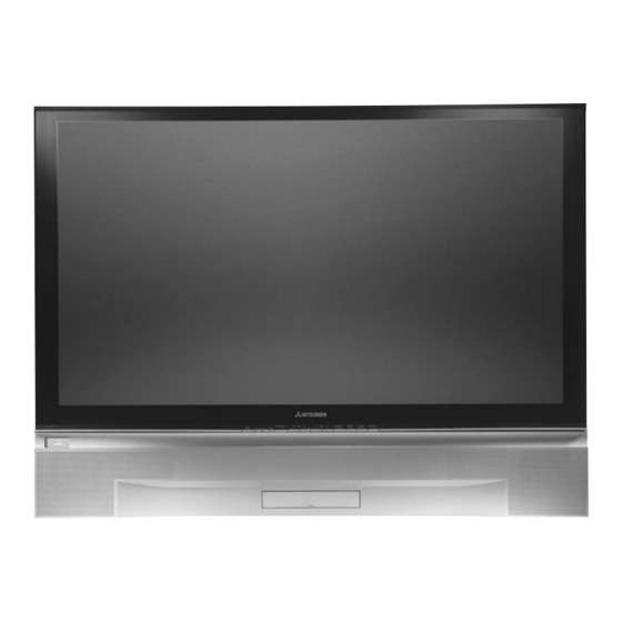
- Page 1 Owner’s Guide Owner’s Guide Projection Television Models WD-52327, WD-62327 visit our website at www.mitsubishi-tv.com...
- Page 2 • Consult the dealer or an experienced radio/TV technician for help. STAND REQUIREMENT CAUTION: Mitsubishi TV model WD-52327 is for use only with Mitsubishi stand, model MB-52525. Mitsubishi TV model WD-62327 is for use only with Mitsubishi stand model MB-62525. Use with other stands may result in instability causing possible injury.
-
Page 3: Table Of Contents
Chapter 1 Television Overview TV Accessories... 8 Special Features... 8 Front Control Panel ...9 Back Panel Input/Output... 10 Chapter 2 Connecting Antenna ... 12 Wall Outlet Cable... 12 Antenna to a Cable Box... 13 Antenna to a VCR ... 13 Antenna to a Cable Box and VCR ... -
Page 4: Important Safeguards
IMPORTANT SAFEGUARDS Please read the following safeguards for your TV and retain for future reference. Always follow all warnings and instructions marked on the television. 1. Read, Retain and Follow All Instructions Read all safety and operating instructions before operating the TV. Retain the safety and operating instructions for future reference. -
Page 5: Replacement Parts
IMPORTANT SAFEGUARDS, continued power circuits, or where it can fall into such power lines or circuits. When installing an outside antenna system, extreme care should be taken to keep from touching such power lines or circuits as contact with them might be fatal. - Page 6 Thank You for Your Purchase Welcome to the wonderful and exciting world of digital television! We are honored that you chose Mitsubishi as your premier home entertainment partner. The development team at Mitsubishi Digital Electronics America (MDEA) understands that our customers demand and expect the very best. MDEA was founded on the core beliefs and philosophies that drive us to deliver products that implement the latest in advanced television technology.
- Page 7 Chapter Television Overview TV Accessories ... 8 Special Features ... 8 Front Control Panel... 9 Back Panel Input/Output ... 10...
-
Page 8: Tv Accessories
TV Accessories Please take a moment to review the following list of items to ensure that you have received everything including: CABLE/DBS/DTV AUDIO POWER SLEEP VIDEO INPUT CHANNEL VOLUME AUDIO MUTE ENTER HOME EXCH ADJUST CANCEL MENU INFO V-CHIP PIP CH PIP INPUT GUIDE FORMAT... -
Page 9: Front Control Panel
Front Control Panel The buttons on the Front Control Panel highlighted in gray are duplicated on the remote control. The top row of labels show the control functions when there are no TV menus displayed on the screen. The bottom row of labels show the control functions when the TV menus are displayed on the screen or when a special function has been activated. -
Page 10: Back Panel Input/Output
Back Panel Input/Output I N P U T A N T - A 1. ANT-A, LOOP OUT and ANT-B ANT-A and ANT-B receive signals from VHF/UHF antennas or a cable system. LOOP OUT sends the ANT-A signal out to another device, such as a cable box or VCR. Note: LOOP OUT is disabled when Energy Mode is set to Low and the TV power is set to Off. -
Page 11: Connecting
Connecting Antenna... 12 Wall Outlet Cable ... 12 Antenna to a Cable Box... 13 Antenna to a VCR ... 13 Antenna to a Cable Box and VCR... 14 Composite Video or S-Video (Recommended) with Audio... 14 Stereo Audio System ... 15 Audio Receiver ... -
Page 12: Antenna
Connecting an Antenna or Wall Outlet Cable Separate UHF and VHF Antennas (Figure 1) 1. Connect the UHF and VHF antenna leads to the UHF/VHF combiner. 2. Push the combiner onto ANT-A on the TV back panel. UHF/VHF combiners are not provided with the TV. They are available at most electronic stores. -
Page 13: Antenna To A Cable Box
Connecting an Antenna to a Cable Box or VCR Antenna to a Cable Box (Figure 3) 1. Connect the incoming cable to ANT-A on the TV back panel. Connect two coaxial cables as follows: 2. One from LOOP-OUT on the TV back panel to IN on the cable box back panel. -
Page 14: Antenna To A Cable Box And Vcr
Connecting an Antenna to a Cable Box and VCR, Connecting Composite Video or S-Video with Audio Contact your local cable or satellite provider or refer to the cable box or satellite Owner’s Guide for instructions on optimal connections to this TV. Antenna to Cable Box and VCR (Figure 5) 1. -
Page 15: Stereo Audio System
Connecting a Stereo Audio System Conecting an Audio Receiver Stereo Audio System (Recommended for shelf units or A/V receivers without digital audio inputs) (Figure 7) 1. Connect the audio cables from AUDIO MONITOR OUTPUT on the TV back panel to TV IN or AUX IN terminals on the back of the audio system. -
Page 16: Dvd Player
Connecting a DVD Player or Other S-Video Device DVD Player with Component Video (Recommended) (Figure 9) 1. Connect the Component Video cables from (YCb Cr or Y Pb Pr) VIDEO OUT on the back of the DVD player to COMPONENT (1 or 2) on the TV back panel. -
Page 17: Dtv Receiver
Connecting a DTV Receiver Contact your local cable or satellite provider or refer to the cable box or satellite Owner’s Guide for instructions on optimal connections to this TV. DTV Connectors and Adaptors (Figure 11) The TV back panel has 5 RCA-type connectors for the DTV connection. - Page 18 Connecting a DTV Receiver, continued DTV Receiver with RGB Video Connections (Figure 13) 1. Connect the outside antenna, cable, or satellite to ANT or SATELLITE IN on the DTV receiver (see your DTV receiver owner’s guide for instructions and cable compatibility). 2.
-
Page 19: Monitorlink/Dvi
Connecting MonitorLink™/DVI MonitorLink/DVI (Figure 14) The Monitor Link/DVI input uses a DVI-I Dual Link connector for maximum cable flexibility. When MonitorLink is used as a DVI-HDCP input, the terminal is compliant with DVI-D Single Link signals matching EIA-861 standards for standard, extended and high definition video with scanning rates of 480p and 1080i. -
Page 20: How Connections Affect The Pip And Pop
How Connections Affect the PIP (Picture-In-Picture) and POP (Picture-Outside-Picture) To see a picture in the PIP or POP, you may need to select an input source. If the only input connected is ANT-A, then both the main picture and the PIP/POP will be from that input source. If other video equipment is connected, you may be able to view these input sources as the PIP/POP. - Page 21 Chapter Remote Control Functions Overview of the TV Layer Buttons ... 22 Care and Operation ... 23 Channel Selection... 24 Sleep Timer ... 24 Use With Other A/V Products... 25 Special Functions ... 27 Operation of PIP and POP... 28...
-
Page 22: Overview Of The Tv Layer Buttons
Remote Control Functions: Overview (Figure 1, following page,) 1. Slide Switch: Select A/V product to be controlled by the remote control. 2. Numbers: Individually select channels or input information into TV. 3. POWER: Turns power on and off for TV and other connected A/V products. -
Page 23: Care And Operation
Remote Control Functions: Care and Operation Operation Installing the Batteries: (Figure 2) 1. To remove the back battery cover, gently press the ridged tab in the direction of the arrow and slide the cover off. 2. Load the batteries, making sure the polarities (+) and (-) are correct. -
Page 24: Channel Selection
Remote Control Functions: CABLE/DBS/DTV AUDIO Figure 3. Sleep button on remote control Sleep: 30 min. Figure 4. On-screen display for sleep timer Channel Selection, Sleep Timer Channel Selection • Enter three numbers (for channel 2, press 002). • Press the channel number and ENTER (for channel 2, press 2, then ENTER). -
Page 25: Use With Other A/V Products
Use of the Remote Control with Other A/V Products Programming the Remote Control to Use with Other Brands of Audio and Video Products: (Figures 1-4 this page, Figure 5, following page) 1. Move the slide switch at the top of the remote to the product you want to control. 2. - Page 26 Use of the Remote Control with Other A/V Products, continued CABLE/DBS/DTV AUDIO A/V Receiver Codes Audio brand Code to enter: Mitsubishi A/V receiver 010, 015, 011, 012, and/or CD player 013, 014 234, 235, 236, 245, Denon 246, 359 Harman Kardon 215, 223, 242 233, 232 Kenwood...
-
Page 27: Special Functions
Remote Control Functions: Special Functions When your remote control has been programmed to operate another manufacturer’s product, the function performed on each layer may vary. The most common functions are: • POWER • CHANNEL up/down • PLAY • REC • PAUSE •... -
Page 28: Operation Of Pip And Pop
Remote Control Operation of PIP and POP Picture-In-Picture (PIP) and Picture-Outside- Picture (POP) features allow you to view programming in different ways. While watching the main screen, you can display programs from other channels and other inputs. To see which inputs can and cannot be used together, see How Connections Affect the PIP and POP, page 20. You can display large and small PIPs, side-by-side pictures, three POPs, or nine POPs. -
Page 29: Chapter 4 Menu Screen Operations
Chapter Menu Screen Operations The ViewPoint® Menu System ... 30 MAIN Menu ... 31 SETUP Menu... 33 CAPTIONS Menu ... 37 CHANNEL EDIT Menu... 39 V-CHIP LOCK Menu ... 42 ADVANCED FEATURES Menu... 46 AUDIO/VIDEO SETTINGS Menu ... 50... -
Page 30: The Viewpoint® Menu System
Menu System Mitsubishi’s exclusive system provides on-screen information for menu choices and changes. A picture (icon) will be highlighted and can be selected using the remote control’s ADJUST arrows. When selected, the appropiate menu will appear or start an automatic function. You may then make changes within the menu or access available sub- menus. -
Page 31: Main Menu
Main Menu Screens: Overview SETUP Menu (Figure 3) Basic (initial) setup instructions and functions are available through the SETUP submenu screens. Use this menu when you relocate the TV, experience a power loss or when devices are added after initial setup. - Page 32 Main Menu Screens: Overview, continued V-CHIP LOCK Menu (Figure 6) Lock the TV by selecting times, setting the Front Button Lock or choosing programs to block based on rating signals sent by your local broadcasting system. See pages 42-45 for detailed setup information. See page 42 for V-Chip rating information.
-
Page 33: Setup Menu
SETUP Menu: Memorize Channels, Memorize Menu, Input Assignment Memorize Channels (Figure 9) Select Memorize Channels for each antenna you use. The TV will find and remember strong channels and skip the unused or weaker channels. MAIN MENU SETUP menu Memorize Channels : Ant A INPUT ASSIGNMENT CLOCK... - Page 34 SETUP Menu: Manually Setting the Clock Clock Setting (Manual) (Figure 12) The Clock Setting menu default allows the clock time to be set manually. To set the clock automatically, please see page 35. To set the clock manually, first select the current time, including AM or PM.
- Page 35 SETUP Menu: Automatically Setting the Clock Clock Setting (Auto) (Figure 14) Set the Clock Setting to Auto to automatically set the day and time using Extended Data Service (XDS) time data. This data is automatically retrieved when tuned to a PBS channel or other channel in your area that provides this service.
-
Page 36: Energy Mode
SETUP Menu: Language, Energy Mode Language (Figure 17) Display the on-screen menus in either English or Spanish (Español). The first time you powered On your TV, you were requested to select an on-screen menu language. If you choose to change the selection, all menu text will immediately switch to the language of your choice. -
Page 37: Captions Menu
CAPTIONS Menu: Overview CAPTIONS Menu (Figure 20) Turn On or Off the closed caption decoder, select the type of captions or text, and choose black or translucent gray as the background color for the closed caption area. Broadcasters can send either Standard or Text closed captioning. -
Page 38: Closed Captions
CAPTIONS Menu: Closed Captions, Background Color Closed Captions (Figure 21) Display one of the following types of Closed Captions: CC1, CC2, CC3, or CC4: Standard closed captioning signals. Text1, Text2, Text3, or Text4: Text closed captioning signals. On if mute: Closed captions when mute. When selected, the standard closed captioning signal (CC1) will turn on/off by pressing the MUTE button on the TV remote control. -
Page 39: Channel Edit Menu
CHANNEL EDIT Menu: Antenna, Channel Selection Antenna (Figure 23) Select Ant-A or Ant-B. For each antenna, you can add or delete channels in memory, name channels, and add channels to the SQV (SuperQuickView™) list. MAIN MENU CHANNEL EDIT menu ANTENNA : Ant A Channel : 003... - Page 40 CHANNEL EDIT Menu: Memory, Name Selection Memory (Figure 25) Add weaker channels viewed with Ant-A or Ant-B and delete unwanted channels, after all available channels have been memorized with Memorize Channels (page 33). Use the CHANNEL button on the remote control to view memorized channels.
-
Page 41: Super Quick View
CHANNEL EDIT Menu: Using SQV SQV Using The Menu Screen (Figure 27) Put together a list of your favorite channels from Ant-A and Ant-B using SQV (SuperQuickView™). Store up to 6 channels in each of the 9 different memory banks. After adding a channel to the SQV memory, “SQV”... -
Page 42: V-Chip Lock Menu
V-Chip Lock Menu: Overview V-Chip Signal Information When provided by the broadcaster, V-Chip ratings can be used to control which programs can be viewed or will be blocked. When V-Chip ratings are sent, you will see the ratings when you change the channel or when you press the INFO button on the remote control. - Page 43 V-CHIP Menu: Setting Up and Using V-Chip Lock Passcode Setting Up the V-CHIP LOCK Passcode (Figure 29) Select V-CHIP LOCK from the MAIN menu for first time setup or after you have canceled your passcode. You will see the screen shown in Figure 29. Use the number buttons on the remote control to input a new four-digit passcode, then press ENTER.
-
Page 44: Lock By Time
Locking by Time, Front Button Lock, V-Chip V-CHIP Menu: Rating Menu LOCK by Time (Figure 33) Select On at Lock by Time, then select the Lock Time and Unlock Time. This will lock the entire TV. Your TV continues to be locked until you input your passcode, or when the locked time expires. - Page 45 V-CHIP Menu: Allowing or Blocking Ratings, Lock by Time Allowing or Blocking by Ratings (Figure 36) Block or Allow programs based upon rating signals sent by the broadcasting station. The factory preset for TV Ratings is TV-PG (Parental Guidance) allowing only programs rated TV-PG or lower.
-
Page 46: Advanced Features Menu
ADVANCED FEATURES Menu: Color Balance, Auto Color Correction, PerfectColor ™, Reset Color Color Balance Menu (Figure 38) The Color Balance Menu uses six colors (Magenta, Red, Yellow, Green, Cyan and Blue). You may adjust the intensity of these colors automatically or manually or reset them to the default settings. -
Page 47: Timer Menu
ADVANCED FEATURES Menu: TIMER, Timer Menu, and Set Time TIMER (Figure 41) The timer will automatically turn the TV on (if it is off) at the time you schedule and select. When Ant-A or Ant-B is the selected input, you may select any memorized channel. - Page 48 ADVANCED FEATURES Menu: Set Day, Input, and Channel Set Day (Figure 44) Select the days that the TV will turn on automatically. You can select Everyday, Mon-Fri (Monday through Friday), or the individual days of the week. MAIN MENU ADVANCED FEATURES MENU TIMER menu Timer : Off...
- Page 49 ADVANCED FEATURES Menu: Video Mute, Black Enhancement Video Mute (Figure 51) Video Mute, (when On) lets you display a blue background when no signal is being received on Inputs 1-3, DTV, Component 1-2 and MonLink. MAIN MENU ADVANCED FEATURES menu COLOR BALANCE TIMER Video Mute...
-
Page 50: Audio/Video Settings Menu
AUDIO/VIDEO SETTINGS Menu: Overview AUDIO/VIDEO SETTINGS Menu (Figure 53) Each input has its own A/V memory. You can adjust each input’s A/V memory in two ways. You can use the menu or the remote control. MAIN MENU AUDIO/VIDEO SETTINGS menu AV Memory Reset TV Speaker (Internal) -
Page 51: Audio Settings
AUDIO/VIDEO Setting Descriptions: Audio Audio Settings Bass • Enhances or reduces low frequency sound. • Treble Enhances or reduces high frequency sound. • Balance Adjusts the level of sound between the left and right speakers. Surround • Creates simulated stereo and surround effects. Your choices are: Off: No surround effects. -
Page 52: Video Settings
AUDIO/VIDEO Setting Descriptions: Video Video Settings A compressed (non-HD) video signal may cause what appears to be a “blurry”, “out of focus” or “fuzzy “ picture on a widescreen TV. This is not a malfunction of the TV, but a result of the compressed signal that is sent by cable or satellite. - Page 53 Chapter PIP/POP Operations Available On-Screen Format Sizes ... 54 Operation of PIP and POP... 56 Appendix A: Bypassing the V-Chip Lock... 57 Appendix B: HD Input Connection Compatibility ... 59 Appendix C: Remote Control Programming Codes ... 60 Appendix D: Cleaning and Service ... 62 Appendix E: Cleaning the Dust Filter...
-
Page 54: Available On-Screen Format Sizes
Available On-Screen Format Sizes Note: You can find aspect ratios on the back of most DVD covers. Also, Anamorphic DVDs are usually marked “Anamorphic” or “Enhanced for 16:9 TVs.” Format (picture shape) availability based on Input/Signal Expand INPUTS Standard 480i/480p Ant-A 000 Ant-B 000 DTV (480i/480p) - Page 55 Available On-Screen Format Sizes, continued Widescreen Picture (16:9 - HD 1080i only) Example: A True HD Broadcast Standard (Recommended) Widescreen Picture (480i/480p) Standard (Recommended) Zoom (For letterbox 2.35:1 DVDs) Stretch Plus HD Expand (Recommended for 4:3 images with Black Side Bars) Expand Stretch Narrow (Not Recommended)
-
Page 56: Operation Of Pip And Pop
Operation of PIP and POP Picture Inside Picture (PIP) vs. Picture Outside Picture (POP) You have the option to view two TV shows or inputs at the same time. For example, you can watch a game show and a sports event on another channel, or a DVD movie and more. The PIP option allows you to view another input as a picture-inside-picture. -
Page 57: Appendix A: Bypassing The V-Chip Lock
Appendix A: Bypassing the V-Chip Lock When changing or deleting your passcode, you must use the remote control included with this TV. You cannot use a Mitsubishi remote control from another component or a “universal” remote. Bypassing the V-Chip Lock After you set the lock, you need your passcode to view a V-Chip locked program, view the locked TV, cancel the lock, or enter the V-Chip lock menus. - Page 58 This page intentionally blank...
-
Page 59: Appendix B: Hd Input Connection Compatibility
Appendix B: High Definition Input Connection Compatibility Component Inputs These inputs are compatible with most standard DVD and DTV signals with component video outputs. Compatible DTV signals are SDTV 480i, 480p, and HDTV 1080i. All other DTV signals, such as 720p, need to be converted by the DTV receiver (or compatible device) to one of the compatible signal types. -
Page 60: Appendix C: Remote Control Programming Codes
Appendix C: Remote Control Programming Codes A/V Receivers Mitsubishi ... 010, 011, 012, 013, 014, 360 Admiral ... 220 Aiwa... 225, 226, 241 B & K ... 352 Bose... 351 Denon ... 234, 235, 236, 245, 246, 359, 361 Fisher ... 204 Gerrard... - Page 61 Appendix C: Remote Control Programming Codes, continued Satellite Receivers /DBS/DTV MitsubishiHD/Satellite Receiver ... 006, 173 Echostar/ Dishnetwork... 175, 82, 183, 188 Express Vu... 175 GE ... 176 Gradient ... 186 Hitachi... 173, 181, 184 Hughes... 173 Maganavox ... 171, 172 Panasonic ...
-
Page 62: Appendix D: Cleaning And Service
Appendix D: Cleaning and Service Cleaning Normally, light dusting with a dry, non-scratching duster will keep your TV clean. If cleaning beyond this is needed, please use the following guidelines: First, turn off the TV and unplug the power cord from the power outlet. Top and Sides of the TV: •... -
Page 63: Appendix E: Cleaning The Dust Filter
Appendix E: Cleaning the Dust Filter Cleaning the Dust Filter Clean the filter annually and whenever you replace the lamp cartridge. Tools needed: Phillips screwdriver 1. Turn the television off and unplug the AC cord. 2. Locate the dust filter on the left side panel of the TV. -
Page 64: Appendix F: Lamp Cartridge Replacement
Appendix F: Lamp Cartridge Replacement Before you replace the lamp cartridge please note the following: CAUTION: If the television is on, press POWER to turn off and allow the television to cool for one hour before attempting to replace the lamp cartridge. LAMP LIFE The light source for this television is a lamp, which is part of a lamp cartridge assembly. - Page 65 Appendix F: Lamp Cartridge Replacement Replacing the Lamp Cartridge Tool needed: Phillips screwdriver 1. Turn the television off and unplug the AC cord. 2. Remove the front speaker grill by gently pulling on each side. The grill will snap out. 3.
-
Page 66: Troubleshooting
Troubleshooting Problem The TV remote control does not work. The TV takes several seconds to respond to channel commands. You cannot access a channel. On-screen displays appear each time you change a function. The TV cannot be programmed to turn on automatically. -
Page 67: Additional Information
Troubleshooting, continued There is no picture when using MonitorLink/DVI input with an HDTV receiver or DVD player. No picture displays when using component inputs. V-Chip is not working. Cannot set adjustments to factory setting. Additional Information LICENSOR’S SUPPLIERS DO NOT MAKE OR PASS ON TO END USER OR ANY OTHER THIRD PARTY, ANY EXPRESS, IMPLIED OR STATUTORY WARRANTY OR REPRESENTATION ON BEHALF OF SUCH SUPPLIERS, INCLUDING, BUT NOT LIMITED TO THE IMPLIED WARRANTIES OF NON-INFRINGEMENT, TITLE, MERCHANTABILITY OR FITNESS FOR A PARTICULAR PURPOSE. -
Page 68: Index
Index Memory Reset 50 Receiver, Connecting 15 Activating the PIP and POP 28 Advanced Features Menu 32, 46-49 Antenna Channel Edit Menu 39-40 Connecting 12, 13, 14 Appendices A: Bypassing the V-Chip Lock 57 B: High Definition Input Connection Compatibility 59 C: Remote Control Programming Codes 60-61 D: Cleaning and Service 62 E: Cleaning the Dust Filter 63... -
Page 69: Index
Setup 33-36 V-Chip Lock 42-45 MonitorLink, Connecting 19 Moving PIP Images 56 Name Menu 40 PerfectColor™ 46 PIP and POP Activating 28 Changing 56 Freezing 56 How Connections Affect 20 Operation 56 POP “Live” Image, Selecting 56 Remote Control Functions Channel Selection 24 Operation 23 PIP and POP 28... - Page 70 Notice. To obtain warranty service, you must notify an authorized MITSUBISHI service center of any defect within the applicable warranty time period. e. This DLP™ Projection Television uses a revolutionary technology, Digital Micromirror Device™, to create the screen image. This technology creates the image using small dots, or picture elements (pixels). Your DLP Projection TV is manufactured to a high level of performance and quality, in fact, 99.99% perfect in the number of properly functioning pixels.
-
Page 71: Warranty
c. Proof of purchase date from an authorized MITSUBISHI dealer is required when requesting warranty service. Present your sales receipt or other document which establishes proof and date of purchase. THE RETURN OF THE OWNER REGISTRATION CARD IS NOT A CONDITION OF WARRANTY COVERAGE. However, please return the Owner Registration Card so that we can contact you should a question of safety arise which could affect you. - Page 72 If you have questions that cannot be answered from this book, please call our Consumer Relations advisors at (800) 332-2119 or send an email to: MDEAservice@mdea.com To order replacement remote controls, an Owner’s Guide or lamp cartridge, please call our Parts Department at (800) 553-7278 or contact us through our web site at: www.Mitsubishi-tv.com ©...