Table of Contents
Advertisement
AIR CONDITIONER
INSTALLATION MANUAL
OUTDOOR UNIT
For authorized service personnel only.
INSTALLATIONSANLEITUNG
AUSSENGERÄT
Nur für autorisiertes Fachpersonal.
MANUEL D'INSTALLATION
APPAREIL EXTÉRIEUR
Pour le personnel d'entretien autorisé uniquement.
MANUAL DE INSTALACIÓN
UNIDAD EXTERIOR
Únicamente para personal de servicio autorizado.
MANUALE DI INSTALLAZIONE
UNITÀ ESTERNA
A uso esclusivo del personale tecnico autorizzato.
ΕΓΧΕΙΡΙΔΙΟ ΕΓΚΑΤΑΣΤΑΣΗΣ
ΕΞΩΤΕΡΙΚΗ ΜΟΝΑΔΑ
Μόνο για εξουσιοδοτημένο τεχνικό προσωπικό.
MANUAL DE INSTALAÇÃO
UNIDADE EXTERIOR
Apenas para pessoal de assistência autorizado.
РУКОВОДСТВО ПО УСТАНОВКЕ
ВНЕШНИЙ МОДУЛЬ
Только для авторизованного обслуживающего персонала.
MONTAJ KILAVUZU
DIŞ ÜNİTE
Yalnızca yetkili servis personeli için.
PART No. 9379069403
Advertisement
Table of Contents

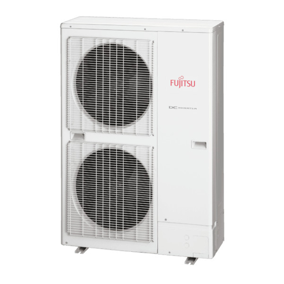
Summary of Contents for Fujitsu AOYG60LATT
-
Page 1: Air Conditioner
AIR CONDITIONER INSTALLATION MANUAL OUTDOOR UNIT For authorized service personnel only. INSTALLATIONSANLEITUNG AUSSENGERÄT Nur für autorisiertes Fachpersonal. MANUEL D’INSTALLATION APPAREIL EXTÉRIEUR Pour le personnel d’entretien autorisé uniquement. MANUAL DE INSTALACIÓN UNIDAD EXTERIOR Únicamente para personal de servicio autorizado. MANUALE DI INSTALLAZIONE UNITÀ... -
Page 2: Table Of Contents
INSTALLATION MANUAL WARNING OUTDOOR UNIT PART No. 9379069403 English Installation work must be performed in accordance with national wiring standards by authorized personnel only. Contents Do not use this equipment with air or any other unspecifi ed refrigerant in the refrigerant lines. -
Page 3: About The Unit
2. ABOUT THE UNIT 2.3. Accessories WARNING 2.1. Precautions for using R410A refrigerant For installation purposes, be sure to use the parts supplied by the manufacturer or other prescribed parts. The use of non-prescribed parts can cause serious accidents such as WARNING the unit falling, water leakage, electric shock, or fi... -
Page 4: Drain Installation
CAUTION CAUTION Install the outdoor unit in a location that is away from exhaust or the vent ports that Observe the installation space specifi cations that are shown in the fi gures. discharge vapor, soot, dust, or debris. Keep the same space at rear air intake. Provide the same space for the air intake at the rear of the outdoor unit. -
Page 5: Transporting The Unit
Fig. B (3) Obstacles at front and rear only 1500 or more Front view Rear view When an obstruction is present also in the upward area (Unit : mm) Obstacles at rear and above only 3.5. Installation (Unit : mm) 1500 1500 Max. -
Page 6: Protection Of Pipes
Fig. A Thicknesses of Annealed Copper Pipes (R410A) Pipe outside diameter Thickness [mm] [mm (in.)] 6.35 (1/4) 9.52 (3/8) 12.70 (1/2) 15.88 (5/8) 19.05 (3/4) 4.2. Protection of pipes Service panel Protect the pipes to prevent the entry of moisture and dust. Especially, pay attention when passing the pipes through a hole or connecting the end of a pipe to the outdoor unit. -
Page 7: Sealing Test
5.3.1. Flaring • Outer panel may be distorted if fastened only with a wrench. Be sure to fi x the elementary part with a spanner and fasten with a wrench (refer to below diagram). Use special pipe cutter and fl are tool exclusive for R410A. •... -
Page 8: Vacuum Process
CAUTION 5.5. Vacuum process When charging the refrigerant, take into account the slight change in the composition of the gas and liquid phases, and always charge from the liquid phase side whose composition is stable. Adding refrigerant through the gas pipe will cause a malfunction. CAUTION Check if the steel cylinder has a siphon installed or not before fi... -
Page 9: Selecting Circuit Breaker And Wiring
(6) See the table below for the terminal screw tightening torques. WARNING [N·m (kgf·cm)] Tightening torque Do not modify power cable, use extension cable or branch wiring. Improper use may M4 screw 1.2 to 1.8 (12 to 18) cause electric shock or fi re by poor connection, insuffi cient insulation or over current. M5 screw 2.0 to 3.0 (20 to 30) Connect the connector cable securely to the terminal. -
Page 10: Wiring Method
(3) Secure the cables using the cable clips under the terminal blocks, and then secure 6.4. Wiring method the cables using the cable clips attached to the base of the valves. 6.4.1. Connection diagrams POWER SUPPLY EARTH (GROUND) Control line Cable clip Power line Earthing (Grounding) line... -
Page 11: How To Operate Display Unit
8. HOW TO OPERATE DISPLAY UNIT 8.2. Description of display Function or operation method Display lamp 8.1. Various setting methods Lights on while power on Local setting in (1) POWER/MODE Green outdoor unit or error code is displayed with blink. WARNING Blinks during abnormal air-conditioner (2) ERROR... -
Page 12: Peak Cut Mode (Local Work)
9.1.1. Setting for low noise 9.2. Peak cut mode (Local work) LED display part Effi cient operation while reducing power supply and power consumption with below local work. • Peak cut function can be effective with contact installation of an additional ON-OFF switch to the CN19 connector on the outdoor control board. -
Page 13: Test Run
(6) Press ENTER switch (SW4) and fi x it. (3) Press ENTER (TEST RUN) switch for more than 3 seconds. TEST PUMP POWER PEAK CUT LOW NOISE PEAK CUT DOWN ERROR MODE (L5) (L6) (L7) (L1) (L2) (L3) (L4) (L5) (L6) (L7) 0% of rated input ratio... -
Page 14: Preparation For Pump Down
(6) LED display changes after 1 minute as shown in the fi gure below. TEST PUMP POWER LOW NOISE PEAK CUT DOWN ERROR MODE (L1) (L2) (L3) (L4) (L5) (L6) (L7) Reactors Terminal blocks Fans and compressor stop automatically. If the pump down is successfully completed (the above LED display is shown), the outdoor unit remains stopped until the power is turned off. -
Page 15: Error Code Check Table
12.2. Error code check table TEST PUMP POWER LOW NOISE PEAK CUT DOWN ERROR Description MODE (L1) (L2) (L3) (L4) (L5) (L6) (L7) Serial forward transmission error immediately after operation Serial forward transmission error during operation Indoor unit capacity error (15) Indoor unit error Over voltage...


