Table of Contents
Advertisement
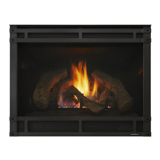
Models:
7000TR
6000TRB
6000SEB
WARNING: IF THE INFORMATION
IN THESE INSTRUCTIONS IS NOT
FOLLOWED EXACTLY, A FIRE OR
EXPLOSION MAY RESULT CAUS-
ING PROPERTY DAMAGE, PER-
SONAL INJURY, OR DEATH.
Printed in U.S.A. Copyright 2000,
Heat-N-Glo, a division of Hearth Technologies Inc.
20802 Kensington Boulevard, Lakeville, MN 55044
This product is covered by one or more of the following patents: (United States) 4,112,913; 4,408,594; 4,422,426; 4,424,792; 4,520,791; 4,793,322;
4,852,548; 4,875,464; 5,000,162; 5,016,609; 5,076,254 5,191,877; 5,218,953; 5,328,356; 5,429,495; 5,452,708; 5,542,407; 5,613,487; (Australia)
543790; 586383; (Canada) 1,123,296; 1,297,746; 2,195,264; (Mexico) 97-0457; (New Zealand) 200265; or other U.S. and foreign patents pending.
GUIDE
WARNING: IMPROPER INSTALLA-
TION, ADJUSTMENT, ALTERATION,
SERVICE OR MAINTENANCE CAN
CAUSE INJURY OR PROPERTY DAM-
AGE. REFER TO THIS MANUAL. FOR
ASSISTANCE OR ADDITIONAL INFOR-
MATION CONSULT A QUALIFIED IN-
STALLER, SERVICE AGENCY, OR THE
GAS SUPPLIER.
1. This appliance may be installed in an af-
termarket, permanently located, manufac-
tured (mobile) home, where not prohibited
by local codes.
2. This appliance is only for use with the type
of gas indicated on the rating plate. This
appliance is not convertible for use with
other gases, unless a certified kit is used.
Please contact your Heat-N-Glo dealer for any
questions or concerns. For the number of your
nearest Heat-N-Glo dealer, please call 952-985-6000.
1
Installers Guide
Underwriters
Laboratories Listed
INSTALLERS
Advertisement
Table of Contents

Related Manuals for Heat-N-Glo 7000TR


Summary of Contents for Heat-N-Glo 7000TR
- Page 1 Printed in U.S.A. Copyright 2000, Please contact your Heat-N-Glo dealer for any questions or concerns. For the number of your Heat-N-Glo, a division of Hearth Technologies Inc.
-
Page 2: Safety And Warning Information
SAFETY AND WARNING INFORMATION These units MUST use one of the vent systems READ and UNDERSTAND all instructions carefully described in the Installing the Fireplace section of before starting the installation. FAILURE TO the Installers Guide. NO OTHER vent systems or FOLLOW these installation instructions may result components MAY BE USED. -
Page 3: Table Of Contents
Appliance Certification..............10 Installation Codes ................ 10 High Altitude Installations ............. 10 Section 2: Getting Started ............11 Introducing the Heat-N-Glo Gas Fireplaces ......... 11 Pre-installation Preparation ............11 Section 3: Installing the Fireplace .......... 13 Step 1 Locating the Fireplace ..........13 Step 2 Framing the Fireplace.......... -
Page 4: Section 1: Approvals And Codes
Approvals and Codes High Altitude Installations Appliance Certification Installers Guide Certification Installation Codes Heat-N-Glo Quality Systems registered by SGS ICS... -
Page 5: Section 2: Getting Started
Getting Started Introducing the Heat-N-Glo Gas Fireplaces Installers Guide Pre-install Preparation Installers Guide... - Page 6 36 1/8 [916mm] 10 1/4 [259mm] 41 1/8 6 7/8 [174mm] [1044mm] TOP STANDOFFS TOP VENT COLLARS REAR VENT COLLARS HOOD TRIM DOOR RATING PLATE LINE AND LABELS ACCESS ELECTRICAL ACCESS CONTROLS Figure 1. Diagram of the 7000TR, 6000TRB and 6000SEB.
-
Page 7: Section 3: Installing The Fireplace
Installing the Fireplace Step 1. Locating the Fireplace 1” MIN. (25mm) Vertical Sections Horizontal Sections 1/2” MIN. (13mm) 42” 22” 36” 51” 72” At Wall Firestops... -
Page 8: Step 2 Framing The Fireplace
Step 2. Framing the Fireplace CAUTION: MEASURE FIREPLACE DIMENSIONS AND VERIFY FRAMING METHODS AND WALL COVERING DETAILS BEFORE FRAMING. Shows center of 12” x 12” vent framing holes for top and rear venting. The center of the hole is one (1) inch (25.4mm) above the center of the horizontal vent pipe. - Page 9 6 7/16” 6 5/32” (164mm) (156mm) 8 1/2” (216mm) 8 1/2” 11 5/8” (216mm) (295mm) 11 1/16” 5 7/8” 7 3/8” (281mm) (187mm) (149mm) 6 1/2” 5 1/16” (165mm) (129mm) 8 5/8” 8 5/8” (220mm) (220mm) 11 15/16” (303mm) DV-90D DV-48D DV-36D DV17/24D...
-
Page 10: Step 3 Installing The Vent System
Step 3. Installing the Vent System Installers Guide VERTICAL TERMINATION STORM COLLAR ROOF FLASHING HORIZONTAL HORIZONTAL PIPE TERMINATION DVK-01D DVK-TVCD SUPPORT PIPE LENGTH DVK-01TRD DVK-FLEX3-02D WALL FIRESTOP CEILING WALL BRACKET FIRESTOP 90 DEGREE ELBOW... - Page 11 HORIZONTAL VENTING Kit No. H Max. Run DVK-01D DVK-01TRD 24" (610 mm) STRAIGHT UP 90-DEGREE ELBOWS 45-DEGREE ELBOW 5” EXHAUST PIPE VERTICAL BAFFLE CENTER VERTICAL BAFFLE ON 5” EXHAUST PIPE NOTE: Center the vertical baffle over the 5” exhaust pipe. Fasten in place with self tapping screws.
- Page 12 1' MIN. (305mm) 2' MAX. (610mm) 2' MIN. (610mm) 4' MAX. (1.22m) 3' MIN. (914mm) 6' MAX. (1.86m) 4' MIN. (1.22m) 8' MAX. (2.4m) V+H=40' MAX. (12.4m) H = 8' MAX. (2.4m)
- Page 13 VENTING WITH TWO (2) 90° ELBOWS H + H 1´ MIN. (305 mm) 2´ MAX. (610 mm) 5´ MAX. (1.52m) 2´ MIN. (610 mm) 4´ MAX. (1.22 m) 10´ MAX. (3.1m) 3´ MIN. (914 mm) 6´ MAX. (1.86 m) 15´ MAX. (4.65m) 4´...
- Page 14 H + H 1´MIN. (305mm) 2´MAX. (610mm) 5´MAX. (1.52m) 2´MIN. (610mm) 4´MAX. (1.22m) 10´MAX. (3.1m) 3´MIN. (914mm) 6´MAX. (1.86m) 15´MAX. (4.65m) 4´MIN. (1.22m) 8´MAX. (2.48m) 20´MAX. (6.2m) +V+H+H = 40 MAX.(12.4 m) H = 8´MAX.(2.48 m) H+H = 20´MAX.(6.2 m) ´...
- Page 15 NOTE:...
-
Page 16: Installing Vent Components
B. Installing Vent Components STARTING COLLAR STOVE SEALANT BEAD FIRST VENT COMPONENT 1 INCH (25.4mm) Venting Out Top Venting Out Rear SEAL SEAL HEAT INSULATION SHIELD DISCARD BOTH PIECES and HEAT SHIELD HEAT SHIELD DISCARD INSULATION HEAT SHIELD Insert screwdriver or similar object here to remove cap. - Page 17 COMBUSTIBLE SURFACE 3” MIN. (76mm) HEAT SHIELD COMBUSTIBLE SURFACE CORRECT INCORRECT DIRECTION HEAT SHIELD 90 ELBOW...
- Page 18 12" (305mm) WALL BRACKET 12" (305mm) WALL STUD 1" (25.4 mm) VENT PIPE 8 FT. (2.4m) FLUE OUTLET HEAT SHIELD TRIM HEAT SHIELD IF TOO LONG, ADD TO SHIELD IF TOO SHORT 1 INCH MIN. (25.4mm) EXTERIOR FIRESTOP INTERIOR FIRESTOP NOTE: Model DVK-01TRD does not need an exterior firestop on an exterior combustible wall.
- Page 19 JOIST CEILING NAILS (4 REQUIRED) CEILING FIRESTOP 11" (280 mm) 11" (280mm) NOTE: Keep insulation away from the vent pipe at least 1 inch (25mm). CHIMNEY HOLE NAILS (4 REQUIRED) EXISTING CEILING JOISTS FRAMING MEMBERS CEILING RAFTER CEILING CEILING FIRESTOP...
-
Page 20: Vent Termination
C. Vent Termination ROUND CAP TERMINATION PERFORATION CANNOT BE INSIDE THE WALL 7 1/2" (191mm) MINIMUM TRAPEZOID CAP TERMINATION 7 1/4" (184mm) - Page 21 openable fixed closed J or K 1 2 3 4 1 2 3 4 1 2 3 4 1 2 3 4 CAUTION: IF EXTERIOR WALLS ARE FINISHED WITH VINYL SIDING, IT IS NECESSARY TO INSTALL THE VINYL PROTECTOR KIT TO THE TOP OF THE EXTERIOR FIRESTOP (FOR ALL ROUND TERMINATION CAPS).
- Page 22 HORIZONTAL OVERHANG 2 FT. 2 FT. MIN. VERTICAL MIN. WALL LOWEST DISCHARGE OPENING TERMINATION ROOF PITCH IS X/ 12 H (MIN.) - MINIMUM HEIGHT FROM ROOF TO LOWEST DISCHARGE OPENING NOTE: This also pertains to vertical vent systems in- stalled on the outside of the building.
-
Page 23: Positioning, Leveling, And Securing The Fireplace
Step 5. The Gas Control Systems Securing the Fireplace Standing Pilot Ignition Direct Spark Ignition (DSI). NAILING TABS (BOTH SIDES) 6000TRB 7000TR 6000SEB STANDING PILOT DSI IGNITION NOTE: Flames too close to the ceramic insulators can cause nuisance DSI IGNITION lockouts and electrode failure. -
Page 24: Step 6 The Gas Supply Line
Step 6. The Gas Supply Line Step 7. Gas Pressure Requirements Pressure requirements for Heat-N-Glo gas fireplaces are shown in the table below. Pressure Natural Gas Propane Minimum 5.0 inches 11.0 inches Inlet Pressure w.c. w.c. Maximum Inlet 14.0 inches 14.0 inches... -
Page 25: Step 8 Wiring The Fireplace
BLACK S2 REMOTE SWITCH 3/16” PIGGYBACK CONNECTOR PIGTAIL ON/OFF WHITE T2 SWITCH GAS VALUE RED T1 THERMOPILE THERMOCOUPLE OPTIONAL WALL SWITCH, BLACK S1 THERMOSTAT OR REMOTE Step 8. Wiring the Fireplace CAUTION: DISCONNECT REMOTE CONTROLS IF AB- SENT FOR EXTENDED TIME PERIODS. THIS WILL PRE- VENT ACCIDENTAL FIREPLACE OPERATION. - Page 26 For Direct Spark Ignition (DSI) Wiring CAUTION: LABEL ALL WIRES PRIOR TO DISCONNEC- TION WHEN SERVICING CONTROLS. WIRING ERRORS CAN CAUSE IMPROPER AND DANGEROUS OPERATION. VERIFY PROPER OPERATION AFTER SERVICING. 476-500 DSI CONTROL VALVE OPTIONAL REMOTE, WALL SWITCH (NEUTRAL) OR THERMOSTAT (ON CERTIFIED UNITS ONLY) 100-254A OPTIONAL...
-
Page 27: Step 9 Finishing
CAUTION: IF JOINTS BETWEEN THE FINISHED WALLS Step 9. Finishing AND THE FIREPLACE SURROUND (TOP AND SIDES) ARE SEALED, A 300° F. MINIMUM SEALANT MATE- RIAL MUST BE USED. THESE JOINTS ARE NOT RE- QUIRED TO BE SEALED. ONLY NON-COMBUSTIBLE MATERIAL (USING 300°... -
Page 28: Step 10 Installing Trim, Logs, And Ember Material
Step 10. Installing Trim, Logs, and Ember Material LATCHES (BOTH BOTTOM AND TOP) GLASS ASSEMBLY EMBER MATERIAL EMBER MATERIALS CAUTION: IT IS STRONGLY RECOMMENDED THAT TRIM DOORS WITH OPTIONAL MESH SCREENS BE IN- STALLED ON PROPANE MODELS. -
Page 29: Glass Specifications
Step 12. Lighting the Fireplace Step 11. Before Lighting the Fireplace Installers Guide After the Installation... -
Page 30: Section 4: Maintaining And Servicing Your Fireplace
Maintaining and Servicing Your Fireplace Fireplace Maintenance 7000TR 6000SEB 6000TRB MAKE SURE THE FLAMES ARE STEADY—NOT LIFTING OR FLOATING.