
Related Manuals for Miller Electric CP-302


Summary of Contents for Miller Electric CP-302
- Page 1 Visit our website at www.MillerWelds.com CP-302 and CP-252TS OM-259 177 743P June 2003 Processes MIG (GMAW) Welding Flux Cored (FCAW) Welding Description Arc Welding Power Source...
- Page 2 ISO 9001:2000 Quality System Standard. particular model are also provided. Miller Electric manufactures a full line of welders and welding related equipment. For information on other quality Miller products, contact your local Miller distributor to receive the latest full line catalog orindividual catalog sheets.
-
Page 3: Table Of Contents
SECTION 1 − SAFETY PRECAUTIONS - READ BEFORE USING 1-1. Symbol Usage 1-2. Arc Welding Hazards 1-3. Additional Symbols For Installation, Operation, And Maintenance WARNING 1-4. Principal Safety Standards 1-5. EMF Information This product, when used SECTION 1 − CONSIGNES DE SÉCURITÉ − À LIRE AVANT UTILISATION for welding or cutting, 1-1. -
Page 5: Section 1 − Safety Precautions - Read Before Using
SECTION 1 − SAFETY PRECAUTIONS - READ BEFORE USING 1-1. Symbol Usage Means Warning! Watch Out! There are possible hazards with this procedure! The possible hazards are shown in the adjoining symbols. Y Marks a special safety message. Means “Note”; not safety related. 1-2. - Page 6 D Do not use welder to thaw frozen pipes. D Remove stick electrode from holder or cut off welding wire at contact tip when not in use.
-
Page 7: Additional Symbols For Installation, Operation, And Maintenance
1-3. Additional Symbols For Installation, Operation, And Maintenance FIRE OR EXPLOSION hazard. D Do not install or place unit on, over, or near combustible surfaces. D Do not install unit near flammables. D Do not overload building wiring − be sure power supply system is properly sized, rated, and protected to handle this unit. -
Page 8: Principal Safety Standards
1-4. Principal Safety Standards Safety in Welding, Cutting, and Allied Processes, ANSI Standard Z49.1, from American Welding Society, 550 N.W. LeJeune Rd, Miami FL 33126 (phone: 305-443-9353, website: www.aws.org). Recommended Safe Practices for the Preparation for Welding and Cut- ting of Containers and Piping, American Welding Society Standard AWS F4.1, from American Welding Society, 550 N.W. -
Page 9: Section 1 − Consignes De Sécurité − À Lire Avant Utilisation
SECTION 1 − CONSIGNES DE SÉCURITÉ − À LIRE AVANT 1-1. Signification des symboles Signifie « Mise en garde. Faire preuve de vigilance. » Cette procédure présente des risques identifiés par les symboles adjacents aux directives. Y Identifie un message de sécurité particulier. Signifie «... - Page 10 LES RAYONS DE L’ARC peuvent cau- ser des brûlures oculaires et cuta- nées. Le rayonnement de l’arc génère des rayons visibles et invisibles intenses (ultraviolets et infrarouges) suscep- tibles de causer des brûlures oculaires et cutanées. Des étincelles sont projetées pendant le soudage. D Porter un masque de soudage muni d’un filtre de la nuance adéquate pour se protéger le visage et les yeux pendant le soudage ou pour re- garder (voir les normes de sécurité...
-
Page 11: Autres Symboles Relatifs À L'installation, Au Fonctionnement Et À L'entretien De L'appareil
1-3. Autres symboles relatifs à l’installation, au fonctionnement et à l’entretien de l’appareil. Risque D’INCENDIE OU D’EXPLO- SION D Ne pas placer l’appareil sur une surface inflam- mable, ni au−dessus ou à proximité d’elle. D Ne pas installer l’appareil à proximité de produits inflammables. D Ne pas surcharger l’installation électrique −... -
Page 12: Principales Normes De Sécurité
1-4. Principales normes de sécurité Safety in Welding, Cutting, and Allied Processes, norme ANSI Z49.1, de l’American Welding Society, 550 N.W. LeJeune Rd, Miami FL 33126 (téléphone : (305) 443−9353, site Web : www.aws.org). Recommended Safe Practices for the Preparation for Welding and Cut- ting of Containers and Piping, norme American Welding Society AWS F4.1, de l’American Welding Society, 550 N.W. -
Page 13: Section 2 − Installation
SECTION 2 − INSTALLATION 2-1. Specifications Open- Circuit Circuit Rated Rated Model Voltage Welding Range Output 250 A @ 35 250 Amp Volts DC, 100% 14−44 Duty Cycle 300 A @ 32 300 Amp Volts DC, 100% 14−44 Duty Cycle *While idling 2-2. -
Page 14: Volt-Ampere Curves
2-3. Volt-Ampere Curves A. 250 Ampere Models B. 300 Ampere Models OM-259 Page 10 Volt-ampere curves show mini- mum and maximum voltage and amperage output capabilities of unit. Curves of other settings fall be- tween curves shown. CP302 MAX CP302 MIN va_curve1 4/95 −... -
Page 15: Dimensions And Weights
2-4. Dimensions And Weights Front 4 Holes 800 453-A / 801 530 Dimensions Dimensions 30 in (762 mm) Including lift eye 23 in (584 mm) 31 in (787 mm) Including strain relief 27-1/2 in (699 mm) 3/4 in (19 mm) 21-1/8 in (537 mm) 1-1/8 in (29 mm) 7/16 in (11 mm) Dia... -
Page 16: Selecting A Location
2-5. Selecting A Location Movement Location And Airflow 18 in (460 mm) 2-6. Typical MIG Process Connections Using A Constant Speed Wire Feeder Constant Speed Wire Feeder Workpiece Work Clamp OM-259 Page 12 Tipping Y Do not move or operate unit where it could tip. -
Page 17: Typical Mig Process Connections Using A Voltage-Sensing Wire Feeder
2-7. Typical MIG Process Connections Using A Voltage-Sensing Wire Feeder Workpiece Work Clamp Voltage Sensing Clamp Constant Current (CC) Or Constant Voltage (CV) Power Source Voltage Sensing Wire Feeder Electrode Lead Work Lead Y Weld current can damage electronic parts in vehicles. Disconnect both battery... -
Page 18: Slope Selection (250 Ampere Model)
2-8. Slope Selection (250 Ampere Model) SLOPE TURNS TAP SLOPE CONNECTIONS 1/2 in 3/8 in OM-259 Page 14 IMPORTANT: Be sure connections are clean before reconnecting tap. IMPORTANT: Move friction lug on PC1 to correct tab to insure proper operation of voltmeter preset. Y Disconnect and lockout/tag- out input power before re- moving side panel. -
Page 19: Inductance Selection (300 Ampere Models)
2-9. Inductance Selection (300 Ampere Models) Weld Bead Using The Tap Stabilizer Connection With 17 Volts, 100 Amps 3/8, 7/16 in 3/8 in Weld Bead Using The End Stabilizer Connection With 17 Volts, 100 Amps Y Disconnect and lockout/tag- out input power before re- moving side panel. -
Page 20: Weld Output Terminals And Selecting Cable Sizes
2-10. Weld Output Terminals And Selecting Cable Sizes Y ARC WELDING can cause Electromagnetic Interference. To reduce possible interference, keep weld cables as short as possible, close together, and down low, such as on the floor. Locate welding operation 100 meters from any sensitive electronic equipment. Be sure this welding machine is installed and grounded according to this manual. -
Page 21: Connecting To 115 Volts Ac Duplex Receptacle
2-12. Connecting To 115 Volts AC Duplex Receptacle 2-13. Electrical Service Guide 60 Hertz Models Input Voltage Input Amperes At Rated Output Max Recommended Standard Fuse Rating In Am- peres Normal Operating 3 Min Input Conductor Size In AWG/Kcmil Max Recommended Input Conductor Length In Feet (Meters) Min Grounding Conductor Size In AWG/Kcmil Reference: 1999 National Electrical Code (NEC) -
Page 22: Placing Jumper Links
2-14. Placing Jumper Links 200 VOLTS 220 VOLTS L1 L2 L3 380 VOLTS L1 L2 L3 575 VOLTS THIS MACHINE DOES NOT REQUIRE SUPPLIED JUMPER LINKS. 3/8, 1/2 in 3/8, 1/2 in OM-259 Page 18 230 VOLTS 460 VOLTS 400 VOLTS 440 VOLTS L1 L2 L3 L1 L2 L3... -
Page 23: Connecting Input Power
2-15. Connecting Input Power When making connections in the line disconnect device, connect Green Green/Yellow conductor first. Install conductors into a deenergized line disconnect device. Make connections to machine first and supply last. Tools Needed: 3/8 in, 1/2 in 3/8 in, 1/2 in Y Disconnect and lockout/tagout input power before connecting input con- ductors from unit. -
Page 24: Section 3 − Operation
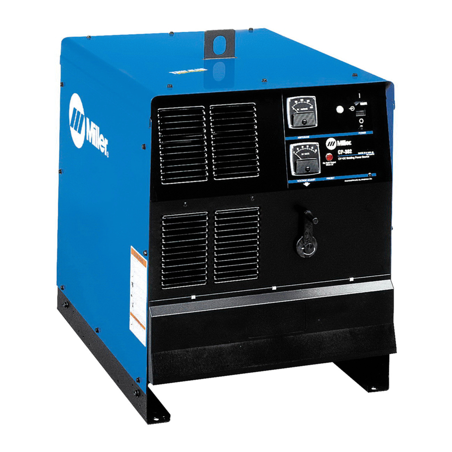
SECTION 3 − OPERATION 3-1. Controls SECTION 4 − MAINTENANCE & TROUBLESHOOTING 4-1. Routine Maintenance Replace Damaged Or Unreadable Labels OM-259 Page 20 Y Disconnect power before maintaining. 3 Months Repair Or Replace Cracked Cables And Cords 6 Months Blow Out Or Vacuum Inside Power Switch Pilot Light... -
Page 25: Overload Protection
4-2. Overload Protection 3/8 in 1/2 in Y Disconnect and lockout/tagout input power before removing side panel. Lockout/tagging procedures consist of padlocking line disconnect switch in open position, removing fuses from fuse box, or shutting off and red-tagging cir- cuit breaker or other disconnecting de- vice. -
Page 26: Troubleshooting
4-3. Troubleshooting Trouble Completely inoperative; fan does not run. No weld output; fan motor FM running. Excessive line current; line fuse(s) and/or circuit breaker(s) open repeatedly. Weld output available; fan does not run. Fan runs slowly. Limited output and low open-circuit voltage. Erratic or improper weld output. -
Page 27: Section 5 − Electrical Diagrams
SECTION 5 − ELECTRICAL DIAGRAMS 212 993-A Figure 5-1. Circuit Diagram For 250 Ampere Model OM-259 Page 23... - Page 28 212 994-A Figure 5-2. Circuit Diagram For 300 Ampere Models OM-259 Page 24...
- Page 29 Notes OM-259 Page 25...
-
Page 30: Section 6 − Parts List
SECTION 6 − PARTS LIST Figure 6-1. Complete Assembly 801 383-J OM-259 Page 26... - Page 31 Item Dia. Part Mkgs....134 464 ....179 430 .
- Page 32 Item Dia. Part Mkgs....036 585 ....180 666 .
- Page 33 Item Dia. Part Mkgs. Figure 6-2. Panel, Front w/Components (continued) (Figure 6-1 Item 30) ... 186 162 ....114 050 .
- Page 34 Item Dia. Part Mkgs....210 324 ....087 461 .
- Page 35 Warranty Questions? Call LIMITED WARRANTY − Subject to the terms and conditions below, Miller Electric Mfg. Co., Appleton, Wisconsin, warrants 1-800-4-A-MILLER to its original retail purchaser that new Miller equipment sold for your local after the effective date of this limited warranty is free of defects in material and workmanship at the time it is shipped by Miller.
- Page 36 File a claim for loss or damage during shipment. For assistance in filing or settling claims, contact your distributor and/or equipment manufacturer’s Transportation Department. 2003 Miller Electric Mfg. Co. 1/03 Miller Electric Mfg. Co. An Illinois Tool Works Company 1635 West Spencer Street Appleton, WI 54914 USA International Headquarters−USA...