ATEN KE6900 User Manual
Dvi kvm over ip extender / matrix manager
Hide thumbs
Also See for KE6900:
- User manual (250 pages) ,
- User manual (366 pages) ,
- User manual (117 pages)
Table of Contents
Advertisement
Quick Links
Download this manual
See also:
User Manual
Advertisement
Table of Contents

Related Manuals for ATEN KE6900


Summary of Contents for ATEN KE6900
- Page 1 DVI KVM Over IP Extender KE6900 / KE6940 / Matrix Manager User Manual www.aten.com...
-
Page 2: Emc Information
KE6900 / KE6940 User Manual EMC Information FEDERAL COMMUNICATIONS COMMISSION INTERFERENCE STATEMENT: This equipment has been tested and found to comply with the limits for a Class A digital device, pursuant to Part 15 of the FCC Rules. These limits are designed to provide reasonable protection against harmful interference when the equipment is operated in a commercial environment. - Page 3 KE6900 / KE6940 User Manual RoHS This product is RoHS compliant. SJ/T 11364-2006 The following contains information that relates to China.
-
Page 4: User Information
KE6900 / KE6940 User Manual User Information Online Registration Be sure to register your product at our online support center: International http://eservice.aten.com Telephone Support For telephone support, call this number: International 886-2-8692-6959 China 86-10-5255-0110 Japan 81-3-5615-5811 Korea 82-2-467-6789 North America... -
Page 5: Package Contents
Copyright © 2015 ATEN® International Co., Ltd. Manual Date: 2015-11-06 Altusen and the Altusen logo are registered trademarks of ATEN International Co., Ltd. All rights reserved. All other brand names and trademarks are the registered property of their respective owners. -
Page 6: Table Of Contents
KE6900 / KE6940 User Manual Contents EMC Information..........ii SJ/T 11364-2006 . - Page 7 KE6900 I/O Ports ........
- Page 8 KE6900 / KE6940 User Manual Online User Stations ........60 Online Transmitters.
- Page 9 KE6900 / KE6940 User Manual Device ........... 111 Assigning Device Permissions From the User’s Notebook .
- Page 10 KE6900 / KE6940 User Manual Verification ..........149 Switch Port Command .
-
Page 11: About This Manual
KE6900 / KE6940 User Manual About This Manual This User Manual is provided to help you get the most from your KE6900 / KE6940 system. It covers all aspects of installation, configuration and operation. An overview of the information found in the manual is provided below. - Page 12 KE6900 / KE6940 User Manual Chapter 12, Firmware Upgrade Utility, explains how to download and use the Firmware Upgrade Utility to install new firmware on the devices. Chapter 13, RS-232 Commands, provides a complete list of the serial control protocol commands used when utilizing the RS-232 Serial Port so that an extra source device can be utilized in the installation.
-
Page 13: Conventions
KE6900 / KE6940 User Manual Conventions This manual uses the following conventions: Monospaced Indicates text that you should key in. Indicates keys you should press. For example, [Enter] means to press the Enter key. If keys need to be chorded, they appear together in the same bracket with a plus sign between them: [Ctrl+Alt]. - Page 14 KE6900 / KE6940 User Manual This Page Intentionally Left Blank...
-
Page 15: Chapter 1 Introduction
(Extender mode), one-to-many (Splitter mode), many-to-one (Switch mode), or many-to-many (Matrix mode). The KE6900 / KE6940 has a local On Screen Display (OSD) on the receiver to configure both units - for easy setup and operation. Using the transmitter and... -
Page 16: Features
Note: 1. RS-232 serial ports support Tx/Rx/CTS/RTS/DTR/DSR signals only. 2. The Matrix Manager web GUI can be updated from the CCKM page on the ATEN website (www.aten.com). 3. The Matrix Manager Lite web GUI can be downloaded by registering your product on the ATEN eService website (http:// eservice.aten.com). -
Page 17: Requirements
Chapter 1. Introduction Requirements Console (KE6900) One DVI compatible monitors capable of the highest possible resolution (KE6940) Two DVI compatible monitors capable of the highest possible resolution A USB mouse A USB keyboard Microphone and speakers Computers The following equipment must be installed on each computer that is to be... -
Page 18: Operating Systems
KE6900 / KE6940 User Manual Operating Systems Supported operating systems are shown in the table, below: Version Windows 2000 and higher Linux RedHat 6.0 and higher SuSE 8.2 and higher Mandriva (Mandrake) 9.0 and higher UNIX 4.3 and higher FreeBSD 3.51 and higher... -
Page 19: Components
Chapter 1. Introduction Components KE6900T (Transmitter) Front View Component Description KVM Ports The USB KVM cable supplied with the package that links the Transmitter to the computer plugs into these ports. RS-232 Port This RS-232 serial port is for connecting to the computer for serial control. -
Page 20: Ke6900T (Transmitter) Rear View
KE6900 / KE6940 User Manual KE6900T (Transmitter) Rear View Component Description Power Jack The cable from the DC Power adapter connects here. Function Switch Use this slide switch to set the unit’s mode to: Configure: The device is ready to configure. -
Page 21: Ke6900R (Receiver) Front View
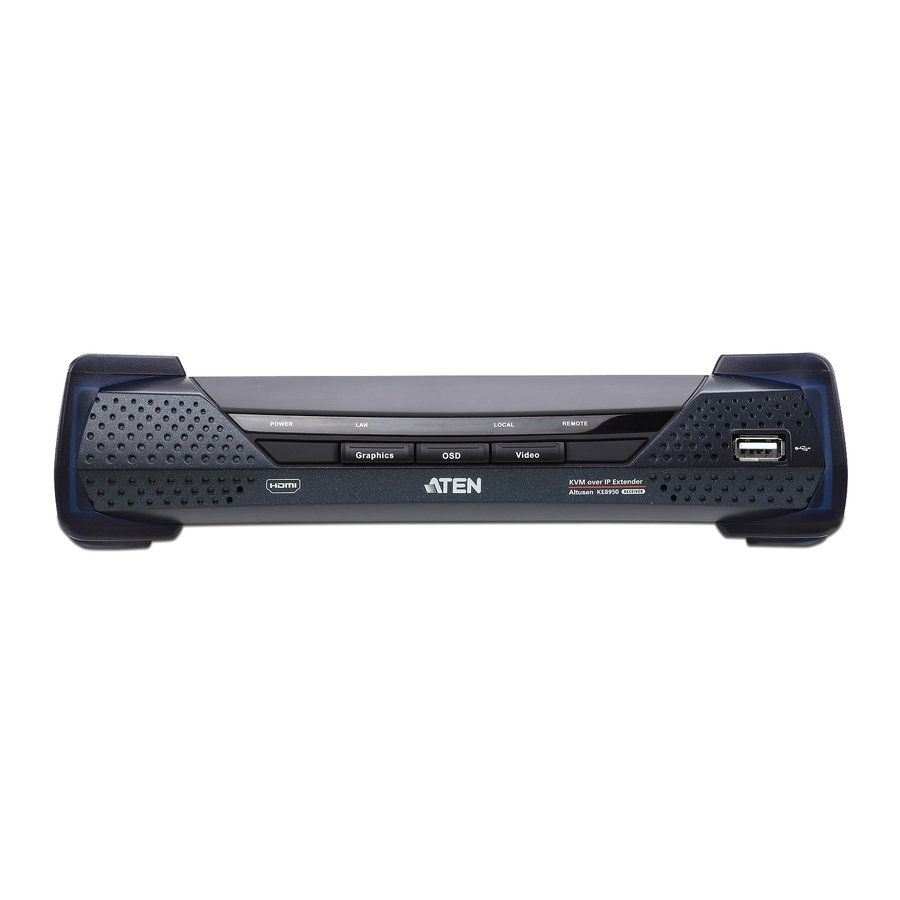
Chapter 1. Introduction KE6900R (Receiver) Front View POWER REMOTE LOCAL Graphics Video Component Description Power LED Lights blue to indicate the module is turned on. LAN LED Lights to indicate the network status: Lights Green when connected to the LAN. Off when not connected to the LAN. -
Page 22: Ke6900R (Receiver) Rear View
KE6900 / KE6940 User Manual KE6900R (Receiver) Rear View Component Description Power Jack The cable from the DC Power adapter connects here. Function Switch Use this slide switch to set the unit’s mode: Extension: Sets the device to use the normal TX to RX extension mode. -
Page 23: Ke6940T (Transmitter) Front View
Chapter 1. Introduction KE6940T (Transmitter) Front View Component Description KVM Ports The USB KVM cable supplied with the package that links the Transmitter to the computer plugs into these ports. RS-232 Port This RS-232 serial port is for connecting to the computer for serial control. -
Page 24: Ke6940T (Transmitter) Rear View
KE6900 / KE6940 User Manual KE6940T (Transmitter) Rear View Component Description Power Jack The cable from the DC Power adapter connects here. Function Switch Use this slide switch to set the unit’s mode to: Configure: The device is ready to configure. -
Page 25: Ke6940R (Receiver) Front View
Chapter 1. Introduction KE6940R (Receiver) Front View POWER REMOTE LOCAL Graphics Video Component Description Power LED Lights blue to indicate the module is turned on. LAN LED Lights to indicate the network status: Lights Green when connected to the LAN. Off when not connected to the LAN. -
Page 26: Ke6940R (Receiver) Rear View
KE6900 / KE6940 User Manual KE6940R (Receiver) Rear View Component Description Power Jack The cable from the DC Power adapter connects here. Function Switch Use this slide switch to set the unit’s mode: Extension: Sets the device to use the normal TX to RX extension mode. -
Page 27: Chapter 2. Hardware Setup
Chapter 2 Hardware Setup 1. Important safety information regarding the placement of this device is found on page 177. Please review it before proceeding. 2. Make sure that the power to all devices connected to the installation is turned off. You must unplug the power cords of any computers that have the Keyboard Power On function. - Page 28 KE6900 / KE6940 User Manual 2. Screw the bracket into a convenient location on the rack. Note: These screws are not provided. We recommend that you use M5 x 12 Phillips Type I cross recessed type screws.
-
Page 29: Wall Mounting
Chapter 2. Hardware Setup Wall Mounting For convenience the Transmitter can be mounted to a wall. 1. Using the screws provided in the Mounting Kit, screw the mounting bracket into the bottom of the Transmitter as show below: Phillips hex head M3 x 8 2. -
Page 30: Setting Up A Point-To-Point Installation
KE6900 / KE6940 User Manual Setting Up a Point-to-Point Installation Setting up the KE6900 / KE6940 system in a point-to-point configuration is simply a matter of plugging in the cables. Note: In a point-to-point configuration, no administrator setup is necessary. -
Page 31: Point-To-Point Installation 1 Of 2
Chapter 2. Hardware Setup Point-to-Point Installation 1 of 2 Cat 5e cable KE6900T Cat 5e cable KE6900R Note: The diagram above shows the KE6900T and KE6900R. The KE6940 installation is the same except that an additional DVI monitor can be connected at each end for a dual-view display setup. -
Page 32: Point-To-Point Installation 2 Of 2
KE6900 / KE6940 User Manual Point-to-Point Installation 2 of 2 KE6900T Local PC USB KVM cable Note: The serial port on the Transmitter (shown above) connects to the computer; the serial port on the Receiver (not shown) connects to a... -
Page 33: Setting Up A Lan Installation
KE6900 / KE6940 devices on the same TCP/IP LAN. Note: 1. The units are preconfigured with factory-default network settings. If you install only one set of KE6900 / KE6940 units, you do not need to change these default network settings. See Default IP Addresses, page 24, for further details. - Page 34 KE6900 / KE6940 User Manual 5. Use a Cat 5e cable to connect the KE6900T / KE6940T’s LAN port to the local area TCP/IP network. 6. Plug the power adapter into an AC source; and plug the other end into the KE6900T / KE6940T’s Power Jack.
-
Page 35: Network Installation Diagram 1 Of 2
Chapter 2. Hardware Setup Network Installation Diagram 1 of 2 Cat 5e cable KE6900T TCP/IP Cat 5e cable KE6900R Note: The diagram above shows the KE6900T and KE6900R. The KE6940 installation is the same except that an additional DVI monitor can be connected at each end for a dual-view display setup. -
Page 36: Network Installation Diagram 2 Of 2
KE6900 / KE6940 User Manual Network Installation Diagram 2 of 2 KE6900T Local PC USB KVM cable Note: The serial port on the Transmitter (shown above) connects to the computer; the serial port on the Receiver (not shown) connects to a... -
Page 37: Network Configuration
IP address, see IP Installer, page 183. Note: 1. Both devices are preconfigured with factory-default network settings. If you install only one set of KE6900 / KE6940 units, you do not need to change these default network settings. See Default IP Addresses, page 24, for further details. -
Page 38: Exit Osd
KE6900 / KE6940 User Manual Note: See Default IP Addresses, page 24, for the preconfigured factory-default settings. Subnet Mask – sets the subnet mask for the KE6900 / KE6940. Key in a valid subnet mask value. Note: The default setting is 255.255.255.0 Default Gateway–... -
Page 39: Ke6900 I/O Ports
Chapter 2. Hardware Setup KE6900 I/O Ports The following table provides the I/O port use of KE6900 devices. Device Port Number KE Manager (TCP) HTTP 8080 HTTPS 8443 Device TCP 9110 9111 Redundancy 9120 Database Service 1527 KE Manager (UDP) - Page 40 KE6900 / KE6940 User Manual This Page Intentionally Left Blank...
-
Page 41: Chapter 3. Osd Operation
Chapter 3 OSD Operation Overview This chapter provides instructions to configure and operate the KE6900 / KE6940 using the local On Screen Display (OSD). To configure the network settings with the OSD, see Network Configuration, page 23. LED Display Both the Transmitter and Receiver have front panel LEDs to indicate their... -
Page 42: Invoking The Osd
KE6900 / KE6940 User Manual Invoking the OSD The On Screen Display (OSD) is a keyboard/mouse-driven application on the receiver used to configure the transmitter and receiver settings. Once the receiver has discovered the transmitter over a network* or direct Ethernet cable connection, you can use the OSD on the receiver to configure the transmitter’s... -
Page 43: Osd Interface
Chapter 3. OSD Operation OSD Interface After you invoke the OSD, the main page appears: Note: A password is required to enter the OSD. The default password is: password. For security purposes, we recommend you change this to something unique. The OSD components are described in the table, below: Item Description... -
Page 44: User Station Configuration
KE6900 / KE6940 User Manual User Station Configuration When you select the User Station radio button and click Configure to login, the Network tab appears: Network The Network tab allows you to configure the User Station’s IP address settings: Item... -
Page 45: Properties
Chapter 3. OSD Operation Properties The Properties tab allows you to configure the User Station’s extender settings: Item Description Mode Select Extender mode for simple one-to-one (Transmitter to User Station) setups that are managed with the Receiver’s OSD menu. Select Desktop/Matrix mode to manage devices and connections from the Matrix Manager web GUI. - Page 46 KE6900 / KE6940 User Manual Item Description RS232 Settings Configure the serial device settings for the User Station. The default settings are: Baud Rate: 9600 Parity: None Data Bits: 8 bits Stop bits: 1 bit Flow Control: None Enable Media Select which type of media the User Station can stream from Transmitters: Video, Audio, USB, and RS232.
-
Page 47: System
Chapter 3. OSD Operation System The System tab allows you to configure the User Station’s general settings: Item Description Device Enter the Name, Location, and Description of the User Information Station. It also displays the IP Address, MAC Address, F/W Version, Serial Number, and Model Number of the User Station. -
Page 48: Transmitter Configuration
KE6900 / KE6940 User Manual Transmitter Configuration When you select the Transmitter radio button and click Configure to login, the Network tab appears: Network The Network tab allows you to configure the Transmitter’s IP address settings: Item Description IP Installer The IP Installer is an external Windows-based utility for assigning an IP address to the device. -
Page 49: Properties
Chapter 3. OSD Operation Properties The Properties tab allows you to configure the Transmitter’s extender settings: Item Description Mode Select Extender mode for simple one-to-one (Transmitter to User Station) setups that are managed with the Receiver’s OSD menu. Select Desktop/Matrix mode to manage devices and connections from the Matrix Manager web GUI. - Page 50 Select how you want the source device to acquire the display's EDID: Default: EDID is set to the default ATEN configuration. Auto: Checks the EDID of all connected displays and uses the best resolution for all displays.
- Page 51 Chapter 3. OSD Operation Item Description Transmitter To set the Transmitter’s video settings: Video Attributes Video Type: Select the DVI video connector being used by the display: Digital (DVI-D) or Digital (DVI-I). Color Depth: Select the number of bits to use for the color depth: 24, 16, or 8.
-
Page 52: System
KE6900 / KE6940 User Manual System The System tab allows you to configure the Transmitter’s general settings: Item Description Device Enter the Name, Location, and Description of the Transmitter. Information It also displays the IP Address, MAC Address, F/W Version, Serial Number, and Model Number of the Transmitter. -
Page 53: User Preferences
Chapter 3. OSD Operation User Preferences When you select the User Preferences radio button and click Configure to login, the configuration screen appears: Item Description User Password This section allows you to change the OSD password: Change 1. Key in the old password in the Old password field. 2. -
Page 54: Connecting
KE6900 / KE6940 User Manual Connecting If the User Station is set to Extender mode, the video screen of the remote computer will appear automatically when you exit the OSD (tap the Scroll Lock key twice). In Desktop/Matrix mode you will see the System Login... -
Page 55: Connections Page
Chapter 3. OSD Operation Connections Page After you have successfully logged in the Connection Page appears: List Mode The Connection Page components are described in the table, below: Item Description Channel Name Lists the Channel connections available for the User Station. - Page 56 KE6900 / KE6940 User Manual Item Description Connect To connect the User Station to a Channel, click the access type: Exclusive: The first User Station to access the Channel has exclusive control over the Channel. No other User Stations can view the Channel. The Timeout function does not apply to this setting.
-
Page 57: Array Mode
Chapter 3. OSD Operation Array Mode... -
Page 58: Profile / Video Wall Page
KE6900 / KE6940 User Manual Profile / Video Wall Page Click the Profile / Video Wall Page tab and the following screen appears: The Profile /Video Wall Page components are described in the table, below: Item Description Name Lists the Profiles and Video Walls available. Profiles / Video Walls give User Stations access to Channels and allow you to push the connection. - Page 59 Chapter 3. OSD Operation Item Description Video Wall Click to view a list of available Video Wall connections. Appears when the Profile button has been clicked. Profile Click to view a list of available Profile connections. Appears when the Video Wall button has been clicked.
- Page 60 KE6900 / KE6940 User Manual This Page Intentionally Left Blank...
-
Page 61: Matrix Manager Installation
The Matrix Manager is a browser based GUI that provides management of KE6900 / KE6940 devices over a network. Download and install the software to begin managing the KE6900 / KE6940 devices from a computer using a web browser. Download To download the Matrix Manager Lite software, do the following: →... - Page 62 Note: The trial software includes full functions to setup and configure single device installations. The trial version will not expire. If you would like to purchase the advanced software, please contact your ATEN reseller. 5. Click the software version you would like to download, then click Save.
-
Page 63: Matrix Manager Install
Chapter 4. Matrix Manager Installation Matrix Manager Install The following are instructions to install the full version of the Matrix Manager software. For software requirements, see Software, page 3. 1. Insert the USB license key into a USB port on your computer. 2. - Page 64 KE6900 / KE6940 User Manual If you agree with the License Agreement, select I accept the terms of the license agreement, and click Next. 4. The Choose Install Folder screen appears: Select where you would like to install the program, and click Next.
- Page 65 Chapter 4. Matrix Manager Installation 6. The Pre-Installation Summary screen appears: Confirm the settings you’ve selected. If you want to make a change click Previous to go back, or click Install to begin the software installation. 7. When the process is done, the Install Complete screen appears: Click Done.
- Page 66 KE6900 / KE6940 User Manual This Page Intentionally Left Blank...
-
Page 67: Chapter 5. Browser Operation
Chapter 5 Browser Operation Overview The Matrix Manager software can be accessed through most standard web browsers. Once users log in and are authenticated, the browser GUI comes up. This chapter explains the login procedure and web browser components. Logging In To log into the Matrix Manager, do the following: 1. -
Page 68: The Matrix Manager Main Page
KE6900 / KE6940 User Manual The Matrix Manager Main Page After you have successfully logged in, the web browser’s main page appears: Web Components The web components are described in the table, below: Item Description Tab Bar The tab bar contains the Matrix Manager’s main... -
Page 69: Tree View Considerations
Chapter 5. Browser Operation Tree View Considerations On some pages there will be a sidebar menu with options that can be expanded: A plus (+) sign in front of an item means that there are additional items nested inside of it. Click the plus sign to expand the view and show the nested items. -
Page 70: The Tab Bar
KE6900 / KE6940 User Manual The Tab Bar The functions associated with each of the tabs are explained in the table below: Icon Function Dashboard: The Dashboard is used to view information about current connections, sessions, and device events. The first page provides an overview and the sidebar provides a link to view details about each section. -
Page 71: Chapter 6 Dashboard
Chapter 6 Dashboard Overview The Dashboard tab is used to view events about connections, sessions, online devices and schedules. The Home page provides an overview of the information provided in each section. The Sidebar provides a link to each section in the Dashboard. The Dashboard opens on the Home page, as shown here: At the bottom of the page, click Shutdown* to stop the KeManager service, or Restart to stop and restart the service. -
Page 72: Active Connections
KE6900 / KE6940 User Manual Active Connections The Active Connections page lets an administrator see the active Channel connections (User Stations connected to Transmitters) and provides information about each of their sessions. The meanings of the headings at the top of the page are straightforward. -
Page 73: Active Sessions
Chapter 6. Dashboard Active Sessions The Active Sessions page shows all of the users that are logged into Matrix Manager and OSD sessions and provides information concerning the “who, where and when” of each session. This page also gives the administrator the option of forcing a user logout by selecting the user and clicking Kill Session from the bottom of the page. -
Page 74: Online User Stations
KE6900 / KE6940 User Manual Online User Stations The Online User Stations page lets the administrator see all of the Receivers that are currently available on the network and provides information about each device. The meanings of the headings at the top of the page are straightforward. -
Page 75: Online Transmitters
Chapter 6. Dashboard Online Transmitters The Online Transmitters page lets the administrator see all of the Transmitters that are currently available on the network and provides information about each device. The meanings of the headings at the top of the page are straightforward. ID refers to the identification number assigned by the system. -
Page 76: Latest Events
KE6900 / KE6940 User Manual Latest Events The Latest Events page lets the administrator see the most recent Dashboard events that relate to the current connections and sessions, and provides details about each. The meanings of the headings at the top of the page are straightforward. -
Page 77: Schedule
Chapter 6. Dashboard Schedule The Schedule page lets the administrator see all of the Profiles and Video Walls that are scheduled to activate. The meanings of the headings at the top of the page are straightforward. Profiles/Video Walls refers to the ID number created for the Profile or Video Wall schedule. - Page 78 KE6900 / KE6940 User Manual This Page Intentionally Left Blank...
-
Page 79: Chapter 7. Device Management
Chapter 7 Device Management Overview The Device Management tab contains five menu bar items: User Stations, Transmitters, Channels, Profiles and Video Walls. Each page provides a way to add, configure and schedule the Transmitters/Receivers connections. Before Transmitters and Receivers can be added they must be connected to the network and have an IP address. -
Page 80: User Stations
KE6900 / KE6940 User Manual User Stations The User Stations page allows you to add and configure Receivers. The Sidebar provides three menu options: User Stations, Unmanaged User Stations and User Station Video Group. User Stations are the Receivers that have been added to the Matrix Manager. -
Page 81: Adding A User Station
Chapter 7. Device Management Adding a User Station To add a User Station, do the following: 1. From Unmanaged User Stations, select a User Station and click Add in: or click Search New: You can search for a device by Local, Subnet, or IP address. Select a scope, enter the information and click Search. -
Page 82: Configuring A User Station
KE6900 / KE6940 User Manual Configuring a User Station A User Station’s settings can be modified from the User Stations main page. Changes that are saved here are then updated on the Receiver across the network. To configure a User Station: 1. - Page 83 Chapter 7. Device Management Item Description Network For dynamic IP address assignment, select the Obtain IP Configuration address automatically radio button. To specify a fixed IP Address, Subnet Mask, and Default Gateway select the Set IP address manually radio button and fill in the fields with values appropriate for your network.
- Page 84 KE6900 / KE6940 User Manual Item Description RS-232 Settings Configure the settings for the serial device the User Station will be connecting to. The default settings are: Baud Rate: 9600 Parity: None Data Bits: 8 bits Stop bits: 1 bit...
- Page 85 Chapter 7. Device Management 4. Click the System tab to configure the general settings: Item Description General Enter the Name, Location, and Description of the User Station. This section also displays the User Station’s IP Address, F/W Version, Model Name, MAC Address and MFG*. Note: The MFG number (manufacturing number) is an internal serial number for our factory and technical support staff to identify products.
-
Page 86: Deleting A User Station
KE6900 / KE6940 User Manual Deleting a User Station To delete a User Station: 1. Select the User Station you want to delete. 2. Click Move Out. The device list updates with the remaining User Stations. The User Station you deleted will appear on the Unmanaged User Stations main page and Sidebar menu. -
Page 87: User Station Video Group
Chapter 7. Device Management User Station Video Group Creating a User Station Video Group allows you to cascade up to four Transmitters connected to separate video cards on one computer and share the video with four User Stations – while giving the first User Station keyboard and mouse access. -
Page 88: Adding A User Station Video Group
KE6900 / KE6940 User Manual 3. Setup the Receivers as you normally would. All Receivers can have a keyboard and mouse but only one (Video 1) can work on the computer for the group. 4. Note the Receiver and Transmitter with keyboard and mouse access (to the computer) so they can be set in the User Station Video Group (as Video 1) and in the Channel (as KVM Transmitter). - Page 89 Chapter 7. Device Management Note: All Receivers can switch KVM access to other Transmitters but only Video 1 has keyboard and mouse access to the computer for the group. 5. Use the Video 2, Video 3 and Video 4 drop-down menus to select the other Receivers for the group.
-
Page 90: Transmitters
KE6900 / KE6940 User Manual Transmitters The Transmitters page allows you to add, configure, and delete Transmitters. The Sidebar provides two options: Transmitters and Unmanaged Transmitters. Unmanaged Transmitters are Transmitters on the network that haven’t been added to the Matrix Manager. For the Matrix Manager to discover a Transmitter, it must be connected to the local network with an IP address. -
Page 91: Adding A Transmitter
Chapter 7. Device Management Adding a Transmitter To add a Transmitter, do the following: 1. From Unmanaged Transmitters, select a Transmitter and click Add in: or click Search New: You can search for a device by Local, Subnet, or IP address. Select a scope, enter the information and click Search. -
Page 92: Configuring A Transmitter
KE6900 / KE6940 User Manual Configuring a Transmitter A Transmitter’s settings can be modified from the Transmitters main page. Changes that are saved are updated on the Transmitter device across the network. To configure a Transmitter: 1. Select a Transmitter and click Modify. - Page 93 Chapter 7. Device Management Item Description Network For dynamic IP address assignment, select the Obtain IP Configuration address automatically radio button. To specify a fixed IP Address, Subnet Mask, and Default Gateway, select the Set IP address manually radio button and fill in the fields with values appropriate for your network.
- Page 94 Select how you want the source device to acquire the display's EDID: Default: EDID is set to the default ATEN configuration. Auto: Checks the EDID of all connected displays and uses the best resolution for all displays.
- Page 95 Chapter 7. Device Management Item Description Transmitter These refer to the Transmitter’s video settings: Video Setting Video Type: Select the DVI video connector being used by the display: Digital (DVI-D) or Digital (DVI-I). Color Depth: Select the number of bits to use for the color depth: 24, 16, or 8.
-
Page 96: Deleting A Transmitter
KE6900 / KE6940 User Manual Item Description General Enter the Name, Location, and Description of the Transmitter. This section also displays the IP Address, MAC Address, F/W Version, Serial Number, and Model Number. Reboot Check the box and click Reboot to reset the Transmitter’s settings back to the factory default. -
Page 97: Channel Connections
Chapter 7. Device Management Channel Connections With Channel connections a User Station can connect to multiple Transmitters, individually or simultaneously and stream the Video, Audio, USB, and Serial source from different Transmitters. For example: you can create a Channel that connects to four Transmitters to access a different source on each computer, as shown below: Transmitters... -
Page 98: Channels
KE6900 / KE6940 User Manual Channels A Channel defines the Transmitter connections for a User Station. This allows a User Station to connect to different Transmitters and stream sources from different Transmitters, depending on how the Channel is defined. Once Channels are created you can select them from the User Station’s Connection... -
Page 99: Adding A Channel
Chapter 7. Device Management Adding a Channel To add a Channel, do the following: 1. From the Channels main page, click Add: 2. The Channel Info tab appears with the general settings: Item Description General Enter a Name, Location, and Description for the Channel. Source Stream Use the drop-down menu to select the Transmitter to use for each of the Channel’s source stream: KVM (keyboard/video/... - Page 100 KE6900 / KE6940 User Manual Item Description Allowed Access Check the box for the type of access mode you want to allow on Mode this Channel. This defines how the Channel can be accessed when multiple users access it. View Only: Users only have view access to the Channel’s video display.
- Page 101 Chapter 7. Device Management 4. Click the Permissions tab to set the Channels access rights: Item Description Users/Groups You can assign individual access rights to Users and Groups for the Channel by checking the appropriate boxes: View Only: Only has view access to the Channel’s video display.
-
Page 102: Channel Groups
KE6900 / KE6940 User Manual Channel Groups Channel Groups allow administrators to easily and efficiently manage users and Channels. Since Channel Group access rights apply to any Channel that is a member of the group, administrators need only set them once for the group, instead of having to set them for each Channel individually. - Page 103 Chapter 7. Device Management 3. Click the Members tab to add Channels to the group: Select a Channel from the Selected column and use the left arrow to add it to the group. Select a Channel from the Available column and use the right arrow to remove it from the group.
-
Page 104: Profiles
KE6900 / KE6940 User Manual Profiles Profiles are created for Channels to allow User Station access to the connection. Create a Profile for a Channel and assign access for each User Station. Click Profiles from the menu bar and the following screen appears: The main page provides an overview of each Profile. -
Page 105: Adding A Profile
Chapter 7. Device Management Adding a Profile To add a Profile, do the following: 1. From the Profile main page, click Add: 2. The Profile Settings tab appears with the Profile and access settings: Item Description Name/ Enter a Name and Description for the Channel. Description... - Page 106 KE6900 / KE6940 User Manual Item Description Access This defines how the Channel in the Profile can be accessed by Mode User Stations when multiple users access it. View Only: Users only have view access to the Channels video display.
- Page 107 Chapter 7. Device Management Item Description Routine Use the drop-down menu to select how often you would like the Type profile to run: Once, Daily, Weekly and Monthly. If you select Weekly/ Monthly an additional drop-down menu appears to select the Week Day/Month Day on which the profile will run.
-
Page 108: Video Wall
KE6900 / KE6940 User Manual Video Wall The Video Wall settings allow you to create a video wall by selecting a Transmitter for a set of User Stations that will display video content as one screen. A video wall is considered a single connection from a Transmitter to multiple User Stations. -
Page 109: Video Wall Example
Chapter 7. Device Management Video Wall Example The diagram below shows a 3x3 video wall setup with three Transmitters (video sources) connected to nine User Stations. In this scenario, three Video Wall settings (A, B, C) need to be added to the Matrix Manger. Transmitters User Stations Video TX... -
Page 110: Adding A Video Wall
KE6900 / KE6940 User Manual Adding a Video Wall To add a Video Wall, do the following: 1. From the Video Wall main page, click Add: 2. The Video Wall Settings tab appears allowing you to configure the settings: Item... - Page 111 Chapter 7. Device Management Item Description Access This defines how the Source Channel (Transmitter) can be Mode accessed by User Stations when multiple users attempt to access it. View Only: Users only have view access to the Source Channel video output. Share: Users simultaneously share control over the Source Channel.
- Page 112 KE6900 / KE6940 User Manual 3. Click the Schedule tab if you want to schedule a time for the video wall to connect. A pop-up window appears: Item Description Routine Use the drop-down menu to select how often you would like the video Type wall to run: Once, Daily, Weekly and Monthly.
- Page 113 Chapter 7. Device Management Item Description Users You must assign access rights for the Video Wall by selecting the Operation check box for the Users that you want to grant permission to allow the connections. Groups You must assign access rights for the Video Wall by selecting the Operation check box for the Groups that you want to grant permission to allow the connections.
- Page 114 KE6900 / KE6940 User Manual This Page Intentionally Left Blank...
-
Page 115: Chapter 8. User Management
Chapter 8 User Management Overview User Management has two menu bar items used to create Accounts and Groups. The User Management tab opens on the Accounts page, as shown here: The page is organized into two main areas: the Sidebar at the left, and the large main panel at the right. -
Page 116: Users
KE6900 / KE6940 User Manual Users The Matrix Manager supports three types of user accounts, shown in the table bellow: User Type Role Administrator Access and management of the Matrix Manager, including configuration and setting up of devices. Manage Users, Groups, Channels, Profiles and Video Walls. - Page 117 Chapter 8. User Management Field Description Local User Check the Local User box if the account is for logging in to the Matrix Manager or a User Station (Receiver). Uncheck the Local User box if the account is authenticated with a 3rd party external source, such as RADIUS, LDAP/ AD, or TACACS+.
-
Page 118: Modifying User Accounts
KE6900 / KE6940 User Manual The Sidebar Users list can expand and collapse. If the list is expanded, click the minus symbol ( – ) next to the Users icon to collapse it; if it is collapsed there is a plus symbol ( + ) next to the icon. Click the plus symbol to expand it. -
Page 119: Groups
Chapter 8. User Management Groups Groups allow administrators to easily and efficiently manage users and devices. Since device access rights apply to anyone who is a member of the group, administrators need only set them once for the group, instead of having to set them for each user individually. -
Page 120: Modifying Groups
KE6900 / KE6940 User Manual The Sidebar Group list can expand and collapse. If the list is expanded, click the minus symbol ( – ) next to the Users icon to collapse it; if it is collapsed there is a plus symbol ( + ) next to the icon. Click the plus symbol to expand it. -
Page 121: Users And Groups
Chapter 8. User Management Users and Groups There are two ways to manage users and groups: from the Users notebook; and from the Group notebook. Note: Before you can assign users to groups, you must first create them. See Adding Users, page 102 for details. Assigning Users to a Group From the User’s Notebook To assign a user to a group from the User’s notebook, do the following: 1. -
Page 122: Removing Users From A Group From The User's Notebook
KE6900 / KE6940 User Manual Removing Users From a Group From the User’s Notebook To remove a user from a group from the User’s notebook, do the following: 1. In the Sidebar User list, click the user’s name – or –... -
Page 123: Assigning Users To A Group From The Group's Notebook
Chapter 8. User Management Assigning Users to a Group From the Group’s Notebook To assign a user to a group from the Group notebook, do the following: 1. In the Sidebar Group list, click the group’s name – or – In the main panel, select the group’s name. -
Page 124: Removing Users From A Group From The Group's Notebook
KE6900 / KE6940 User Manual Removing Users From a Group From the Group’s Notebook To remove a user from a group from the Group’s notebook, do the following: 1. In the Sidebar Group list, click the group’s name – or –... -
Page 125: Device
Chapter 8. User Management Device You can assign Channel and Channel Group permissions from the Devices tab. For information on Channels and Channel Groups See Channels, page 84. Assigning Device Permissions From the User’s Notebook To assign a device permissions to a user from the User’s notebook, do the following: 1. - Page 126 KE6900 / KE6940 User Manual Field Description Columns Check the boxes to apply access rights on the device for the user. This defines how the Channel can be accessed when multiple users access it. View Only: Users can only view the remote screen, and cannot perform operations on it.
-
Page 127: Assigning Device Permissions From The Groups' Notebook
Chapter 8. User Management Assigning Device Permissions From the Groups’ Notebook To assign a device permissions to a Group of users, do the following: 1. In the Sidebar Groups list, click the group’s name – or – In the main panel, select the group’s name. 2. -
Page 128: Profiles/Video Walls
KE6900 / KE6940 User Manual Profiles/Video Walls You can assign Profile and Video Wall permissions from the Profiles/Video Walls tab. For information on Profiles and Video Walls, see Profiles, page 90 or Video Wall, page 94. Assigning Profile/Video Wall Permissions From the User’s Notebook To assign a Profile/Video Wall permission to a user from the User’s notebook,... - Page 129 Chapter 8. User Management Field Description Operation Put a check in the box to grant permission for the user to connect to Profiles/Video Walls. 5. When you have finished making your choices, click Save.
-
Page 130: Chapter 9 System
Chapter 9 System Overview The System tab is used to configure the Matrix Manager’s system settings and provides three menu bar items: Global Settings, ANMS and Redundancy. The System tab opens on the Global Settings page, as shown here:... -
Page 131: Global Settings
Chapter 9. System Global Settings The Global Settings page lets an administrator change the default settings used for the Matrix Manager: Item Description General Fill in a Name and Description for the Matrix Manager. Network Ports Use this setting to specify the service ports used to access the Matrix Manager: Device Port: This is the port number to configure on the Transmitter and User Station to access the Matrix Man-... - Page 132 KE6900 / KE6940 User Manual Item Description Allowed Access Mode Select the default Access Mode for devices added to the Matrix Manager. This defines how the device can be accessed when multiple users log on. View Only: Users can access the computer and view the screen, but cannot perform any operations on it.
- Page 133 This will be the default setting for Transmitters. Select how you want the source device to acquire the display's EDID: Default: EDID is set to the ATEN default configuration. Auto: Checks the EDID of all connected displays and uses the best resolution for all displays.
-
Page 134: Anms
KE6900 / KE6940 User Manual ANMS The ANMS (Advanced Network Management Settings) page is used to set up login authentication and authorization management from external sources. It is organized as a notebook with two tabs – each with a series of related panels, as described below. - Page 135 Chapter 9. System Note: 1. Only one email address is allowed in the From field, and it cannot exceed 64 Bytes. 2. 1 Byte = 1 English alphanumeric character. 4. Key in the email address (addresses) of where you want the SMTP reports sent to in the To field.
-
Page 136: Authentication & Authorization
KE6900 / KE6940 User Manual Authentication & Authorization RADIUS Settings To allow authentication and authorization for the KE6900 / KE6940 through a RADIUS server, do the following: 1. Check Enable. 2. Fill in the IP addresses and service port of the Preferred RADIUS Server and Alternate RADIUS Server. - Page 137 LDAP / AD server reply before it times out. Admin DN Consult the LDAP / AD administrator to ascertain the appropriate entry for this field. For example, the entry might look like this: ou=kn4132,dc=aten,dc=com Admin Name Key in the LDAP administrator’s username. Password Key in the LDAP administrator’s password.
- Page 138 KE6900 / KE6940 User Manual On the LDAP / AD server, Users can be authenticated with any of the following methods: With MS Active Directory schema. Note: If this method is used, the LDAP schema for MS Active Directory must be extended. Without schema – Only the Usernames used on the Matrix Manager are matched to the names on the LDAP / AD server.
-
Page 139: Redundancy
Chapter 9. System Redundancy The Redundancy page sets up a second computer as backup in case the computer hosting the Matrix Manager goes off-line. If the Matrix Manager is off-line, the secondary computer will automatically take over operations, allowing all connections to continue without disruption – with only a brief period (30 seconds) when new connections can't be started. - Page 140 KE6900 / KE6940 User Manual 5. Use the Master drop-down menu to select the primary computer’s IP address. 6. Click OK. 7. This computer is now running in Standby mode, as identified in the orange status bar: 8. Remove the USB License key and plug it into the primary computer running the Matrix Manager software.
- Page 141 Chapter 9. System 11. Check the Enable Redundancy box and select the Master radio button. 12. Use the Slave drop-down menu to select the secondary computer’s IP address. 13. Enter the Username and Password of the secondary computer’s local administrator account. 14.
- Page 142 KE6900 / KE6940 User Manual Item Action Peer ID Displays the MAC address of the computer configured to send (primary) or receive (secondary) the database updates for redundancy. Auto Switch Displays the Auto Switch (Yes/No) status. (Master only). Event Log Displays the logs that provide information about the Matrix Manager's redundancy status.
-
Page 143: Chapter 10 Logs
Chapter 10 Logs Overview The Matrix Manager logs all the events that take place on it an stores them in a Log. The Logs tab opens on the System Log page, as shown here:... -
Page 144: System Log
KE6900 / KE6940 User Manual System Log The System Log page displays events that take place on the Matrix Manager and provides a breakdown of the time, user, severity, device, and log information, for a description of each event. You can change the sort order of the display by clicking on the column headings. - Page 145 Chapter 10. Logs The log file tracks a maximum of 512 events. When the limit is reached, the oldest events get discarded as new events come in. The buttons at the bottom of the page are shown below and described in the tables below: Button Explanation Navigation Buttons...
-
Page 146: Filter
KE6900 / KE6940 User Manual Filter Filter lets you narrow the log event display to ones that occurred at specific times; ones containing specific words or strings. When you access this function, the log filter dialog box appears at the bottom of the page:... -
Page 147: Chapter 11 Maintenance
Chapter 11 Maintenance Overview The Maintenance tab has four menu bar options: Backup/Restore, Firmware Upgrade, Certificates, and Preferences. When you click the Maintenance tab, it opens on the Backup/Restore page, as shown here: Backup/Restore allows administrators to backup system configuration settings to a file, and restore configuration settings from previously saved files. -
Page 148: Backup / Restore
KE6900 / KE6940 User Manual Backup / Restore When you click the Maintenance tab Matrix Manager, the Backup/Restore page is displayed. The page is divided into two main sections: Backup, and Restore: The operations to perform backup/restore procedures are described in the table... -
Page 149: Backup
Chapter 11. Maintenance Backup To back up system configuration settings, do the following: 1. (Optional) In the Backup panel, provide a password for the backup file. Any combination of characters may be used for the password. Note: Providing a password is a security feature – if you provide a password, you will need to give the same password in order to restore the configuration settings from this file. -
Page 150: Firmware Upgrade
3. Click the Maintenance tab; select Firmware Upgrade on the menu bar. A confirmation dialog box may appear: 4. Click Yes to continue. After a short while, the Firmware Upgrade page comes up: All the KE6900 / KE6940 devices that are capable of being upgraded are listed. -
Page 151: Firmware Upgrade Recovery
Chapter 11. Maintenance Note: Only online KE6900 / KE6940 devices show up in the list. Offline devices do not get upgraded. 5. Make sure there is a check in the checkbox in front of the modules you want to upgrade. Uncheck the modules that you do not want to upgrade. -
Page 152: Certificates
For enhanced security, the Private Certificate section allows you to use your own private encryption key and signed certificate, rather than the default ATEN certificate. There are two methods for establishing your private certificate: generating a self-signed certificate;... -
Page 153: Certificate Signing Request
2. Click Browse to the right of Certificate Filename; and browse to where your certificate file is located; and select it. 3. Click Import to complete the procedure. Note: Clicking Restore Defaults returns the device to using the default ATEN certificate. Certificate Signing Request The Certificate Signing Request (CSR) section provides an automated way of obtaining and installing a CA signed SSL server certificate. - Page 154 KE6900 / KE6940 User Manual Information Example State or Province Taiwan Locality Taipei Organization Your Company, Ltd. Organization Unit Tech Department Common Name mycompany.com Note: This must be the exact domain name of the site that you want the certificate to be valid for. If the site’s domain name is www.mycompany.com, and you only...
-
Page 155: Preferences
Matrix Manager can be accessed again. The default is 30 minutes. Screen Blanker Set how many minutes the KE6900 / KE6940 waits when a session is idle before turning off the display. Welcome Page If you want the Welcome Message to appear on screen when the user logs in, select Enable. - Page 156 KE6900 / KE6940 User Manual Item Description Password This section allows you to change the user’s password: 1. Key in your old password in the Old password field. 2. Key in your new password in the New password field. 3. Key in your new password again in the Confirm password field.
-
Page 157: Chapter 12. Firmware Upgrade Utility
1. From a computer that is not part of your KVM installation go to our Internet support site and choose the model name that relates to your device KE6900 / KE6940 to get a list of available Firmware Upgrade Packages. 2. Choose the Firmware Upgrade Package you want to install (usually the most recent), and download it to your computer. -
Page 158: Starting The Upgrade
KE6900 / KE6940 User Manual Starting the Upgrade To upgrade your firmware: 1. Run the downloaded Firmware Upgrade Package file - either by double clicking the file icon, or by opening a command line and entering the full path to it. The Firmware Upgrade Utility Welcome screen appears: Note: The screens shown in this section are for reference only. - Page 159 Chapter 12. Firmware Upgrade Utility 4. The Utility inspects your installation. All the devices capable of being upgraded by the package are listed in the Select Master Device list. 5. After you have made your device selection, Click OK and then Next to begin the upgrade.
-
Page 160: Upgrade Succeeded
KE6900 / KE6940 User Manual Upgrade Succeeded After the upgrade has completed, a screen appears to inform you that the procedure was successful:... -
Page 161: Firmware Upgrade Recovery
1. Power off the KE6900 / KE6940. 2. Press the Reset button, then power on the KE6900 / KE6940 while holding Reset. 3. Hold Reset for 5 seconds after the device is powered on. - Page 162 KE6900 / KE6940 User Manual This Page Intentionally Left Blank...
-
Page 163: Rs-232 Commands
Chapter 13 RS-232 Commands Serial Control Protocol Commands The KE6900 / KE6940’s built-in bi-directional RS-232 serial interface allows system control via User Stations through a high-end controller or PC. Configuring the Serial Port The controller’s serial port should be configured the same as the User Station’s... -
Page 164: Switch Port Command
KE6900 / KE6940 User Manual Switch Port Command The formula for Switch Port commands is as follows: Command + Output + Num1 + Input + Num2 + Mode + Stream + Connect + [Enter] 1. For example, if you want to switch the User Station’s connection to Transmitter (192.168.0.20), type the following:... - Page 165 Chapter 13. RS-232 Commands The following tables show the possible values for the Switch Port commands: Command Description Switch port command Output Description Output port command (RX) Num1 Description Output port xx: User Station ID or IP address List # zz: 1~99 To use the 4th User Station listed in the command line interface,...
- Page 166 KE6900 / KE6940 User Manual Stream Description Sets the USB source stream Sets all source streams Connect Description Connect Disconnect logout Logout OSD The following table lists the available Switch Port commands: Con- Description Command Output Num1 Input Num2 Mode...
- Page 167 Chapter 13. RS-232 Commands Con- Description Command Output Num1 Input Num2 Mode Stream nect Switch User Station disconnect streams, return to OSD menu. exclusive video Switch User Station to input @zz with [mode] share audio access to stream occupy serial source(s).
-
Page 168: Mute Command
KE6900 / KE6940 User Manual Mute Command The Mute command allows you to enable or disable the audio. The formula for the Mute command is as follows: Command + Output + Num1 + Control + [Enter] 1. For example, to turn mute off (audio on) for the User Station, type the... - Page 169 Chapter 13. RS-232 Commands Command Output Num1 Control Description mute Turn mute on for User Station mute Turn mute off for User Station Note: 1. Each command string can be separated with a space. 2. The Control command string can be skipped and off will be used by default.
-
Page 170: Profile Command
KE6900 / KE6940 User Manual Profile Command The Profile command allows you to connect profiles and video walls. The formula for Profile commands is as follows: Command + Profile + Num1 + Control + [Enter] 1. For example, to connect profile 8 and lock the OSD menu, type the... - Page 171 Chapter 13. RS-232 Commands The following table lists the available Profile commands: Command Profile Num1 Control Description profile lock Connect profile xx, lock OSD access xx:1~99 profile release Connect profile xx, allow OSD access xx:1~99 profile back Disconnect profile xx and return User Station to OSD menu xx: 1~99...
-
Page 172: Edid Command
KE6900 / KE6940 User Manual EDID Command Extended Display Identification Data (EDID) is a data that contains a display's basic information and is used to communicate with the video source. The EDID commands allow you to change the EDID setting of a Transmitter. - Page 173 Chapter 13. RS-232 Commands Command Address Number Control Enter Description edid remix [Enter] Set EDID of address xx to remix. xx: Device ID or IP Address edid default [Enter] Set EDID of address xx to default. xx: Device ID or IP Address edid manual [Enter] Set EDID of address xx to...
-
Page 174: Reset Command
KE6900 / KE6940 User Manual Reset Command The Reset command allows you to reset a device back to the default factory settings. Reset includes resetting the devices IP address. The formula for the Reset command is as follows: Command + Address + Number + [Enter] 1. -
Page 175: Rs-232 Command
Chapter 13. RS-232 Commands RS-232 Command The RS-232 command allows you to set the RS-232 settings for a device. The formula for the RS-232 command is as follows: Command + Address + Number + Baud Rate + Parity + Data Bit + Stop Bit + Flow Control [Enter] 1. - Page 176 KE6900 / KE6940 User Manual Data Bit Description Sets the data bit to 7 Sets the data bit to 8 Stop Bit Description Sets the stop bit to 1 Sets the stop bit to 2 Flow Control Description None Sets flow control to none...
- Page 177 Chapter 13. RS-232 Commands Baud Data Stop Flow Address Parity Description mand Rate Control baud 9600 Set local device baud rate to 9600 baud 19200 Set local device baud rate to 19200 baud 38400 Set local device baud rate to 38400 baud 115200...
-
Page 178: Osd Command
KE6900 / KE6940 User Manual OSD Command To enable or disable the On-Screen Display (OSD) menu for a User Station, use the following command: Command + Output + Number + Control + [Enter] 1. For example, to enable the OSD for User Station 192.168.0.51, type: osd o192.168.0.51 on [Enter]... -
Page 179: List Command
Chapter 13. RS-232 Commands List Command The List command allows you to retrieve information about users, settings and connections. The formula for the List command is as follows: Command + Output + Input + Number + Control [Enter] 1. For example, for a complete list of available channels, type the following: list channel [Enter] 2. - Page 180 KE6900 / KE6940 User Manual Control Description channel Lists information about the available channel(s) profile Lists information about the available profile and TV wall connections Lists information about the User Sta- tion login Lists information about users logged into to the OSD menu...
-
Page 181: Read Command
Chapter 13. RS-232 Commands Read Command The Read command allows you to retrieve the properties of a device. The formula for the Read command is as follows: Command + Output + Input + Number + Control [Enter] 1. For example, to read all of the local User Station’s properties, type the following: read all [Enter] 2. - Page 182 KE6900 / KE6940 User Manual Control Description basic Read basic properties network Read network properties ipsettings Read IP settings rs232 Read RS232 properties properties Read connection properties manager Read Matrix Manager properties streams Read enable media properties Read source stream IP properties...
- Page 183 Chapter 13. RS-232 Commands Comman Output Input Number Control Description read rs232 Read output or input xx RS-232 properties xx: Device ID or IP address read properties Read output or input xx connection properties xx: Device ID or IP address read manager Read output or input xx...
- Page 184 KE6900 / KE6940 User Manual Comman Output Input Number Control Description read basic Read [control] network properties of local User ipsettings Station. rs232 properties manager streams usbmode Note: 1. Each command string can be separated with a space. 2. Skip the Output or Input and Number command strings to read the...
-
Page 185: Set Command
Chapter 13. RS-232 Commands Set Command The Set command allows you to configure the properties of a device. Some settings require that both the device and Matrix Manger are online or the command will fail. For a list of available “values” see the section of the Matrix Manager that the setting relates to. - Page 186 KE6900 / KE6940 User Manual Type Control Description System Name Sets the device name Description Sets the device description Network ipInstallerFlag Sets the IP installer option dhcpFlag Sets the DHCP setting ipAddr Sets the IP address netmask Sets the subnet mask...
- Page 187 Chapter 13. RS-232 Commands Type Control Description Properties modeFlag Sets the device mode (Transmitter) BaudRate Sets the baud rate setting Parity Sets the parity setting DataBit Sets the data bit setting StopBit Sets the stop bit setting FlowCtrl Sets the flow control setting PortOS Sets the port OS setting OSLanguage...
- Page 188 KE6900 / KE6940 User Manual Value Description Set value to yy yy: Enter a value that corresponds to the control being used The following table lists the available Set commands: Comman Output Input Number Control Description Read output or input xx...
- Page 189 Chapter 13. RS-232 Commands Comman Output Input Number Control Description read streams Read output or input xx enable media properties xx: Device ID or IP address read Read output xx source stream IP address properties xx: User Station ID or IP address read usbmode...
- Page 190 KE6900 / KE6940 User Manual This Page Intentionally Left Blank...
-
Page 191: Appendix
Appendix Safety Instructions General This product is for indoor use only. Read all of these instructions. Save them for future reference. Follow all warnings and instructions marked on the device. Do not place the device on any unstable surface (cart, stand, table, etc.). If the device falls, serious damage will result. - Page 192 KE6900 / KE6940 User Manual If an extension cord is used with this device make sure that the total of the ampere ratings of all products used on this cord does not exceed the extension cord ampere rating. Make sure that the total of all products plugged into the wall outlet does not exceed 15 amperes.
-
Page 193: Rack Mounting
Appendix Rack Mounting Before working on the rack, make sure that the stabilizers are secured to the rack, extended to the floor, and that the full weight of the rack rests on the floor. Install front and side stabilizers on a single rack or front stabilizers for joined multiple racks before working on the rack. -
Page 194: Technical Support
KE6900 / KE6940 User Manual Technical Support International For online technical support – including troubleshooting, documentation, and software updates: http://support.aten.com For telephone support, See Telephone Support, page iv: North America Email Support support@aten-usa.com Online Troubleshooting http://www.aten-usa.com/support Technical Documentation Support Software Updates... -
Page 195: Specifications
Appendix Specifications Function KE6900T KE6940T Connectors Console Keyboard 1 x USB Type A Female (White) Ports Video 1 x DVI-I Female 2 x DVI-I Female (White) (White) Mouse 1 x USB Type A Female (White) Speaker 1 x Mini Stereo Jack Female (Green) Mic. - Page 196 KE6900 / KE6940 User Manual Function KE6900R KE6940R Connectors USB Virtual Media 2 x USB Type A Female (White) Console Keyboard 1 x USB Type A Female (White) Ports Video 1 x DVI-I Female 2 x DVI-I Female (White) (White)
-
Page 197: Ip Installer
Appendix IP Installer From a client computer running Windows, an IP address for a transmitter or receiver can be assigned with the IP Installer utility. The utility can be obtained from the Download area of our website. Look under Driver/SW. After downloading the utility to your client computer, do the following: 1. -
Page 198: Trusted Certificates
KE6900 / KE6940 User Manual Trusted Certificates Overview When you try to log in to the device from your browser, a Security Alert message appears to inform you that the device’s certificate is not trusted, and asks if you want to proceed. -
Page 199: Self-Signed Private Certificates
[Enter] until all the parameters have been keyed in). 2. If there are spaces in the input, surround the entry in quotes (e.g., “ATEN International”). To avoid having to input information during key generation the following additional parameters can be used: /C /ST /L /O /OU /CN /emailAddress. -
Page 200: Limited Warranty
KE6900 / KE6940 User Manual Limited Warranty ALTUSEN warrants this product against defects in material or workmanship for a period of one (1) year from the date of purchase. If this product proves to be defective, contact ALTUSEN's support department for repair or replacement of your unit. ALTUSEN will not issue a refund. - Page 201 Index removing users, 108, 110 Adding a New Device, 67 Adding Users, 102 Log, 129 filter, 132 Backup / Restore, 134 Maintenance, 133 Managing Groups, 105 Components, 5 Managing Users, 102 Configuring a Device, 78 Modifying groups, 106 Control Center Modifying user accounts, 104 Screen Components, 54 User Interface, 29...
- Page 202 SJ/T 11364-2006, iii Specifications, 181 Upgrade firmware, 133 System administrator password, 40, User Interface, 29 Tab bar, 56 System Requirements User Management, 101 Computers, 3 User Notice, iv User Preferences, 141 Users Tab bar, 56 Adding, 102 Technical Support, 180 assigning to groups, 107, 109 Telephone support, iv Deleting, 104...