Table of Contents
Advertisement
Advertisement
Table of Contents

Related Manuals for Midland Precision Series 4001


Summary of Contents for Midland Precision Series 4001
-
Page 2: Table Of Contents
How to install your Midland mobile CB ... 3 Installation and operating accessories furnished with your Midland CB: ... 3 Where to locate your CB transceiver..3 Mechanical mounting..4 Power wiring ( negative ground only)..5 Mounting the main unit. -
Page 3: How To Install Your Midland Mobile Cb
Welcome to the world of Midland electronics Congratulations. You have just purchased a state of the art mobile CB radio. In the years ahead, you can expect to realize-time and again the real reasons and meaning of the front running position Midland holds among CB users everywhere. -
Page 4: Mechanical Mounting
Safety and convenience are the primary considerations in deciding exactly where to locate your radio. Caution: Be sure that the unit is located so that it does not interfere with the driver, supplemental restraint systems (air bags), or impair access to any controls. -
Page 5: Power Wiring ( Negative Ground Only)
Step 4 Locate and secure the radio into the mounting bracket, allowing working space for later power connections. Power wiring ( negative ground only). Step 1: If you have not determined whether your vehicle has a negative or positive ground, do so now. Then disconnect the negative lead from the battery to prevent short circuits that can occur during wiring. -
Page 6: Installation Of Microphone Hanger
Installation of microphone hanger. Mounting holes are provided on the microphone hanger bracket. The bracket can be attached to the vehicle dash, or other convenient location. Antenna: How to select, position install and tune the right one for you. Basically, you may choose from two types of mobile CB antennas - full-length whip and loaded whip - and a variety of of mounts (depending on where you locate your antenna). -
Page 7: Antenna Installation
Antenna installation. Follow the manufacturer’s installation instructions carefully. Warning: Never operate your CB radio without attaching an antenna or with a broken antenna cable. This will result in damage to transmitter circuitry. Safety notice: The antenna used for this radio must be installed to provide a separation distance of at least 20cm (8 in.) from all persons and must not be co- located or operating in conjunction with any other antenna or transmitter. -
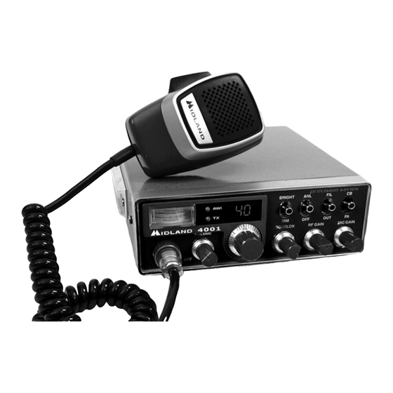
Page 8: Midland Model 4001 Cb Operating Controls
Midland MODEL 4001 CB Operating controls FRONT PANEL CONTROLS ON/OFF VOLUME: In the off position your transceiver power is off. Turn this control clockwise to switch on the unit and adjust the volume. SQUELCH CONTROL: Adjust this control until background noise just disappears. - Page 9 MIC GAIN CONTROL: Adjust this control to suit individual voice characteristics and ambient noise conditions to provide maximum intelligibility. S/RF POWER METER: This meter is used in receiveing to indicate the relative signal strength of incoming signals. When transmitting, it shows RF power output.
-
Page 10: Back Panel
BACK PANEL ANTENNA CONNECTOR: Connect a standard 50-ohm CB antenna to this connector. EXT SP: When a speaker is connected to this jack the internal speaker is by-passed. All received signals will be heard through the external speaker. The speaker connected to the “EXT” jack should be rated at 8 ohms and 5 watts. -
Page 11: Transmitter
Power Supply ...13.8 VDC negative ground Size ……………………………………………………4-7/8”(W) x 6-1/2”(D) x 1-1/2”(H) Unit Weight…………………………………………………………………….1 lb. 10 oz. RECEIVER ( CB, 26.965-27.405 MHz ) Sensitivity at 10db S/N...0.7 uV Selectivity ...45 dB + 10 kHz Squelch range ...0.5 uV-500 uV Audio output power ...3.0 W @ 8 Ohm ( 10% distortion) Distortion at 1000 mV ...3% Audio frequency response ...400-2400 Hz Intermediate frequency ...I °... -
Page 12: Limited Warranty
___________________________________________________________________ LIMITED WARRANTY. Midland Radio will repair or replace, at its option without charge, your MODEL 4001 CB transceiver which fails due to a defect in material or workmanship within three years following the initial consumer purchase.