Table of Contents
Advertisement
Service Manual
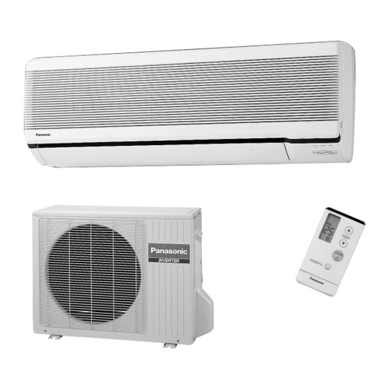
CS-G93KE / CU-G93KE
CS-G123KE / CU-G123KE
Contents
Features .......................................................... 1
Functions ................................................... 2 - 6
Product Specifications ............................. 7 - 10
Dimensions ............................................ 11 - 12
Refrigeration Cycle Diagram ......................... 13
Block Diagram ............................................... 14
Wiring Diagram ...................................... 15 - 16
Operation Details ................................... 17 - 47
Installation Information .......................... 48 - 49
Servicing Information ............................. 50 - 62
Technical Data ....................................... 63 - 64
Exploded View ......................................... 65, 68
Replacement Parts List ..................... 66, 67, 69
Electronic Parts List ............................... 70 - 71
ORDER NO. MAC9812043C2
Room Air Conditioners
© 1998 Matsushita Air-Conditioning Corp. Sdn. Bhd.
(183914D)
All rights reserved. Unauthorized copying and distribu-
tion is a violation of law.
Advertisement
Table of Contents

Related Manuals for Panasonic CS-G93KE


Summary of Contents for Panasonic CS-G93KE
-
Page 1: Table Of Contents
ORDER NO. MAC9812043C2 Service Manual Room Air Conditioners CS-G93KE / CU-G93KE CS-G123KE / CU-G123KE Contents Features ............1 Functions ........... 2 – 6 Product Specifications ......7 – 10 Dimensions ..........11 – 12 Refrigeration Cycle Diagram ......13 Block Diagram ..........14 Wiring Diagram ........ -
Page 2: Features
CS-G93KE WARNING This service information is designed for experienced repair technicians only and is not designed for use by the general public. It does not contain warnings or cautions to advise non-technical individuals of potential dangers in attempting to service a product. Products powered by electricity should be serviced or repaired only by experienced professional technicians. -
Page 3: Functions
CS-G93KE Functions Remote Control OFF / ON TEMP Operation OFF / ON Room Temperature Setting • Temperature Setting (16˚C to 30˚C). MODE Operation Mode Selection TIMER ON OFF Timer Operation Selection • Automatic Operation Mode • Heating Operation Mode HEAT •... - Page 4 Test Run Operation • Used when test running or servicing. • Compressor operation: rated frequency Timer Operation * * * * * Cooling: 50Hz (CS-G93KE), 70Hz (CS-G123KE) Heating: 71Hz (CS-G93KE), 90Hz (CS-G123KE) Powerful Mode * * * * * Operation Indication Lamps •...
- Page 5 CS-G93KE CS-G93KE CS-G93KE Functions Functions Functions Outdoor Unit COOLING/SOFT DRY OPERATION HEATING OPERATION AUTOMATIC OPERATION Deodorizing Control * * * * * Anti-Cold Draft Control * * * * * Room Temperature Control * * * * * Outdoor Fan Motor...
- Page 6 CS-G93KE CS-G93KE CS-G93KE Product Specifications Product Specifications Product Specifications Unit CS-G93KE CU-G93KE Unit CS-G123KE CU-G123KE Unit CS-G93KE CU-G93KE Heat Description Evaporator Condenser 2.6 (0.70 - 3.00) 3.45 (0.74 - 4.00) Cooling Capacity Cooling Capacity Exchanger Tube material Copper Copper Btu/h...
-
Page 7: Product Specifications
CS-G93KE Product Specifications Unit CU-G123KE CS-G123KE Description Evaporator Condenser Heat Tube material Copper Copper Exchanger Fin material Aluminium Aluminium Fin Type Slit Fin Corrugated Fin Row / Stage (Plate fin configuration, forced draft) 2/14 2/20 Size (W × H × L) 693.5 ×... -
Page 8: Dimensions
CS-G93KE Dimensions CS-G93KE / CS-G123KE <Front View> Unit : mm Air intake direction Air outlet Right piping hole Left piping direction hole Remote control transmitter GAS SIDE <Back View> LIQUID SIDE TEMP DRAIN PORT POWERFUL Relative position between the indoor unit and the installation plate <Front View>... - Page 9 CS-G93KE Dimensions CU-G93KE / CU-G123KE Space necessary for installation (52) 10 cm 10 cm 100 cm Anchor Bolt Pitch 323 x 500 High Pressure 2-Ways Valve Low Pressure 3-Ways Valve (323) – 12 –...
-
Page 10: Refrigeration Cycle Diagram
CS-G93KE Refrigeration Cycle Diagram CS-G93KE / CU-G93KE CS-G123KE / CU-G123KE INDOOR OUTDOOR CHECK VALVE HEAT EXCHANGER TEMP. 2-WAY SENSOR VALVE INTAKE AIR TEMP. OUTDOOR AIR HEAT SENSOR TEMP. EXCHANGER SENSOR TEMP. SENSOR HEAT EXCHANGER (EVAPORATOR) HEAT EXCHANGER (CONDENSER) 4-WAY VALVE... -
Page 11: Block Diagram
CS-G93KE Block Diagram – 14 –... -
Page 12: Wiring Diagram
CS-G93KE Wiring Diagram CS-G93KE / CU-G93KE POWER SUPPLY CORD STANBY CONTROLLER REMOTE CONTROLLER PUMP DOWN SW. ON-OFF SW. NO. SW. AUTO SW. (TEST RUN) ELECTRONIC CONTROLLER FUSE T 3.15A L 250V WIRELESS REMOTE CONTROL ELECTRONIC CONTROLLER (RECEIVER) CN-RCV (W) CN-STM2 (Y) - Page 13 CS-G93KE Wiring Diagram CS-G123KE / CU-G123KE POWER SUPPLY CORD STANBY CONTROLLER REMOTE CONTROLLER PUMP DOWN SW. ON-OFF SW. NO. SW. AUTO SW. (TEST RUN) ELECTRONIC CONTROLLER FUSE T 3.15A L 250V WIRELESS REMOTE CONTROL ELECTRONIC CONTROLLER (RECEIVER) CN-RCV (W) CN-STM2 (Y)
-
Page 14: Operation Details
CS-G93KE Operation Details A. FUNCTIONS 1. TEMPERATURE SHIFT Once the operation starts, the remote control setting temperature will be shifted internally based on the setting fan speed and outdoor air temperature. In addition, if Sleep Mode or Powerful Mode are set, the temperature shift will be carried out. -
Page 15: Cooling Operation
CS-G93KE Operation Details 2. COOLING OPERATION A. Room Temperature Control (i) When the remote control setting temperature is less than 24°C. Cooling Compressor Operation Frequency (Hz) Intake air temp. – 64 (Fc max) or 50 64 (Fc max) or 50... - Page 16 CS-G93KE Operation Details B. Deodorizing Control • This control is available during automatic fan speed for Cooling and Soft Dry Operation. It is not available during anti-freezing control. Deodorizing Status 6, 7, 6, 7,… Compressor Time (second) ……… Indoor Fan Speed Auto ………...
-
Page 17: Soft Dry Operation
CS-G93KE Operation Details 3. SOFT DRY OPERATION A. Room Temperature Control At the start of operation, cooling operation is running until the intake air temperature is 0.5°C higher than internal setting temperature, then the operation will shift to Soft Dry with indoor fan speed SLo. - Page 18 CS-G93KE Operation Details B. Deodorizing Control • This control is available during automatic fan speed for Cooling and Soft Dry Operation. It is not available during anti-freezing control. Deodorizing Status 4, 5, 4, 5,… Compressor Time (second) ……… Fan Speed ………...
-
Page 19: Heating Operation
CS-G93KE Operation Details 4. HEATING OPERATION A. Room Temperature Control • During heating operation, the room temperature control depends on intake air temperature and internal setting temperature. Basically it can be divided into 2 periods as shown below: Stabilized Intake air temp. – internal setting temp. - Page 20 CS-G93KE Operation Details CS-G123KE Heating Operation Compressor Operation Frequency (Hz) Transition Period Stabilized Period Remote Control Setting Temp. 21°C ~ 30°C 16°C ~ 30°C 16°C ~ 20°C Intake air temperature – Internal setting temperature Comp Off Comp Off Comp Off...
- Page 21 CS-G93KE Operation Details CS-G123KE Heating Operation Compressor Operation Frequency (Hz) Transition Period Stabilized Period Remote Control Setting Temp. 16°C ~ 30°C 16°C ~ 20°C 21°C ~ 30°C Intake air temperature – Internal setting temperature Comp Off Comp Off Comp Off...
- Page 22 CS-G93KE Operation Details B. Anti Cold Draft Control (i) Indoor Fan Control Indoor fan speed and airflow direction varies in accordance to the indoor heat exchanger temperature as shown below: a. Manual Fan speed control (Manual Airflow Direction Control) (Auto Airflow Direction Control)
- Page 23 • At the start of heating operation, the indoor fan stops and compressor operates at Fhmax frequency 99Hz (CS-G93KE) or 115 Hz (CS-G123KE). This is to heat up the indoor heat exchanger in order to avoid cold air discharged. •...
- Page 24 CS-G93KE Operation Details Deice Operation Time Chart Outdoor Heat Exchanger Temperature (°C) Deice Operation Ending Signal 30 sec 30 sec Deice max 11 min Heating Heating Operation Operation –6 Deice Operation –7 Starting Signal –9 –11 99Hz (CU-G93KE) Compressor operating...
- Page 25 CS-G93KE Operation Details D. Standby Control (a) The purpose of Standby Control is to warm up the compressor when outdoor temperature is low. The standby control will be activated when all of the followings occur. (i) Main power switch is ON.
- Page 26 CS-G93KE Operation Details 5. FAN OPERATION This operation is to enable the fan operation without compressor running. Timer operation is valid for fan operation. 6. AUTOMATIC OPERATION When the Automatic mode is selected, the operation mode is decided in accordance to remote control setting temperature, intake air temperature and outdoor air temperature.
- Page 27 CS-G93KE Operation Details (c) When setting temperature of remote control is 23°C ~ 26°C. (d) When setting temperature of remote control is 27°C and above. – 30 –...
- Page 28 CS-G93KE Operation Details • When the operation mode is changed over, the value for t1, t2 and t3 are shifted as follows: Cooling/Soft dry → Heating: –2°C Heating → Cooling/Soft dry: +2°C • When the indoor intake air temperature is lower than 16°C, heating operation is immediately started.
- Page 29 CS-G93KE CS-G93KE – 33 – – 32 –...
- Page 30 CS-G93KE CS-G93KE Operation Details Operation Details (a) Cooling Automatic Fan Speed (c) Cooling Operation at SHi Speed During Cooling operation, Indoor Fan speed is set at SHi when the following conditions occur: The Automatic Fan Speed for cooling operation is shown as below: •...
-
Page 31: Airflow Direction
CS-G93KE Operation Details 9. AIRFLOW DIRECTION A. Vertical Airflow Direction • Vane angle setting Vane angle Operation 33° Heating Airflow direction auto Indoor heat exchanger temperature 70° 15° Airflow direction manual – 46° 13° 33° 57° 70° – 7° ~ 36°... - Page 32 CS-G93KE Operation Details (a) Vertical Airflow Direction Manual By pressing the remote control vertical airflow direction setting switch, the vane will move to the indicated angle (1, 2, 3, 4, 5) as shown in the table. When the remote control OFF/ON switch is pressed to stop the unit, the vane will move to the Close position.
-
Page 33: Quiet Operation
CS-G93KE Operation Details (b) Manual Horizontal vane angle setting • By pressing the remote control horizontal airflow direction setting switch, the vane will move to the indicated position (1, 2, 3, 4, 5, 6, 7) as shown in the table. -
Page 34: Powerful Mode Operation
CS-G93KE Operation Details 11. POWERFUL MODE OPERATION When the powerful mode is selected, the internal setting temperature will shift to achieve the setting temperature quickly. (a) Cooling Operation Internal setting temperature ↓ –4°C ↑ When powerful button is pressed (b) Soft Dry Operation... - Page 35 CS-G93KE Operation Details (b) Heating Operation • When the sleep button is pressed, the remote control setting temperature will decrease 2°C after 1 hour or when the remote control setting temperature is reached. After another hour, 3°C will be decreased again.
- Page 36 CS-G93KE Operation Details 15. POWER MONITOR DISPLAY POWERFUL POWER SLEEP TIMER HIGH P O W E R MONITOR Power Monitor LED lights on when the compressor is in operation. The number of the LED lights on is in accordance to the compressor operating frequency.
- Page 37 CS-G93KE Operation Details B. PROTECTION 1. PROTECTION CONTROL FOR ALL OPERATIONS Time Delay Safety Control • The compressor is not restarted for 3 minutes after stop of compressor. 30 Second Forced Operation • Once the compressor is ON, it will not turn OFF for 30 seconds. However, it is turned off by remote control or Automatic switch.
- Page 38 CS-G93KE Operation Details 2. DC Peak Current Control When the electric current to the IPM (power transistor) exceeds the set value, DC 27 ± 4A, the compressor • stops. The compressor restarts after 3 minutes. • If within 30 seconds the set value is exceeded again, the compressor will stop for 1 minute. If this condition repeats for 7 times, all indoor and outdoor relays will be turned off;...
- Page 39 Min 33Hz Min 36Hz Low Power Supply Voltage Protection When the DC voltage supplied to IPM (Power transistor) is reduced to 169 ± 5V (CS-G93KE) or 160 ± 5V • (CS-G123KE) the compressor stops and restarts after 3 minutes. If within 30 seconds after restarting of compressor, the DC voltage is reduced to 169 ± 5V (CS-G93KE) or •...
- Page 40 3. Remote control setting temperature is less than 25°C. • During anti-dew formation control, compressor operates at 36 Hz (CS-G93KE) or 44 Hz (CS-G123KE) and airflow direction vane move slightly (as shown in Airflow Direction Control). Indoor fan speed will shift as...
- Page 41 CS-G93KE Operation Details Anti-Fog Discharge Control • The compressor operating frequency is regulated by operation time to prevent fog discharged from indoor unit as shown in the table below. Compressor operating frequency 0 ≤ T < 30 Operation 50Hz 70Hz Time, T (min) 30 ≤...
- Page 42 CS-G93KE Operation Details 3. PROTECTION CONTROL FOR HEATING OPERATION Intake Air Temperature Control • When the intake air temperature is 10°C or above and remote control setting fan speed is less than Me-, the compressor operates maximum at 71 Hz (CU-G93KE) or 90 Hz (CU-G123KE).
-
Page 43: Installation Information
Remote control Vinyl tape Battery Vinyl tape Air purifying filter Accessories: Flaring piping kit CZ-3F5, 7AEN (CS-G93KE) CZ-4F5, 7AEN (CS-G123KE) SELECT THE BEST LOCATION INDOOR UNIT • There should not be any heat source or steam near the unit. •... - Page 44 CS-G93KE Installation Information Indoor / Outdoor unit installation diagram Length of power supply cord Piping direction Attention not to bend up drain hose (Front side) about 1.1 m about 1.8 m Right Right rear < < < < Left Left...
-
Page 45: Servicing Information
CS-G93KE Servicing Information A. TROUBLESHOOTING 1. RATED FREQUENCY OPERATION During troubleshooting and servicing, rated compressor operating frequency must be obtained in order to check the specification and technical data. Below are the methods used to obtain rated compressor operating specification. -
Page 46: Refrigeration Cycle System
CS-G93KE Servicing Information 2. TROUBLESHOOTING AIR CONDITIONER Refrigeration cycle system In order to diagnose malfunctions, make sure that Normal Pressure and Outlet Air Temperature (Standard) there are no electrical problems before inspect- Gas pressure Outlet air ing the refrigeration cycle. Such problems include MPa (kg/cm temperature (°C) - Page 47 CS-G93KE Servicing Information 1. Relationship between the condition of the air conditioner and pressure and electric current Cooling Mode Heating Mode Condition of the air Electric Electric Low Pressure High Pressure Low Pressure High Pressure conditioner current during current during...
- Page 48 CS-G93KE Servicing Information B. SELF DIAGNOSIS DISPLAY The diagnostic display can be seen on the receiver of the Front Grille. When an abnormality occurs, the unit automatically stops, and the TIMER LED blinks to indicate a malfunction. At the same time, the type of abnormality will be indicated on the receiver as shown in the diagram below. Providing this information reduces the time spent in diagnosing procedures.
- Page 49 CS-G93KE Servicing Information Abnormality Temporary Diagnosis Abnormality / Protection control Primary location to verify Judgement operation display Indoor / outdoor abnormal 1 min after – • Internal / external cable connections communication • Indoor / Outdoor PCB starting operation Indoor intake air temperature •...
- Page 50 CS-G93KE Servicing Information (a) Current Transformer Defective When the Current Transformer (CT) is an open circuit, total running current is less than 1.88 A and the indicated frequency is 53 Hz (CU-G93KE) or 74 Hz (CU-G123KE) or above. If this condition continues for 20 seconds, the abnormality signal is sent from outdoor to indoor after 3 minutes of operation and [H16] is displayed.
- Page 51 CS-G93KE Servicing Information Reset Button C. REMOTE CONTROL Remote Control Reset When the batteries are inserted for the first time, or the batteries are replaced, all the indications will blink and the remote control might not work. If this happens, remove the back cover of the...
- Page 52 CS-G93KE Servicing Information D. DISASSEMBLY OF PARTS Indoor Control Board Removal Procedure 1. Remove the Front Grille Fig. 1 Fig. 2 3 Press the 2 tabs 2 Remove the Front Grille 1 Remove caps and screws 2. Remove the Indoor Control Board Fig.
- Page 53 CS-G93KE Servicing Information Removal of Electronic Controller Procedure Fig. 5 Fig. 6 2 Remove the particular plate 1 Remove screw 2 Remove the particular plate Fig. 8 Fig. 7 4 Slide to remove PCB cover 3 Remove screw Fig. 9 Fig.
- Page 54 CS-G93KE Servicing Information Indoor Fan Motor Removal Procedure Fig. 12 Fig. 11 2 Press down 1 Remove screw Tabs 1 Remove screw 2 Press up Fig. 13 Fig. 14 3 Remove the front cover 4 Remove the side cover Fig. 15...
- Page 55 CS-G93KE Servicing Information Cross Flow Fan Removal Procedure 1. Remove Discharge Grille Fig. 16 1 Remove the Discharge Grille Remove Cross Flow Fan Fig. 18 Fig. 17 2 Remove the bushing 2 Remove the screw 3 Release the slot of indoor heat exchanger from the chassis Fig.
- Page 56 CS-G93KE Servicing Information Outdoor Electronic Controller Removal Procedure WARNING • Be save to return the wiring to its original position • There are many high voltage compo- nents within the heat sink cover so never touch the interior during operation. Wait at least two minutes after power has been turned off.
- Page 57 CS-G93KE Servicing Information Propeller Fan Removal Procedure Fig. 24 Fig. 25 2 Remove the propeller fan 1 Remove the nut (clockwise direction) Outdoor Fan Motor Removal Procedure Fig. 27 Fig. 26 3 Remove the connector 4 Remove 4 screws Fig. 28 5 Remove the Outdoor Fan Motor –...
-
Page 58: Technical Data
CS-G93KE Technical Data L L L L L Operation characteristics CS-G93KE / CU-G93KE • Cooling Characteristic • Piping Length Characteristic (Cooling) 230V 230V 0.62 0.61 0.62 0.60 0.60 0.59 0.58 0.56 0.58 OUTDOOR AIR TEMPERATURE (°C) PIPING LENGTH (m) [Condition] Room temperature: 27/19°C [Condition] Room temperature: 27/19°C... - Page 59 CS-G93KE Technical Data L L L L L Operation characteristics CS-G123KE / CU-G123KE • Cooling Characteristic • Piping Length Characteristic (Cooling) 230V 230V 0.58 0.57 0.57 0.56 0.56 0.55 0.55 0.54 0.54 0.53 OUTDOOR AIR TEMPERATURE (°C) PIPING LENGTH (m) [Condition] Room temperature: 27/19°C...
-
Page 60: Exploded View
CS-G93KE Exploded View CS-G93KE / CS-G123KE < & " > & (Note) : The above exploded view is for the purpose of parts disassembly and replacement. The non-numbered parts are not kept as standard service parts. – 65 –... -
Page 61: Replacement Parts List
CS-G93KE CS-G93KE Replacement Parts List Replacement Parts List <Model: CS-G93KE / CS-G123KE> <Model: CS-G93KE / CS-G123KE> REMARKS DESCRIPTION & NAME CS-G93KE CS-G123KE REMARKS DESCRIPTION & NAME CS-G93KE CS-G123KE CHASSY COMPLETE CWD50C338 INSTALLATION INSTRUCTIONS CWF61696 FAN MOTOR CWA98244 INSTALLATION PLATE CWH36157... - Page 62 CS-G93KE CS-G93KE Exploded View Replacement Parts List <Model: CU-G93KE / CU-G123KE> CU-G93KE / CU-G123KE DESCRIPTION & NAME CU-G93KE CU-G123KE REMARKS CHASSY COMPLETE CWD50K660A FAN MOTOR BRACKET CWD54254 CWD54255 SCREW - FAN MOTOR BRACKET FAN MOTOR CWA95384 CWA95380 SCREW - FAN MOTOR...
-
Page 63: Electronic Parts List
CS-G93KE Electronic Parts List <Model : CWA741405 / CWA741406> Indoor PCB SYMBOL DESCRIPTION & NAME PART NO. BUZZER A48040 D1, D2, D4, D5, D7, D8 DIODE A541SS355T D3, D6, D9 DIODE A54D1F60 DIODE BRIDGE A54D3SBA60F1 FUSE FUSE XBA2C31TR0 INTERGRATED CIRCUIT... - Page 64 CS-G93KE Electronic Parts List <Model : CWA73C312 / CWA73C311> Outdoor PCB SYMBOL DESCRIPTION & NAME PART NO. C-FM CAPACITOR -FM A31735 CURRENT TRANSFORMER A40260 DIODE A54AU02ZV0 D17, D18, D20 DIODE A54RA15-06V3 DIODE A54RA15-10V3 D2, D3, D4, D5, D8 DIODE A54RA22-04V3...
- Page 65 CS-G93K/G123K CS-G93K/G123K CS-G93K/G123K CS-G93K/G123K ELECTRONIC CIRCUIT DIAGRAM <INDOOR UNIT> • CS-G93KE • CS-G123KE MAIN SWITCH RY-PWR TO OUTDOOR AC 230V 50Hz A49AF32102TL 33µ 100µ 0.01µ 10µ A55DA143XKTX – 100k – – 6.3V 102°C CLOCK PULSE THEROMAL GENERATION 4.7k FUSE A55DC143XKTX 1.5µ...
- Page 66 CS-G93K/G123K CS-G93K/G123K CS-G93K/G123K CS-G93K/G123K TIMER TABLE <INDOOR> TIMER TABLE <OUTDOOR> ELECTRONIC CIRCUIT DIAGRAM How to use electronic circuit diagram • Test mode Test mode REMOTE CONTROL Before using the circuit diagram, read the following carefully. Name Time When test point Name Time When test point...
- Page 67 CS-G93K/G123K CS-G93K/G123K CS-G93K/G123K ELECTRONIC CIRCUIT DIAGRAM <OUTDOOR UNIT> • CU-G93KE • CU-G123KE Fig. 3 OUTDOOR TERMINAL FUSE Fig. 3 250V, 20A AC 230V DIODE FOR CU-G123KE ONLY Outdoor Air/Outdoor AC18-23V REACTOR DIODE Heat Exchanger Temp. AC230V – REACTOR CAPACITOR Outdoor Air –...
- Page 68 CS-G93K/G123K CS-G93K/G123K CS-G93K/G123K PRINT PATTERN INDOOR UNIT PRINTED CIRCUIT BOARD OUTDOOR UNIT PRINTED CIRCUIT BOARD • • • MAIN INDICATOR MAIN...
- Page 69 Printed in Malaysia MACC P981203500YH...