Table of Contents
Advertisement
SERVICE
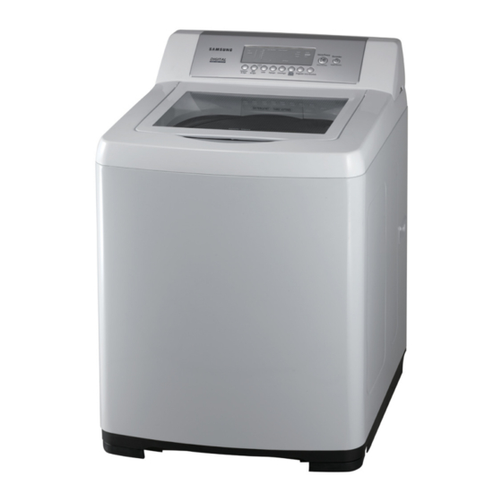
PRODUCT IMAGE
Refer to the service manual in the itself (http://itself.sec.samsung.co.kr/) for the more information.
WASHING MACHINE
FULLY AUTOMATIC
BASIC MODEL : WA17L9W
MODEL
MODEL CODE : SW85ASPIW1/XSA
Manual
THE FEATURE OF PRODUCT
1. Digital Fuzzy Logic Control
2. Opaque Steel Door
3. Water Saving Tub
4. Magic Filter
5. Centerjet Pulsator
6. Adjustable Leg
: SW85ASP/SW82ASP
SW85ASPIW1/YMI
SW82ASPIW/XSA
SW82ASPIW/YMI
Advertisement
Table of Contents

Related Manuals for Samsung SW85ASP


Summary of Contents for Samsung SW85ASP
- Page 1 PRODUCT IMAGE THE FEATURE OF PRODUCT 1. Digital Fuzzy Logic Control 2. Opaque Steel Door 3. Water Saving Tub 4. Magic Filter 5. Centerjet Pulsator 6. Adjustable Leg Refer to the service manual in the itself (http://itself.sec.samsung.co.kr/) for the more information.
-
Page 2: Table Of Contents
CONTENTS 1. PRECAUTIONS 1-1. SAFETY PRECAUTIONS .........................1-1 1-2. PRECAUTIONS UPON INSTALLATION ..................1-2 2. PRODUCT SPECIFICATIONS 2-1. THE FEATURE OF PRODUCT ......................2-1 2-2. SPECIFICATIONS OF PRODUCT ....................2-2 2-3. THE COMPARATIVE SPECIFICATIONS OF PRODUCT ..............2-3 2-4. OPTION SPECIFICATIONS ......................2-4 3. OPERATING INSTRUCTIONS AND INSTALLATION 3-1. - Page 3 CONTENTS 8. PARTS LIST (SA) ............................8-1 9. BLOCK DIAGRAM ..........................9-1 10. WIRING DIAGRAM ..........................10-1 11. PCB DIAGRAM ...........................11-1 12. SCHEMATIC DIAGRAMS .........................12-1 13. CIRCUIT DESCRIPTIONS 13-1. OVERALL SYSTEM DIAGRAM ....................13-1 13-2. AC INPUT & POWER CIRCUIT ....................13-1 13-3. DRIVING SYSTEM CIRCUIT ......................13-2 13-4.
-
Page 4: Precautions
1. PRECAUTIONS 1-1. SAFETY PRECAUTIONS 1. Do not allow the customer to repair product. The person may be injured or the product life may be shortened. 2. Be sure to unplug the power cord before starting to service (especially when servicing the electrical parts). ... -
Page 5: Precautions Upon Installation
1-2. PRECAUTIONS UPON INSTALLATION 1-2-1. Instruction for Installation Environment 1. Install the washing machine on a solid and level floor. 2. Place the machine at least 10cm away from the wall. 3. Placement on an inclined, weak or rough floor may cause abnormal trembling. 1-2-2. -
Page 6: Connecting The Water Supply Hose
1-2-4. Connecting the Drain Hose 1. After pressing the joint ring (a), insert the drain hose (b) in the drain outlet. (same as pump model) 2. Install the drain hose about 80~100cm above the ground. (for pump model) 1-2-5. Connecting the water supply hose 1. - Page 7 1-2-6. Positioning the Drain Hose (pump model) Take out the cap-hose and connect the outlet-hose. Be sure to join tightly the drain hose into the drain-outlet on the back of the machine. Be sure to join tightly the drain hose into the drain-outlet on the side of the machine. Install the drain hose in the position of about 90~100cm above the ground.
-
Page 8: Product Specifications
2. PRODUCT SPECIFICATIONS 2-1. THE FEATURE OF PRODUCT WATER SUPPLY HOSE RED-HOT WATER DRAIN HOSE WATER SUPPLY HOSE WHITE-COLD WATER DETERGENT BOX MAGIC FILTER POWER PLUG BLEACH INLET FABRIC SOFTENER DISPENSER HEIGHT ADJUSTING LEG... -
Page 9: Specifications Of Product
2-2. SPECIFICATIONS OF PRODUCT Classifications Specifications Model SW85ASP/SW82ASP Washing Capacity 8.5kg Washing Method Stirring Type Rated Voltage 230~30V/50Hz Wash 550W Power Consumption Spin 310W Maximum 92 ℓ High 78 ℓ Standard Medium 62 ℓ Water Level Med-Low 48 ℓ Extra Low 32 ℓ... -
Page 10: The Comparative Specifications Of Product
2-3. THE COMPARATIVE SPECIFICATIONS OF PRODUCT SW85ASPIW1/XSA SW82ASPIW/XSA Model SW85ASPIW1/YMI SW82ASPIW/YMI Washing Capacity 8.5kg 8.5kg Rated Voltage 230~40V/50Hz 230~40V/50Hz Water Supply Hot+Cold+Rinse Hot+Cold+Rinse Basket Type All Stainless All Stainless Control Panel Type Mirror + Button Inlay Door Steel Steel Color Neat White Neat White Weight... -
Page 11: Option Specifications
2-4. OPTION SPECIFICATIONS Item Item Name CODE.NO REMARK DC91-10229E ASSY-HOSE WATER DC91-10229F ASSY-HOSE DC97-00139C DRAIN(O) MANUAL- DC68-02340* BOOK... -
Page 12: Operating Instructions And Installation
3. OPERATING INSTRUCTIONS AND INSTALLATION 3-1. EACH KEY AND DISPLAY �ote : �he real control panel has the same layout and ��unction as the a�o�e figure’s e�pression�� 3-2. FUNCTION OF CONTROL KEYS 1. PROGRAM KEY (1) Before the initial start key is entered or during the pause mode, each pressing of this key shows the selectable Programs as in the order below. - Page 13 (6) Function �a�le ��or Programs ��������/ ������ �������� SENSOR ������ ����� ����� ���� ���� ������ ������� ��� 6~30 min 6~30 min 6~30 min 6~30 min 1~15 min 1~15 min ���X������ 20 min 15 min 20 min 18 min 5 min 5 min ����...
- Page 14 (9) �uring the operation o�� any program, e�ery press o�� the manual control key a��ter pressing the P���� key may change the operating time o�� each manual ��unction�� ��) �hen the �P�� key is pressed, the spin time o�� “5 ����” is displayed�� ��� you sequentially press the �P��...
- Page 15 2. WATER SUPPLY KEY (1) This key is valid except for error cases. (2) This key-in changes the mode as follows. Cold Water �� �ot�Cold Water �� �ot Water �� �ot�Cold Water �� �ot Water �ot�Cold Water �� �ot Water ��...
- Page 16 4. WATER LEVEL KEY (1) The WATER LEVEL key is always valid except for error cases as below. * Error: - Water Supply Error - Drain Error - Water sensing error (2) Pressing the Water Level key shows the options in the order as below. Middle →...
-
Page 17: Main Functions
3-3. MAIN FUNCTIONS 1. WATER SUPPLY (1) The water supply function of each process opens the corresponding water valve ON until the selected water level is fulfilled. (2) Water supply valve is open for the water supply function of each process as below. Selected Wate Wash Rinse... - Page 18 2. INTERMITTENT SPINNING (1) Opening the door while the intermittent spin is in operation stops spinning and generates door open alarm (door open melody 5 times). (2) If the door is closed while the door open alarm is ongoing, the alarm status is terminated and 2) If the door is closed while the door open alarm is ongoing, the alarm status is terminated and proceeds to the next step in as identical order as in START�PAUSE key-in.
- Page 19 5. WATER SUPPLY FUNCTION (1) Identical as the water supply function of wash process. 6. RINSE FUNCTION (1) If a selected water level is fulfilled, the rinse function is performed. (2) Rinse time is 2 min 30 sec at 1 time for most of programs except for the following programs. (2 min for WOOL program, 1 min 30 sec for ECONO WAS�...
-
Page 20: Alignment And Adjustments
4. ALIGNMENT AND ADJUSTMENTS 4-1. ERROR MODE 4-1-1. ERROR FUNCTION 1. WATER LEVEL SENSOR ERROR (1) When the water level senser detects a frequency less than 15kHz or more than 30kHz for more than 5 seconds (2) Generates ERROR MELODY 5 times. (3) DISPLAY: ‘1E’... -
Page 21: Test Program Mode
4-2. TEST PROGRAM MODE 4-2-1. TEST MODE FUNCTION (Drive and other test) 1) How to enter. (Water level+Course+Power s/w) 2) All of the PCB display when you press three buttons. 3) If you depress the three buttons, it shows the micom model number in 2 seconds and then shows the software version. - Page 23 Memo...
-
Page 24: Assembly And Disassembly
5. ASSEMBLY AND DISASSEMBLY 5-1. TOOLS FOR DISASSEMBLY AND ASSEMBLY TOOL 10 mm Heater (1) Box driver 13 mm Motor (1), Balance (5), 2 holes of each left and right of the 19 mm shock absorber 1 Pulley hole Replaceable for the box driver. Double-ended 10, 13, 19 mm Since the bolt runs idle when the box driver is used, use the... -
Page 25: Disassembly
5-2. DISASSEMBLY 5-2-1. CAUTIONS FOR DISASSEMBLY AND REASSEMBLY 1. BEFORE SERVICING (1) When laying down the washing machine for repair, do not place the front side downwards. This may cause the following : - The round front face may be deformed. - The top-cover and the outer-case (round area) may not match. -
Page 26: Assembly
5-2-2. DISASSEMBLY Warning! To avoid risk of electrical shock, personal injury or death, disconnect the power to the washing machine. Disassembly Procedure Illustration ■ Removing the PCB Assembly 1) Remove the Screw to fix the Cover-T.C. 2) Lift up the Cover-T.C with the Control-Panel assembled. 3) Turn the Cover-T.C “up”. - Page 27 Disassembly Procedure Illustration Remarks ■ Removing the Motor 1) Remove the Back Cover. 2) Lay down the Washing Machine with the rear side facing the floor. 3) Pull out the Sound Absorption Panel. 4) Remove the Wire Housing. 5) Remove the V Belt. 6) Remove the two Bolts fastening the Motor.
- Page 28 5-3. Spin - Nut Repairing Box 5-3-1. Procedure 3. Insert the connecting rod ° and handle ± into 1. Insert the jig ® into the spin-nut - . 2. Insert the guide pin ¯ into the groove of the the sq uare box. Then turn the handle clockwise flange - shaft by rotating it to the right and left.
- Page 29 5-4. REASSEMBLY Reassembly procedures are in the reverse order of dissasembly procedures.
-
Page 30: Trouble Diagnosis
6. TROUBLE DIAGNOSIS As the washing machine which has the micom processor, is configured of the complicated structure, there might be many kind of the service call from the consumer even though there is no defect on the parts in the machine. Below information is prepared for the exact trouble diagnosis and the suitable repaire guide. -
Page 31: Trouble Diagnosis And Shooting On Main Failure
6-2. TROUBLE DIAGNOSIS AND SHOOTING ON MAIN FAILURE 6-2-1. POWER SUPPLY, DISPLAY, AND KEY SELECTION FAILURE (1) In case of no power on when you plug in the power cord and then press the POWER key No Power ON Is the rating voltage supplied ? Apply the rating voltage. - Page 32 (2) In case the unselected indicator turns on. Unselected indicator turns on. Replace defective PCB ASS`Y. (3) In case there is no beep sound and also the indicator does not turn on at any key selection. No beep sound and or no display in the indicator Turn Power S/W ON.
- Page 33 6-2-2. DRIVING UNIT FAILURE - At the below instruction, it is the case that there is no failure on the power supply and key selection. it is the diagnosis of any problem after POWER key and START key are selected and then any operation is being normally performed.
- Page 34 (2) In case the water supply does not stop and also the wash does not start. The water supply does not stop Pull out the plug. The water valve is defective. Does the water supply stop? * Remove the foreign material in the water velve.
- Page 35 (3) In case the wash starts without the water supply. Wash starts without the water supply Water Level Sensor terminal Connect terminals securely. is securely connected? Turn Power OFF and starts to Washing is going on? operate again. Replace defective PCB ASS`Y.
- Page 36 (4) In case the pusator does not rotate during washing. - This malfunction may be caused by defective contacts of the wire harness. The pulsator dose not rotate. Does the water supply stop Is the connection of the Replace the water level after filling to the specified water lwvwl sensor terminal sensor.
- Page 37 (5) In case the noise occurs during washing. Noise coccurs during washing. Does the noise occur from the inside of the washing tub? Any foreign materials stuck Remove any foreign materials. between the washing tub and the pulsator? Adjust the clearance of the pulsator. Is there noise from the clutch? Is the position of the brake...
- Page 38 (6) In case of no spinning No Spinning This is normal as designed to Is it draining? drain before spinning. Drain motor makes Improper adjustment of Pulsator blades are rotating? operating sounds? Clutch part. Repair it. V-belt tension is too strong Adjust tension of the Drain motor shows Replace Drain Motor.
- Page 39 (7) In case of no draining No Draining No pump model only Drain hose is put down? Put down the drain hose. Drain hose is bent? Position the hose properly. Press Start/Pause key 3 or 4 times in Drain ·Spin mode. Drain Motor makes operating sounds? Replace defective...
-
Page 40: Exploded View And Parts List
7. EXPLODED VIEW AND PARTS LIST 7-1. ASSY-COVER TOP [ SW82ASP ] PXXXX P0079 C0082 C0115 A0242 P0051 P0007 [ SW85ASP ] P0038 C0002 P0198 P0030 C0082 A0242 D0089 P0075 D0089 P0053 P0031 P0062 P0115 P0018 W0004... - Page 41 Location. CODE-NO DESCRIPTION SPECIFICATION Q’TY SA/SNA Remark A0242 DC64-01207A INLAY-PANEL WA17L9,PC,T1.5,W186.5,L57.3, A0242 DC64-01275A INLAY-PANEL WA15L5W,PET,T0.188,W395.6,L9 A0242 DC64-01275B INLAY-PANEL WA15L4W,PET,T0.188,W395.6,L9 A0242 DC64-01275C INLAY-PANEL WA17L7W,PET,T0.188,W395.6,L9 A0242 DC64-01275H INLAY-PANEL NEW-SKIPPY/WA14L1/4,PET,-,-, A0242 DC64-01275J INLAY-PANEL NEW-SKIPPY/WA14L2/5,PET,-,-, A0242 DC64-01275K INLAY-PANEL SKIPPY2,PET,T0.188,W395.6,L9 A0242 DC64-01275L INLAY-PANEL SKIPPY2,PET,T0.188,W395.6,L9 A0242 DC64-01275M INLAY-PANEL SKIPPY2,PET,T0.188,W395.6,L9 C0002...
- Page 42 Location. CODE-NO DESCRIPTION SPECIFICATION Q’TY SA/SNA Remark P0051 DC63-00973E COVER-T.C SKIPPY2/WA15L6WDP/XAX,ABS,-,-, P0051 DC63-00973F COVER-T.C SKIPPY2/WA15L4GDP/XAX,ABS,-,-, P0051 DC63-00973G COVER-T.C SKIPPY2/WA15L5GDP/XAX,ABS,-,-, P0051 DC63-00973H COVER-T.C SKIPPY2/WA17L9GDP/XAX,ABS,-,-, P0051 DC63-00973J COVER-T.C SKIPPY2/WA15L3WDP/XAP,ABS,-,-, P0051 DC63-00973K COVER-T.C SKIPPY2/WA15L3WDP/YCX,ABS,-,-, P0051 DC63-00973L COVER-T.C SKIPPY2/WA15L4GDP/XAP,ABS,-,-, P0051 DC63-00973M COVER-T.C SKIPPY2/WA15L4GDP/YCX,ABS,-,-, P0051 DC63-00973N COVER-T.C SKIPPY2: WA17L9GDP/XAP,ABS,-,- P0053...
-
Page 43: Assy-Tub
7-2. ASSY-TUB U0131 U0225 U0100 S0033 S0058 U0076 S0030 S0050 U0345 F0045 R0009 I0043 P0082 U0085 I0046 U0195 U0371 U0344 U0343 U0075 U0334 U0136 W0001... - Page 44 SA/SNA Remark F0045 DC97-00252J ASSY-FILTER WA11RAS3EG/XST,SAVOY-BLUE,-, F0045 DC97-09928C ASSY-FILTER Q2,SVC/2LEGS,-,- I0043 DC62-10272A HOSE-AIR PVC,ID4.5,-,-,L610,NTR,SEW-10 I0046 DC62-00092A HOSE-DRAIN SW85ASP,EPDM,L287,BLK,H R0009 DC66-40167C FLANGE-SHAFT WA13V2QMDW/XAX,ALDC8, S0030 DC97-15272A ASSY-BASKET SPIN WA17R3(12KG),MAGIC(1)/F S0030 DC97-15272B ASSY-BASKET SPIN WA15R3(10KG),MAGIC(1)/F S0030 DC97-05443X ASSY-BASKET SPIN WA17XPM,DIAMOND DRUM/MA S0030 DC97-05443Y ASSY-BASKET SPIN...
-
Page 45: Assy-Case
7-3. ASSY-CASE U0061 A0086 B0044 B0072 A0282 B0073 B0070 I0039 I0040 B0012 I0040... - Page 46 Location. CODE-NO DESCRIPTION SPECIFICATION Q’TY SA/SNA Remark A0086 DC64-01083C HANDLE POSEIDON-BIG(ASIA),PP,-,-,-,-,NEA A0282 DC61-10571B COVER-BACK SBHG1-A,-,-,-,-,-,EDGE-BEND B0012 DC97-00287K ASSY-BASE WA15X7R(X100),PUMP/10kg/LOW B0012 DC97-00287L ASSY-BASE WA17XPM(X100),PUMP/12kg/HIGH B0044 DC61-50164B LEG-LEVER POSEIDON-MAX,PP,-,KT GRY,-,- B0070 DC91-11795D ASSY-LEG SEW-D107,RUBBER-LEG+ADJUST B0072 DC61-30330B BASE WA15X7R,PP, KT GRY,10kg/LOW/PU B0072 DC61-30333B BASE WA17XPM,PP, KT GRY,12kg/HIGH/P B0073...
-
Page 47: Parts List (Sa)
8. PARTS LIST (SA) -You can search for updated part codes through ITSELF web site. URL : http://itself.sec.samsung.co.kr/ Location. CODE-NO DESCRIPTION SPECIFICATION Q’TY SA/SNA Remark J0013 DC96-01113A ASSY-PUMP DRAIN WA17R3Q3AW/YCX,-,-,110-1 J0013 DC96-01113G ASSY-PUMP DRAIN WA17R3Q3DW/XAX,-,-,110-1 P0010 DC97-07779G ASSY-SEMI COVER TOP... - Page 48 Memo...
-
Page 49: Block Diagram
9. BLOCK DIAGRAM... - Page 50 Memo...
-
Page 51: Wiring Diagram
10. WIRING DIAGRAM 10-1... - Page 52 Memo 10-2...
-
Page 53: Pcb Diagram
11. PCB DIAGRAM 11-1. MAIN PCB Item Part Name Description Motor Driving System Controls the CW & CCW motor operation. Power Relay Supplies/disconnects power when the power is turned on/off. Display System Displays the function of the operation. Key input System Activates operations depending on the user’s keystroke. - Page 54 11-2. Connector & Relay Terminals Description CN6 Component 1. Connected to water level senser (WL_1) 2. Connected to door checker (DOOR UNB) 3. Connected to water level senser (WL) 4. Connected to the ground (GND) CN1 Component CN3 Component 5. Connected to 5V (5V) Connected to Motor MR Connected to Motor ML CN5 Component...
-
Page 55: Schematic Diagrams
12. SCHEMATIC DIAGRAMS * This Document can not be used without Samsung’s authorization. 12-1... - Page 56 Memo 12-2...
-
Page 57: Circuit Descriptions
13. CIRCUIT DESCRIPTIONS 13-1. OVERALL SYSTEM DIAGRAM 13-2. AC INPUT & POWER CIRCUIT Description Generates and supplies 12V or 5V, required respectively for the AC power supply or disconnection. Operation - The AC Power 120V (or 220-240V used at any country) applied to the primary transistor will be transformed into AC12V for the secondary transistor. -
Page 58: Driving System Circuit
13-3. DRIVING SYSTEM CIRCUIT Description Controls all driving components (Valve, Drain motor, etc) by turning on/off the TRIAC of each system. Operation - MICOM outputs a high signal of 5V on pins #1~7 of IC3. - Then pins #10~16 of IC3 will be grounded (0V). - Once pins #10~16 of IC3 are grounded, TRIAC 1, 2, 3, 4, 5 and 6 turn on due to the electric potential difference to the 12V. -
Page 59: Sensor Circuit
13-4. SENSOR CIRCUIT Description Receives signals from each electric components and controls the operation. Operation - The water level sensor is connected to W/L, W/L-1 of CN6. - Certain bands of the frquency from the water level sensor is input to IC2, depending on the water level. - The water level frequency, through IC2, is transformed into a square wave before being input to MICOM 23. - Page 60 Memo 13-4...
-
Page 61: Reference Information
14. REFERENCE INFORMATION 14-1. TERMINOLOGY 1) ASSY-MAIN PCB (Imbalance Sensor) → To prevent the laundry from gathering on one side of the tube causing noise and vibration, the washing machine uses an imbalance detection device that evenly disentangles the laundry before the hydrating cycle starts. -
Page 62: Fabric Care Chart
14-2. FABRIC CARE CHART Can be ironed at 100˚C max Resistant material Do not iron Delicate fabric Can be dry cleaned using any sol- vent Item may be washed at 95˚C Dry clean with perchloride, lighter Item may be washed at 60˚C fuel, pure alcohol or R113 only Dry clean with aviation fuel, pure Item may be washed at 40˚C... -
Page 63: Q & A
14-4. Q & A Q1. What are the main features of this product? - RUST-PROOF FIBER BODY Made of durable material with rust-proof fiber body, it can endure humidity for an extended time. -TRANSPARENT WINDOW This Transparent Window is the new concept to solve the curiosity of users to see inside of washing machine while operation. - Page 64 Q6. What is the child lock? Child-Lock function This is a device to protect children from being accidentally hurt while playing with the washer. - How to start the Child-Lock function: - Press the “Power” button to go to an initial washing mode. - By pressing “Start/Hold”...
- Page 65 Samsung Electronics Co.,Ltd. -This Service Manual is a property of Samsung 416, Maetan-3Dong, Yeongtong-Gu, Suwon City, Electronics Co., Ltd. Gyeonggi-Do, Korea, 443-742 Any unauthorized use of Manual can be punished Printed in Korea under applicable International and/or domestic P/N : DC68-02669A-00 law.