Table of Contents
Advertisement
Advertisement
Table of Contents

Related Manuals for MSI G31M Series


Summary of Contents for MSI G31M Series
- Page 1 G31M Series MS-7379 ( V2.X ) Mainboard G52-73791X1...
-
Page 2: Trademarks
Copyright Notice T he material in this doc ument is the intellec tual property of M ICRO-STAR INTERNATIONAL. We take every care in the preparation of this document, but no guarantee is given as to the correctness of its contents. Our products are under continual improvement and we reserve the right to make changes without notice. -
Page 3: Safety Instructions
Safety Instructions Always read the safety instructions carefully. Keep this User’s Manual for future reference. Keep this equipment away from humidity. Lay this equipment on a reliable flat surface before setting it up. The openings on the enclosure are for air convection hence protects the equip- ment from overheating. -
Page 4: Fcc-B Radio Frequency Interference Statement
FCC-B Radio Frequency Interference Statement T h is eq uip men t h as been tested and found to c omply with the limits for a Class B digital device, pursuant to Part 15 of the FCC Rules. These limits are designed to provide reasonable protection against harmful interference in a residential installation. -
Page 5: Weee (Waste Electrical And Electronic Equipment) Statement
WEEE (Waste Electrical and Electronic Equipment) Statement... -
Page 8: Table Of Contents
Copyright Notice ... ii Trademarks ... ii Revision History ... ii Technical Support ... ii Safety Instructions ... iii FCC-B Radio Frequency Interference Statement ... iv W EEE (Waste Electrical and Electronic Equipment) Statement ... v Chapter 1. Getting Started ... 1-1 Mainboard Specifications ... - Page 9 Appendix B. Dual Core Center ... B-1 Activating Dual Core Center ... B-2 Main ... B-3 DOT (Dynamic OverClocking) ... B-5 Clock ... B-6 Voltage ... B-7 FAN Speed ... B-8 Temperature ... B-9 User Profile ... B-10 Appendix C. Intel ICH7R SATA RAID ... C-1 ICH7R Introduction ...
-
Page 10: Chapter 1. Getting Started
Getting Started Chapter 1 Getting Started Thank you for choosing the G31M Series (MS-7379 v2.X) Micro ATX m ainboard. The G31M Series m ainboards are ® based on Intel G31 & ICH7/ ICH7R (optional) chipsets for ® optimal system efficiency. Designed to fit the advanced Intel... -
Page 11: Mainboard Specifications
M S-7379 M ainboard Mainboard Specifications Processor Support ® - Intel Core 2 Quad, Core 2 Duo, Pentium and Celeron in the LGA775 package. (For the latest information about CPU, please visit http://global. msi.com.tw/index.php?func=cpuform) Supported FSB - 1333/1066/ 800 MHz Chipset - North Bridge: Intel - South Bridge: Intel... - Page 12 Getting Started RAID (optional) - SATA1~4 support RAID 0/ /1/ 10/ 5 mode Connectors Back panel - 1 PS/2 mouse port - 1 PS/2 keyboard port - 1 COM port - 1 VGA port - 4 USB 2.0 ports - 1 LAN jack - 6 flexible audio jacks On-Board Pinheaders/ Connectors - 1 Parallel port pinheader supporting SPP/EPP/ECP mode...
-
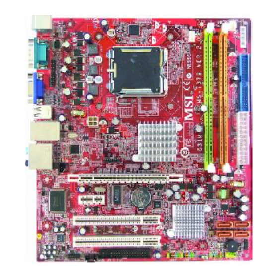
Page 13: Mainboard Layout
JCI1 P CI _E 1 Winbond W83627DHG P CI _E 2 P CI 1 P CI 2 Codec JAUD1 CD_IN1 G31M Series (MS-7379 v2.X) M-ATX Mainboard CPUFAN1 Intel B ATT Intel ICH7/ ICH7R (op tional ) JFP1 JBAT1 FDD 1... -
Page 14: Packing Checklist
Getting Started Packing Checklist MSI Driver/Utility CD SATA Cable (Optional) MSI motherboard Standard Cable for Power Cable Back IO Shield IDE Devices User’s Guide Parallel Port Bracket USB Bracket (Optional) (Optional) * The pictures are for reference only. Your packing contents may vary depending on the m odel you purchased. -
Page 15: Chapter 2. Hardware Setup
Hardware Setup Chapter 2 Hardware Setup This chapter provides you with the information about hardware setup procedures. While doing the installation, be careful in holding the components and follow the installation procedures. For some components, if you install in the wrong orientation, the components will not work properly. -
Page 16: Quick Components Guide
M S-7379 M ainboard Quick Components Guide JPW1, p.2-9 JLPT1, p.2-17 Back Panel I/O, p.2-10 PCI_E, p.2-20 JCI1, p.2-14 PCI, p.2-20 JAUD1, p.2-17 CD_IN1, p.2-15 DIMM1~2, p.2-7 CPUFAN1, CPU, p.2-3 p.2-14 FDD1, JFP1,2, JUSB1,2, p.2-12 p.2-16 p.2-18 JBAT1, p.2-19 SYSFAN1, p.2-14 IDE1, p.2-12... -
Page 17: Cpu (Central Processing Unit)
CPU (Central Processing Unit) This mainboard supports Intel ing the CPU, make sure to install the cooler to prevent overheating. If you do not have the CPU cooler, consult your dealer before turning on the computer. For the latest information about CPU, please visit http://global.msi.com.tw/index. php?func=cpuform Important Overheating... - Page 18 M S-7379 M ainboard CPU & Cooler Installation W hen you are installing the CPU, make sure the CPU has a cooler attached on the top to prevent overheating. Meanwhile, do not forget to apply some thermal paste on CPU before installing the heat sink/cooler fan for better heat dispersion. Follow the steps below to install the CPU &...
- Page 19 5. Lift the load lever up and open the load plate. 7. Visually ins pect if the CPU is seated well into the socket. If not, take out the CPU with pure vertical motion and reinstall. Hardware Setup 6. After confirming the CPU direction for correct mating, put down the CPU in the socket housing frame.
- Page 20 M S-7379 M ainboard 9. Press down the load lever lightly onto the load plate, and then se- cure the lever with the hook under retention tab. 11. Press the four hooks down to fas- ten the cooler. Then rotate the lock- ing switch (refer to the correct di- rection marked on it) to lock the hooks.
-
Page 21: Memory
Memory These DIMM slots are used for installing memory modules. For more information on compatible components, please visit http://global.msi.com. tw/index.php?func=testreport DDR2 240-pin, 1.8V 64x2=128 pin Dual-Channel: Channel A in GREEN; Channel B in ORANGE Dual-Channel mode Population Rule In Dual-Channel mode, the memory modules can transmit and receive data with two data bus lines simultaneously. -
Page 22: Installing Memory Modules
M S-7379 M ainboard Installing Memory Modules 1. The memory module has only one notch on the center and will only fit in the right orientation. 2. Insert the memory module vertically into the DIMM slot. Then push it in until the golden finger on the memory module is deeply inserted in the DIMM slot. -
Page 23: Power Supply
Power Supply ATX 24-Pin Power Connector: ATX1 This connector allows you to connect an ATX 24-pin power supply. To connect the ATX 24-pin power supply, make sure the plug of the power supply is inserted in the proper orientation and the pins are aligned. -
Page 24: Back Panel
M S-7379 M ainboard Back Panel Mouse Keyboard Serial Port M ouse/Keyboard ® The standard PS/2 mouse/keyboard DIN connector is for a PS/2 Serial Port The serial port is a 16550A high speed communications port that sends/ receives 16 bytes FIFOs. You can attach a serial mouse or other serial devices directly to the connector. - Page 25 Audio Ports These audio connectors are used for audio devices. You can differentiate the color of the audio jacks for different audio sound effects. Line-In (Blue) - Line In, is used for external CD player, tapeplayer or other audio devices. Line-Out (Green) - Line Out, is a connector for speakers or headphones.
-
Page 26: Connectors
M S-7379 M ainboard Connectors Floppy Disk Drive Connector: FDD1 This connector supports 360KB, 720KB, 1.2MB, 1.44MB or 2.88MB floppy disk drive. FDD1 IDE Connector: IDE1 This connector supports IDE hard disk drives, optical disk drives and other IDE devices. IDE1 Important If you install two IDE devices on the same cable, you must configure the... - Page 27 Serial ATA Connector: SATA1/ SATA2/ SATA3/ SATA4 This connector is a high-speed Serial ATA interface port. Each connector can connect to one Serial ATA device. SATA4 SATA3 SATA1 SATA2 Important Please do not fold the Serial ATA cable into 90-degree angle. Otherwise, data loss may occur during transmission.
- Page 28 M S-7379 M ainboard Fan Power Connectors: CPUFAN1, SYSFAN1 The fan power connectors support system cooling fan with +12V. W hen connecting the wire to the connectors, always note that the red wire is the positive and should be connected to the +12V; the black wire is Ground and should be connected to GND. If the mainboard has a System Hardware Monitor chipset on-board, you must use a specially designed fan with speed sensor to take advantage of the CPU fan control.
- Page 29 S/PDIF-Out Connector: JSP1 This connector is used to connect S/PDIF (Sony & Philips Digital Interconnect Format) interface for digital audio transmission. CD-In Connector: CD_IN1 This connector is provided for external audio input. TPM Module connector: JTPM1(optional) This connector connects to a TPM (Trusted Platform Module) module (optional) JTPM 1 Signal Description...
-
Page 30: Front Panel Connectors: Jfp1, Jfp2
M S-7379 M ainboard Front Panel Connectors: JFP1, JFP2 These connectors are for electrical connection to the front panel switches and LEDs. The JFP1 is compliant with Intel Reset Switch JFP1 Power Switch SIGNAL HD_LED + FP PWR/SLP HD_LED - FP PWR/SLP RST_SW - PWR_SW +... - Page 31 Front Panel Audio Connector: JAUD1 This connector allows you to connect the front panel audio and is compliant with ® Intel Front Panel I/O Connectivity Design Guide. JAUD1 SIGNAL MIC_L MIC_R PRESENCE# LINE out_R MIC_JD Front_JD LINE out_L LINEout_JD Parallel Port Header: JLPT1 This connector is used to connect an optional parallel port bracket.
- Page 32 M S-7379 M ainboard Front USB Connector: JUSB1 / JUSB2 This connector, compliant with Intel necting high-speed USB interface peripherals such as USB HDD, digital cameras, M P3 players, printers, modems and the like. JUSB2/1 Important Note that the pins of VCC and GND must be connected correctly to avoid possible damage.
-
Page 33: Jumpers
Jumpers Clear CMOS Jumper: JBAT1 There is a CMOS RAM onboard that has a power supply from an external battery to keep the data of system configuration. W ith the CMOS RAM, the system can auto- matically boot OS every time it is turned on. If you want to clear the system configuration, set the jumper to clear data. -
Page 34: Slots
M S-7379 M ainboard Slots PCI (Peripheral Component Interconnect) Express Slot The PCI Express slot supports the PCI Express interface expansion card. The PCI Express x 16 slot supports up to 4.0 GB/s transfer rate. The PCI Express x 1 slot supports up to 250 MB/s transfer rate. PCI (Peripheral Component Interconnect) Slot The PCI slot supports LAN card, SCSI card, USB card, and other add-on cards that comply with PCI specifications. -
Page 35: Chapter 3. Bios Setup
Chapter 3 BIOS Setup This chapter provides information on the BIOS Setup program and allows you to configure the system for optimum use. You may need to run the Setup program when: ² An error message appears on the screen during the system booting up, and requests you to run SETUP. -
Page 36: Entering Setup
M S-7379 M ainboard Entering Setup Power on the computer and the system will start POST (Power On Self Test) process. W hen the message below appears on the screen, press <DEL> key to enter Setup. Press DEL to enter SETUP If the message disappears before you respond and you still wish to enter Setup, restart the system by turning it OFF and On or pressing the RESET button. -
Page 37: Control Keys
Control Keys < > Move to the previous item < > Move to the next item < > Move to the item in the left hand < > Move to the item in the right hand <Enter> Select the item Jumps to the Exit menu or returns to the main menu from a <Esc>... -
Page 38: The Main Menu
M S-7379 M ainboard The Main Menu Standard CM OS Features Use this menu for basic system configurations, such as time, date etc. Advanced BIOS Features Use this menu to setup the items of AMI Integrated Peripherals Use this menu to specify your settings for integrated peripherals. Power M anagement Setup Use this menu to specify your settings for power management. - Page 39 Load Optimized Defaults Use this menu to load the default values set by the mainboard manufacturer specifi- cally for optimal performance of the mainboard. BIOS Setting Password Use this menu to set the password for BIOS. Save & Exit Setup Save changes to CMOS and exit setup.
-
Page 40: Standard Cmos Features
M S-7379 M ainboard Standard CMOS Features The items in Standard CMOS Features Menu includes some basic setup items. Use the arrow keys to highlight the item and then use the <PgUp> or <PgDn> keys to select the value you want in each item. Date (MM:DD:YY) This allows you to set the system to the date that you want (usually the current date). - Page 41 Device / Vender / Size It will showing the device information that you connected to the SATA connector. LBA/Large M ode This allows you to enable or disable the LBA Mode. Setting to Auto enables LBA mode if the device supports it and the devices is not already formatted with LBA mode disabled.
- Page 42 M S-7379 M ainboard System Information Press <Enter> to enter the sub-menu, and the following screen appears. This sub-menu shows the CPU information, BIOS version and memory status of your system (read only).
-
Page 43: Advanced Bios Features
Advanced BIOS Features Boot Sector Protection This function protects the BIOS from accidental corruption by unauthorized users or computer viruses. W hen enabled, the BIOS’ data cannot be changed when attempt- ing to update the BIOS with a Flash utility. To successfully update the BIOS, you’ll need to disable this Flash BIOS Protection function. - Page 44 M S-7379 M ainboard MPS Table Version This field allows you to select which MPS (Multi-Processor Specification) version to be used for the operating system. You need to select the MPS version supported by your operating system. To find out which version to use, consult the vendor of your operating system.
- Page 45 VGA Share Memory Size The system shares memory to the onboard VGA card. This setting controls the exact memory size shared to the VGA card. DVMT Mode Select This item allows you to set the mode for the graphics core.. [Fixed Mode], a fixed-size fragment of the system memory is allocated to the graphics core.
- Page 46 M S-7379 M ainboard Clearing the TPM Clearing the TPM is the process of returning the TPM to factory defaults. TPM Enable/Disable status, TPM Owner Status These items show the status of TPM (read only). 3-12...
-
Page 47: Integrated Peripherals
Integrated Peripherals USB Controller This setting allows you to enable/disable the onboard USB controller. USB Device Legacy Support Select [Enabled] if you need to use a USB-interfaced device in the operating system. Onboard LAN Controller This item is used to enable/disable the onboard LAN controller. LAN Option ROM This item is used to decide whether to invoke the Boot ROM of the LAN controller. - Page 48 M S-7379 M ainboard On-Chip IDE Controller These items allow users to enable or disable the IDE controller. PCI IDE BusMaster This item allows you to enable/ disable BIOS to used PCI busmastering for reading/ writing to IDE drives. On-Chip SATA Controller These items allow users to enable or disable the SATA controller.
-
Page 49: Power Management Setup
Power Management Setup Important S3-related functions described in this section are available only when your BIOS supports S3 sleep mode. ACPI Function This item is to activate the ACPI (Advanced Configuration and Power Management Interface) Function. If your operating system is ACPI-aware, such as W indows 2000/ XP, select [Enabled]. - Page 50 M S-7379 M ainboard Re-Call VGA BIOS from S3 Selecting [Enabled] allows BIOS to call VGA BIOS to initialize the VGA card when system wakes up (resumes) from S3 sleep state. The system resume time is short- ened when you disable the function, but system will need an AGP driver to initialize the VGA card.
- Page 51 BIOS Setup Resume by PCI-E Device W hen set to [Enabled], the feature allows your system to be awakened from the power saving modes through any event on PCIE device. Resume by RTC Alarm The field is used to enable or disable the feature of booting up the system on a scheduled time/date.
-
Page 52: Pnp/Pci Configurations
M S-7379 M ainboard PNP/PCI Configurations This section describes configuring the PCI bus system and PnP (Plug & Play) feature. PCI, or Peripheral Component Interconnect, is a system which allows I/O devices to operate at speeds nearing the speed the CPU itself uses when communicating with its special components. - Page 53 IRQ Resource Setup Press <Enter> to enter the sub-menu and the following screen appears. IRQ 3/4/5/7/9/10/11/14/15 These items specify the bus where the specified IRQ line is used. The settings determine if AMIBIOS should remove an IRQ from the pool of avail- able IRQs passed to devices that are configurable by the system BIOS.
-
Page 54: H/W Monitor
M S-7379 M ainboard H/W Monitor Chassis Intrusion The field enables or disables the feature of recording the chassis intrusion status and issuing a warning message if the chassis is once opened. To clear the warning message, set the field to [Reset]. The setting of the field will automatically return to [Enabled] later. -
Page 55: Frequency/Voltage Control
Frequency/Voltage Control Important Change these settings only if you are familiar with the chipset. Current CPU / DRAM Frequency These items show the current clocks of CPU and Memory speed. Read-only. Intel EIST The Enhanced Intel SpeedStep technology allows you to set the performance level of the microprocessor whether the computer is running on battery or AC power. - Page 56 M S-7379 M ainboard Configuration DRAM Timing by SPD Setting to [Enabled] enables DRAM CAS# Latency automatically to be determined by BIOS based on the configurations on the SPD (Serial Presence Detect) EEPROM on the DRAM module. DRAM CAS# Latency W hen the Configuration DRAM Timing by SPD sets to [Disabled], the field is adjustable.This controls the CAS latency, which determines the timing delay (in clock cycles) before SDRAM starts a read command after receiving it.
- Page 57 DRAM TWR W hen the Configuration DRAM Timing by SPD sets to [Disabled], the field is adjustable. Minimum time interval between end of write data burst and the start of a precharge command. Allows sense amplifiers to restore data to cells. DRAM TWTR W hen the Configuration DRAM Timing by SPD sets to [Disabled], the field is adjustable.
- Page 58 M S-7379 M ainboard Important 1. If you do not have any EMI problem, leave the setting at [Disabled] for optimal system stability and performance. But if you are plagued by EMI, select the value of Spread Spectrum for EMI reduction. 2.
-
Page 59: Load Fail-Safe/ Optimized Defaults
BIOS Setup Load Fail-Safe/ Optimized Defaults The two options on the main menu allow users to restore all of the BIOS settings to the default Fail-Safe or Optimized values. The Optimized Defaults are the default values set by the mainboard manufacturer specifically for optimal performance of the mainboard. -
Page 60: Bios Setting Password
M S-7379 M ainboard BIOS Setting Password W hen you select this function, a message as below will appear on the screen: Type the password, up to six characters in length, and press <Enter>. The password typed now will replace any previously set password from CMOS memory. You will be prompted to confirm the password. -
Page 61: Appendix A Realtek Audio
Realtek Audio Appendix A Realtek Audio The Realtek audio chip provides 10-channel DAC that simultaneously supports 7.1 sound playback and 2 chan- nels of independent s tereo s ound output (multiple streaming) through the Front-Out-Left and Front-Out- Right channels. -
Page 62: Installing The Realtek Hd Audio Driver
M S-7379 M ainboard Installing the Realtek HD Audio Driver You need to install the driver for Realtek aucio codec to function properly before you can get access to 2-, 4-, 6-, 8- channel or 7.1+2 channel audio operations. Follow the procedures described below to install the drivers for different operating systems. - Page 63 3. Click Next to install the Realtek High Definition Audio Driver. 4. Click Finish to restart the system. Realtek Audio Click here S el ec t t hi s option Click here...
-
Page 64: Software Configuration
M S-7379 M ainboard Software Configuration After installing the audio driver, you are able to use the 2-, 4-, 6- or 8- channel audio feature now. Click the audio icon from the system tray at the lower-right corner of the screen to activate the HD Audio Configuration. It is also available to enable the audio driver by clicking the Realtek HD Audio M anager from the Control Panel. -
Page 65: Sound Effect
Realtek Audio Sound Effect Here you can select a sound effect you like from the Environment list. Environment Simulation You will be able to enjoy different sound experience by pulling down the arrow, totally 23 kinds of sound effect will be shown for selection. Realtek HD Audio Sound Manager also provides five popular settings “Stone Corridor”, “Bathroom”, “Sewer pipe”, “Arena”... - Page 66 M S-7379 M ainboard Equalizer Selection Equalizer frees users from default settings; users may create their owned preferred settings by utilizing this tool. 10 bands of equalizer, ranging from 100Hz to 16KHz. Save The settings are saved permanently for future Enable / Disable To disable, you can tem- porarily s top the sound...
- Page 67 Frequently Used Equalizer Setting Realtek recognizes the needs that you might have. By leveraging our long experience at audio field, Realtek HD Audio Sound Manager provides you certain optimized equal- izer settings that are frequently used for your quick enjoyment. [How to Use It] Other than the buttons “Pop”...
- Page 68 M S-7379 M ainboard Mixer In the Mixer part, you may adjust the volumes of the rear and front panels individually. 1. Adjust Volume You can adjust the volume of the speakers that you pluged in front or rear panel by select the Realtek HD Audio rear output or Realtek HD Audio front output items.
- Page 69 Realtek Audio W hen you are playing the first audio source (for example: use W indows Media Player to play DVD/VCD), the output will be played from the rear panel, which is the default setting. Then you must to select the Realtek HD Audio front output from the scroll list first, and use a different program to play the second audio source (for example: use Winamp to play MP3 files).
- Page 70 M S-7379 M ainboard 3. Playback control Tool M u te You may choose to mute single or multiple volume controls or to completely mute sound output. Tool - Show the following volume controls This is to let you freely decide which volume control items to be displayed. - Advanced controls - Enable playback multi-streaming W ith this function, you will be able to have an audio chat with your friends via...
- Page 71 4. Recording control Tool Mute M u te You may choose to mute single or multiple volume controls or to completely mute sound input. Tool - Show the following volume controls This is to let you freely decide which volume control items to be displayed. - Enable recording multi-streaming Important Realtek audio allows you to record the CD, Line, Mic and Stereo Mix channels...
- Page 72 M S-7379 M ainboard Audio I/O In this tab, you can easily configure your multi-channel audio function and speakers. You can choose a desired multi-channel operation here. a. Headphone for the common headphone b. 2CH Speaker for Stereo-Speaker Output c. 4CH Speaker for 4-Speaker Output d.
- Page 73 Realtek Audio Connector Settings Click to access connector settings. Disable front panel jack detection (option) Find no function on front panel jacks? Please check if front jacks on your system are so-called AC’97 jacks. If so, please check this item to disable front panel jack detection. M ute rear panel output when front headphone plugged in.
- Page 74 M S-7379 M ainboard S/PDIF Short for Sony/Philips Digital Interface, a standard audio file transfer format. S/PDIF allows the transfer of digital audio signals from one device to another without having to be converted first to an analog format. Maintaining the viability of a digital signal prevents the quality of the signal from degrading when it is converted to analog.
- Page 75 Test Speakers You can select the speaker by clicking it to test its functionality. The one you select will light up and make testing sound. If any speaker fails to make sound, then check whether the cable is inserted firmly to the connector or replace the bad speakers with good ones.
- Page 76 M S-7379 M ainboard Microphone In this tab you may set the function of the microphone. Select the Noise Suppres- sion to remove the possible noise during recording, or select Acoustic Echo Can- cellation to cancel the acoustic echo druing recording. Acoustic Echo Cancellation prevents playback sound from being recorded by microphone together with your sound.
-
Page 77: D Audio Demo
Realtek Audio 3D Audio Demo In this tab you may adjust your 3D positional audio before playing 3D audio applica- tions like gaming. You may also select different environment to choose the most suitable environment you like. A-17... - Page 78 M S-7379 M ainboard Information In this tab it provides some information about this HD Audio Configuration utility, including Audio Driver Version, DirectX Version, Audio Controller & Audio Codec. You may also select the language of this utility by choosing from the Language list. Also there is a selection Show icon in system tray.
-
Page 79: Hardware Setup
Hardware Setup Connecting the Speakers W hen you have set the Multi-Channel Audio Function mode properly in the software utility, connect your speakers to the correct phone jacks in accordance with the setting in software utility. n 2-Channel M ode for Stereo-Speaker Output Line In Line Out (Front channels) No function... - Page 80 M S-7379 M ainboard n 4-Channel M ode for 4-Speaker Output 4-Channel Analog Audio Output Line In Line Out (Front channels) Line Out (Rear channels) No function No function A-20...
- Page 81 n 6-Channel M ode for 6-Speaker Output 6-Channel Analog Audio Output Line In Line Out (Front channels) Line Out (Rear channels) Line Out (Center and Subwoofer channel) No function Realtek Audio A-21...
- Page 82 M S-7379 M ainboard n 8-Channel M ode for 8-Speaker Output 8-Channel Analog Audio Output Line In Line Out (Front channels) Line Out (Rear channels) Line Out (Center and Subwoofer channel) Line Out (Side channels) To enable 7.1 channel audio-out function on Vista operating system, you have to install the Realtek Audio Driver.
-
Page 83: Appendix B Dual Core Center
Appendix B Dual Core Center Dual CoreCenter, the most useful and powerful utility that MSI has spent muc h researc h and ef forts to develop, helps users to monitor or configure the hard- ware status of MSI Mainboard & MSI Graphics card in windows, such as CPU/GPU clock, voltage, fan speed and temperature. -
Page 84: Activating Dual Core Center
M S-7379 M ainboard Activating Dual Core Center Once you have your Dual Core Center installed (locate the setup source file in the setup CD accompanying with your mainboard, path: Utility --> MSI Utility --> Dual Core Center), it will have an icon desktop, and a short cut path in your “Start-up”... -
Page 85: Main
Main Before using this utility, we have to remind you: only when installing the MSI V044 (V044 has to install with the version 8.26 or newer driver)/ V046 or V060 graphics card can activate the full function of this utility. If you install a graphics card of other brand, only hardware status of the MSI mainboard would be available. - Page 86 M S-7379 M ainboard AV/ Game/ Office/ Silence/ Cool MSI provides five common settings for different environments. The settings had been set to optimal values to reac h better performanc e in eac h environment. Click the button you need. Important Before clicking the AV/ Game/ Office/ Silence or Cool button, select Smooth mode or Sharp mode to decide whether you want the system to reach the...
-
Page 87: Dot (Dynamic Overclocking
DOT (Dynamic OverClocking) Dynamic Overclocking Technology is an automatic overclocking function, included in ’s newly developed Dual CoreCenter Technology. It is designed to detect the the MSI loading of CPU/ GPU while running programs, and to over-clock automatically. When the motherboard detects that the loading of CPU is exceed the default threshold for a time, it will speed up the CPU and fan automatically to make the system run smoother and faster. -
Page 88: Clock
M S-7379 M ainboard Clock In the Clock sub-menu, you can see clock status (including FSB/ CPU clock of mainboard and GPU/ memory clock of graphics card) of your system. And you can select desired value for overclocking. There will be several items for you to select for overclocking after you click to increase the clock, or click the minus sign button finally, click the Apply button to apply the values adjusted. -
Page 89: Voltage
Voltage In the Voltage sub-menu, you can see voltage status (including Vcore, memory, GPU voltage... etc.) of your system, and you can select desired value for overclocking. It will show several items to select for overclocking after you click the You can click the plus sign button button to decrease. -
Page 90: Fan Speed
M S-7379 M ainboard FAN Speed In the FAN Speed sub-menu, you can read fan status of your system. Select higher speed for better cooling effect. There are several sections for you to change the fan speed to a section after clicking increase the fan speed to a section, or click the minus sign button Or click the Default button to restore the default values. -
Page 91: Temperature
Dual Core Center Temperature In the Temperature sub-menu, you can see temperature status of your system. On the underside, it shows the graphs of the temperatures. Only the curves of the item which the button is lit up with red color will be shown. -
Page 92: User Profile
M S-7379 M ainboard User Profile In the User Profile sub-menu, click the setting button that besides the user profile bar, and the next screen will appear. Here you can define the clock/ fan speed/ voltage by your need, click the button to choose a value quickly, or click the plus / minus sign button to... - Page 93 Dual Core Center Use the draw bar to set the max system temperature. W hen the system temperature exceeds the threshold you defined, the system will pop up a warning message and shut down the system. Use the draw bar to set the minimal fan speed. When the fan speed is lower than the threshold you defined, the system will pop up a warning message.
-
Page 94: Appendix C Intel Ich7R Sata Raid
Appendix C Intel ICH7R SATA RAID The ICH7R provides a hybrid solution that combines four independent SATAII ports for support of up to four Serial ATAII (Serial ATAII RAID) drives. It offers RAID level 0 (Striping), RAID level 1 (Mirroring and Duplexing), RAID level 5 (Block Interleaved Distrib- uted Parity), RAID level 10 (A Stripe of Mirrors) and ®... -
Page 95: Ich7R Introduction
M S-7379 M ainboard ICH7R Introduction The ICH7R provides a hybrid solution that combines four independent SATAII ports for support of up to four Serial ATAII (Serial ATAII RAID) drives. Serial ATAII (SATAII) is the latest generation of the ATA interface. SATA hard drives deliver blistering transfer speeds up to 300MB/sec. -
Page 96: Bios Configuration
BIOS Configuration The Intel Matrix Storage Manager Option ROM should be integrated with the system BIOS on all motherboards with a supported Intel chipset. The Intel Matrix Stroage Manager Option ROM is the Intel RAID implementation and provides BIOS and DOS disk services. - Page 97 M S-7379 M ainboard After pressing the <Ctrl> and <I> keys simultaneously, the following window will appear: (1) Create RAID Volume Select option 1 “Create RAID Volume” and press <Enter> key. The following screen appears. Then in the Name field, specify a RAID Volume name and then press the <TAB>...
- Page 98 In the Disk field, press <Enter> key and the following screen appears. Use <Space> key to select the disks you want to create for the RAID volume, then click <Enter> key to finish selection. Then select the strip value for the RAID array by using the “upper arrow” or “down arrow”...
- Page 99 M S-7379 M ainboard Important Since you want to create two volumes (Intel Matrix RAID Technology), this default size (maximum) needs to be reduced. Type in a new size for the first volume. As an example: if you want the first volume to span the first half of the two disks, re-type the size to be half of what is shown by default.
- Page 100 (2) Delete RAID Volume Here you can delete the RAID volume, but please be noted that all data on RAID drives will be lost. Important If your system currently boots to RAID and you delete the RAID volume in the Intel RAID Option ROM, your system will become unbootable.
- Page 101 M S-7379 M ainboard (3) Reset Disks to Non-RAID Select option 3 Reset Disks to Non-RAID and press <Enter> to delete the RAID volume and remove any RAID structures from the drives. The following screen appears: Press <Y> key to accept the selection. Important 1.
-
Page 102: Installing Software
Installing Software Install Driver in Windows XP / 2000 † New Windows XP / 2000 Installation The following details the installation of the drivers while installing W indows XP / 2000. 1. Start the installation: Boot from the CD-ROM. Press F6 when the message "Press F6 if you need to install third party SCSI or RAID driver"... - Page 103 M S-7379 M ainboard Installation of Intel Matrix Storage Console The Intel Application Accelerator RAID Edition driver may be used to operate the hard drive from which the system is booting or a hard drive that contains important data. For this reason, you cannot remove or un-install this driver from the system after installation;...
- Page 104 Intel ICH7R SATA RAID The InstallShield Wizard will begin automatically for installation showed as following: Click on the Next button to proceed the installation in the welcoming window. C-11...
- Page 105 M S-7379 M ainboard The window shows the components to be installed. Click Next button to continue. After reading the license agreement in the following window, click Yes button to continue. C-12...
- Page 106 Intel ICH7R SATA RAID Select the folder in which you want the program to be installed in the following window, and click Next button to start installation. Select a program folder in the following window where you want Setup to add the program icon.
- Page 107 M S-7379 M ainboard The following window appears to show the Intel Application Accelerator RAID Edition Setup installation status. Once the installation is complete, the following window appears. C-14...
-
Page 108: Raid Migration Instructions
RAID Migration Instructions The Intel Matrix Storage Console offers the flexibility to upgrade from a single Serial ATA (SATA) hard drive to RAID configuration when an additional SATA hard drive is added to the system. This process will create a new RAID volume from an existing disk. - Page 109 M S-7379 M ainboard Create RAID Volume from Existing Disk To create a RAID volume from an existing disk, choose Action --> Create RAID Volume from Existing Hard Drive. The Create RAID Volume from Existing Hard Drive Wizard pops up to lead you for the following procedure.
- Page 110 (1) Step 1: Configure Volume Here you can configure the new RAID volume by entering the volume name, selecting the RAID level and strip size. † RAID Volume Name: A desired RAID volume name needs to be typed in where the ‘RAID_Volume1’ text currently appears above.
- Page 111 M S-7379 M ainboard RAID 10 (Mirrored Stripes) – A RAID 1 array of two RAID 0 arrays. † Strip Sizes: Select the desired strip size setting. As indicated, the optimal setting is 128KB. Se- lecting any other option may result in performance degradation. Even though 128KB is the recommended setting for most users, you should choose the strip size value which is best suited to your specific RAID usage model.
- Page 112 Intel ICH7R SATA RAID (3) Select Member Hard Drive(s) Then select the member disk (the target disk) that you wish to use and then click “- -->” to move it to the Selected field. Then click Next to continue. Please note that the existing data on the selected hard drive(s) will be deleted permanently.
- Page 113 M S-7379 M ainboard (4) Specify Volume Size Specify the amount of available array space to be used by the new RAID volume. You may enter the amount in the space or use the slider to specify. It is recommended you use 100% of the available space for the optimized usage.
- Page 114 Intel ICH7R SATA RAID (6) Start Migration The migration process may take up to two hours to complete depending on the size of the disks being used and the strip size selected. A dialogue window will appear stating that the migration process may take considerable time to complete, meanwhile a popup dialogue at the taskbar will also show the migration status.
-
Page 115: Degraded Raid Array
M S-7379 M ainboard Degraded RAID Array A RAID 1, RAID 5 or RAID 10 volume is reported as degraded when one of its hard drive members fails or is temporarily disconnected, and data mirroring is lost. As a result, the system can only utilize theremaining functional hard drive member. To re- establish data mirroring and restore data redundancy, refer to the procedure below that corresponds to the current situation. - Page 116 5. Exit Intel RAID Option ROM, and then reboot to W indows system. 6. W hen prompted to rebuild the RAID volume, click 'Yes'. 7. The Intel(R) Storage Utility will be launched. Right-click the new hard drive and select 'Rebuild to this Disk'. The 'Rebuild W izard' will be launched which will guide you through the process of rebuilding to the new hard drive.