Advertisement
Table of Contents
- 1 Table of Contents
- 2 Specifications
- 3 Replacing the DSP (HG51B155FD)
- 4 Block Diagram
- 5 Circuit Description
- 6 Wiring Diagram
- 7 Major Waveforms
- 8 PCB View and Major Check Points
- 9 Schematic Diagrams
- 10 Exploded View
- 11 IC Lead Identification and Internal Diagram
- 12 Parts List
- Download this manual
See also:
Operating Manual
Advertisement
Table of Contents

Related Manuals for Casio AT-1


Summary of Contents for Casio AT-1
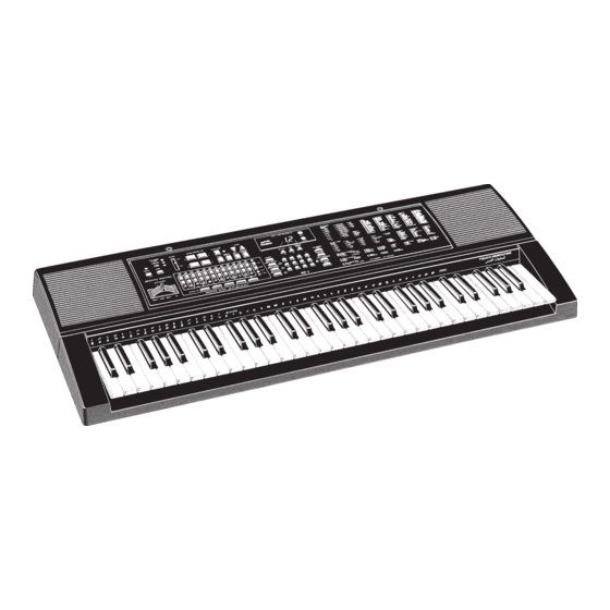
- Page 1 (without price) AT-1 ELECTRIONIC KEYBOARD INDEX...
-
Page 2: Table Of Contents
CONTENTS Specifications ......... 1 Replacing the DSP (HG51B155FD) . -
Page 3: Specifications
Oriental Scale Control: Tuning Rang: Quarter tone (±99 cents) and koma (±5 komas ) Scale Memories: Auto-Rhythms: Tempo Control: 40 to 255 Auto-Accompaniment: CASIO Chord/Fingered/Full-Range Chord Controller: Variation, Fill-In, Intro/Ending Magical Presets: BREAK BEAT FREE SESSION KEY SPLIT Digital Effects:... -
Page 4: Replacing The Dsp (Hg51B155Fd)
Electrical Current Drain with 9 V DC: 260 mA ± 20% No Sound Output 930 mA ± 20% Maximum Volume with key C3 pressed in Synth-Bass tone and effect No. E-9 Split: On, Layer: On, Oriental scale: On/Cent Song memory: Play, Volume; maximum, Touch: maximum Line Output Level (Vrms with 47 KΩ... -
Page 5: Block Diagram
BLOCK DIAGRAM 7-Seg. La ~ Lg, Lp LC1 ~ LC4 Reset IC IC104 LED driver RE5VA35AA LEDs LO0 ~ LO4 IC301/302 BA612 KO Signal LED driver Working Strage Generator Q109 ~ Q116 Keyboard KO0 ~ KO10 RAM (64K-bit) IC303/304 LSI104 TC74HC174P SRM2264LC90,10 LD0 ~ LD7... -
Page 6: Circuit Description
CIRCUIT DESCRIPTION Key Matrix Note: Each key has two contacts, the first conatct and second contact First contact 1 Second contact 2 Nomenclature of Keys F#3 G#3 A#3 C#4 D#4 F#4 G#4 A#4 C#5 D#5 F#5 G#5 A#5 C2 D2 G2 A2 C3 D3 G3 A3... -
Page 7: Button Matrix
Button Matrix Song Registration Memory Transpose/ Touch Control Demo Layer Split Tune Response Magical Tone Rhythm Preset Digital Accomp Effect G# down A down A# down B down G down ScaleMode ScaleTune B up A# up A up G# up G up Tempo Tempo... - Page 8 CPU (HD6433298A36P) The 16-bit CPU contains a 32k-bit ROM, a 1k-bit RAM, seven 8-bit I/O ports, an A/D convertor and serial interfaces. The CPU accesses to the working strage RAM, the DSP and the key touch LSI. The CPU also controls buttons, bender input, LEDs and MIDI input/output.
- Page 9 Pin No. Terminal In/Out Function 1 ~ 8 CD0 ~ CD7 In/Out Data bus 9, 10 Not used GND7 Ground (0 V) source CK16 16.384 MHz clock output VCC6 +5 V source Clock input. Connected to terminal CK16. TCKB Not used VCC1 +5 V source GND1...
- Page 10 DAC (UPD6376CX) UPD6376CX is a two-channel 16-bit Digital to Analog Convertor consisting of resistor string, output amplifier and zero offset circuit. Pin No. Terminal In/Out Function Mode selection terminal. Connected to ground. D.GND Ground (0 V) source for internal digital circuit Not used DVDD +5 V source for internal digital circuit...
- Page 11 Pin No. Terminal In/Out Function EWEB Write enable signal output for the effect RAM EA13 Not used EOEB Read enable signal output for the effect RAM VCC7 +5 V source ECEB Chip select signal output for the effect RAM 113 ~ 117 Not used VCC4 +5 V source...
-
Page 12: Filter Block
The following table shows the pin functions of the key touch LSI. Pin No. Terminal In/Out Function REQB Interrupt request. Not used. FI8 ~ FI10 2, 3, 60 ~ 63 Key input signal. Connected to + 5 V. SI8 ~ SI10 +5 V source CRDB Read enable signal... - Page 13 Power Amplifier (LA4598) The power amplifier is a two-channel amplifier with standby switch. The following figure shows the inter- nal diagram of the amplifier. Internal Diagram of LA4598 Ch2 B.S. Ch1 IN Input Power Pre-drive Ch1 OUT Amp. Amp. Amp. Ch1 N.F.
-
Page 14: Wiring Diagram
WIRING DIAGRAM JCM719-CN2M JCM719-CN1M Bender Volume L OUT JCM719-MA2M R OUT Main Volume R IN L IN DC JACK PHONE/OUTPUT JCM719-MA1M ASSIGNABLE JACK MIDI IN MIDI OUT BATT+ BATT- BATTERY COMPARTMENT M617T-KY1M M617T-KY2M — 12 —... -
Page 15: Major Waveforms
MAJOR WAVEFORMS Power switch ON F Button scan signal KO0 B Bit clock BOK 1 Main clock pulse 3 POWER signal IC304: TC74HC174AP pin 2 HD6433298A36P pin 7 UPD6376CX pin 16 HD6433298A36P pin 13 G Button scan signal KO1 2 DSP clock pulse C L/R clock WOK1 4 APO signal IC304: TC74HC174AP pin 5... -
Page 16: Pcb View And Major Check Points
14 15 PCB VIEW AND MAJOR CHECK POINTS L110 R186 L111 FB106 FB105 R187 R274 L106 C105 C171 R142 C115 R188 C122 FB104 IC103 C171 C124 C159 C101 C114 LSI105 C113 C112 Q101 C170 R120 C123 R117 C116 Q102 C179 R291 R104 LSI101... -
Page 17: Schematic Diagrams
SCHEMATIC DIAGRAMS PCB JCM719-MA1M 14 15 8 9 10 11 — 15 —... - Page 18 PCBs JCM719-CN1M, CN2M, MA2M — 16 —...
- Page 19 PCBs JCM617T-KY1M, KY2M — 17 —...
-
Page 20: Exploded View
EXPLODED VIEW 28-3 28-2 28-5 28-4 28-1... -
Page 21: Ic Lead Identification And Internal Diagram
IC LEAD IDENTIFICATION AND INTERNAL DIAGRAM UPD6376CX MAIN DAC L.OUT LRCK SUB DAC LRSEL/RSI L.REF SI/LSI SUB DAC R.REF 4/8 fs SEL MAIN DAC R.OUT D.GND A.VDD D.VDD A.GND N.C. RE5VA35AA 1 OUT M5218APR PC900V TC74HC04AP 1A 1 14 VCC 1Y 2 2A 3 2Y 4... - Page 22 TC74HC174AP BA612 CLEAR CLOCK 2SB1274 S-81350HG 2SC1740SQ 2SA933SQ 2SB1240Q,R DTA114TS — 20 —...
-
Page 23: Parts List
PARTS LIST AT-1 Notes: Prices and specifications are subject to change with- out prior notice. As for spare parts order and supply, refer to the "GUIDEBOOK for Spare parts Supply", published seperately. The numbers in item column correspond to the same... - Page 24 FOB Japan Item Code No. Parts Name Specification N.R.Yen Unit Price Main PCB JCM719-MA1M 6923 4040 PCB ass'y JCM719-MA1M M140127*1 LSI101 2011 3325 UPD6376CX LSI102 2012 0021 HD6433298A36P LSI103 2012 0035 TC5316200CP-C106 LSI105 2011 7434 HG51B155FD LSI106 2011 5194 HG52E35P LSI107 2012 0028 SRM2264LC90,10...
- Page 25 FOB Japan Item Code No. Parts Name Specification N.R.Yen Unit Price IC301/302 2114 3318 BA612 LED301~309, 2370 0343 LN28RPX-(TT) LED311 LED309/310 2370 0959 LN882RPX-(TT) LED312 2370 1141 SL-9352-60 D301~368 2390 1344 Diode 1SS133T-77-T 3719 4235 Ribbon cable M711C DF5H12120-MM 4317 5540 Blank PCB JCM719-CN1M M140130-1 LED PCB JCM719-CN2M...
- Page 26 FOB Japan I t e m Code No. Parts Name Specification N.R.Yen R Unit Price 6922 2761 Key contact rubber LT-CB M211704A-1 6922 2771 Key contact rubber LT-CS M211705A-1 6922 2631 Bottom plate 710 M211706A-1 6918 1636 Battery cover M311164F*1 6923 4280 Rating plate M312163-2...
- Page 27 Description of Resistors A general description of resistors is shown in the following table. The description consists of Type, Value, Rated Wattage and Tolerance. When you need a resistor, please find a subsutitution in your country by yourselves referring to the description.
- Page 28 8-11-10, Nishi-Shinjuku Shinjuku-ku, Tokyo 160, Japan May, 1995 Telephone: 03-3347-4926...