Sign In
Upload
Download
Table of Contents
Contents
Add to my manuals
Delete from my manuals
Share
URL of this page:
HTML Link:
Bookmark this page
Add
Manual will be automatically added to "My Manuals"
Print this page
×
Bookmark added
×
Added to my manuals
Manuals
Brands
Radio Shack Manuals
Desktop
TRS-80 III
Service manual
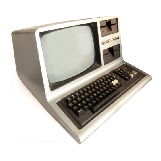
Radio Shack TRS-80 Model III Service Manual
Hide thumbs
Also See for TRS-80 Model III
:
Operation and reference manual
(274 pages)
,
Owner's manual
(163 pages)
,
Service manual
(134 pages)
1
2
3
4
5
6
7
8
9
10
11
12
13
14
15
16
17
18
19
20
21
22
23
24
25
26
27
28
29
30
31
32
33
34
35
36
37
38
39
40
41
42
43
44
45
46
47
48
49
50
51
52
53
54
55
56
57
58
59
60
61
62
63
64
65
66
67
68
69
70
71
72
73
74
75
76
77
78
79
80
81
82
83
84
85
86
87
88
89
90
91
92
93
94
95
96
97
98
99
100
101
102
103
104
105
106
107
108
109
110
111
112
113
114
115
116
117
118
119
120
121
122
123
124
125
126
127
128
129
130
131
132
133
134
Table Of Contents
135
page
of
135
Go
/
135
Contents
Table of Contents
Troubleshooting
Bookmarks
Table of Contents
Table of Contents
List of Illustrations
List of Tables
Introduction
System Overview
TRS-80 Model III Block Diagram
Disassembly/Reassembly
Disassembly
Case
CPU Board
FDC Board
Video Monitor (CRT) and Video Board
Reassembly
RS-232 Board
Main Power Supply
Disk Drive
CPU Circuit Board
Technical Description
Video SYNC Circuits
Processor
Ram
Address Decoding
Memory Map of Model III
IO Port Description
Video
Video Timing Diagram
Keyboard
Cassette Interface
Adjustments and Jumper Positions
Line Printer and Real Time Clock
IO Bus
Model III IO Bus
Input or Output Cycles
Input or Output Cycles with Wait States
IO Bus Timing Diagrams
Model III Port Bits
CPU Printed Circuit Board - Component Side
CPU Printed Circuit Board - Circuit Side
CPU Module Parts List
Model III CPU Schematic Diagram - Video and Horizontal Sync Circuits
Model III CPU Schematic Diagram - Processor Section
Model III CPU Schematic Diagram - RAM Section
Model III CPU Schematic Diagram - Address Decoding Section
Model III CPU Schematic Diagram - Video Section
Model III CPU Schematic Diagram - Keyboard Section
Model III CPU Schematic Diagram - Cassette Interface Section
Model III CPU Schematic Diagram - Line Printer and Real Time Clock Section
Model III CPU Schematic Diagram - I/O Bus Section
Model III CPU Schematic Diagram - RS-232-C Interface and FDC Interface Connectors
Floppy Disk Interface
Control and Data Buffering
Nonmaskable Interrupt Logic
Drive Select Latch and Motor on Logic
Wait State Generation and Waitimout Logic
Clock Generation Logic
Disk Bus Selector Logic
Write Recompensation and Clock Recovery Logic
Adjustments and Jumper Options
Floppy Disk Controller Chip
Jumper Connections
FDC Board to CPU Board Signal Description
Floppy Disk Interface PC Board - Component Side
Floppy Disk Interface PC Board - Circuit Side
Floppy Disk Interface PC Board Parts List
Model III Floppy Disk Interface Schematic
RS-232C Circuit Board
RS-232C Technical Description
BRG Programming Table
Port and Bit Assignments
Port E8H
Port E9H
Port EAH
Port EBH
Port EAH Output Bits with Uart Control Register Disabled
Port EAH Input Bits
RS-232 Board to CPU Board Signal Description
RS-232C PC Board - Component Side
RS-232C PC Board - Circuit Side
RS-232C PC Board Parts List
Model III RS-232C Schematic Diagram
Power Supply
Functional Specifications
Troubleshooting
Equipment for Test Set-Up
Visual Inspection
No Output
Start-Up
Load Board Values
O2 Collector Waveform
Performance Test
Voltage and Ripple Specification
Power Supply Component Values
Power Supply Schematic Diagram
Video Monitor
Video Monitor Printed Circuit Board
Service Adjustments
Deflection Yoke Assembly
Video Monitor Assembly Schematic Diagram
Illustrated Parts Catalog
Outer Case Assembly
Case Top Assembly
Base Plate Assembly
Metal Chassis Assembly
Disk Drive Assembly
Illustrated Parts Catalog Parts List
Miscellaneous
Mini Disk Drive
General Description
Physical Description
Functional Description
Interface Connections
Physical Checkout
PC Board Component Locations
Logic Board (Component Side)
Non-Linear Servo Board (Component Side)
Linear Servo Board (Component Side)
Mounting the Disk Drive
Flat Ribbon Cable Assembly
Resistor Terminator
Cable Assembly - Connector Pin Removal Chart
Theory of Operation
Functional Block Diagram Description
Index
Spindle Drive
Data Electronics
Functional Block Diagram
FM Recording
Data Recording
Data Reproduction
Write Timing Diagram
Read Timing Diagram
Operation
Select Lines (DS1-DS4)
Direction and Step (DIR) (STEP)
Compensated Write Data (CWD)
Interface Connector PIN Assignments, J1 (External), J4 (Internal)
Power Connector PIN Assignment
Side Select (SDSEL)
Index Pulse (IP)
Write Protect (WPRT)
Read Data (RD)
Maintenance
Physical Description of the PC Boards
Circuit Board Test Points
Option Select
Logic Board Test Points and Connector Locations
Servo Board Connector Locations
Preventive Maintenance
Cleaning the Head
Alignment and Adjustment
Drive Motor Maintenance
Head Radial Alignment/Ce Alignment
"Cat Eyes" Pattern
Radial Adjustment
Track Alignment
Index Sector Adjustment
Track Stop Adjustment
Index Adjustment
Head Amplitude/Compliance Check
Final Check
Upper Arm and Carriage
Disk Controller Board Parts List
Servo (Motor Control) Board Parts List
Illustrated Parts Catalog - Exploded View
Mini-Disk Drive Schematic
Non-Linear Servo Board
Linear Servo Board
Mini-Disk Drive Schematic of New Board
Advertisement
Quick Links
1
Cpu Board
2
Video Monitor (Crt) and Video Board
Download this manual
See also:
Owner's Manual
,
Operating Manual
Table of
Contents
Previous
Page
Next
Page
1
2
3
4
5
Advertisement
Table of Contents
Related Manuals for Radio Shack TRS-80 Model III
Desktop Radio Shack TRS-80 Model 3 Operation And Reference Manual
Operation and reference manual (276 pages)
Desktop Radio Shack TRS-80 Model III Operation And Reference Manual
(274 pages)
Desktop Radio Shack TRS-80 model III Owner's Manual
Mini-disk operation, trsdos disk operating system, disk basic programming language (163 pages)
Desktop Radio Shack TRS-80 III Service Manual
Microcomputer (134 pages)
Desktop Radio Shack 26-1061 Service Manual
(132 pages)
Desktop Radio Shack TRS-80 Service Manual
Microcomputer (132 pages)
Desktop Radio Shack TRS-80 Model III Operation Manual
(30 pages)
Desktop Radio Shack TRS-80 III Service Manual
Modification kit, first internal disk drive (7 pages)
Desktop Radio Shack TRS-80 Service Manual
Micro color computer (44 pages)
Desktop Radio Shack TRS-80 Preliminary User's Manual
Micro computer system (30 pages)
Desktop Radio Shack TRS-80 Service Manual
Microcomputer (199 pages)
Desktop Radio Shack TRS-80 Model II Reference Manual
Disk operating system (274 pages)
Desktop Radio Shack TRS-80 II Technical Reference Manual
(190 pages)
Desktop Radio Shack ART GALLERY TRS-80 Manual
Color computer (32 pages)
Desktop Radio Shack TRS-80 Model 100 Basic Manual
Basic language lab (210 pages)
Desktop Radio Shack TRS-80 DT-1 Owner's Manual
(68 pages)
Related Products for Radio Shack TRS-80 Model III
Radio Shack TRS-80 PC-4
Radio Shack TRS-80 Model 4
Radio Shack TRS-80 VIDEOTEX
Radio Shack TRS-80 Color Computer 2
Radio Shack TRS-80 Model 16
Radio Shack TRS-80 Model 3
Radio Shack TRS-80 4P Gate Array
Radio Shack TRS-80 Model 16B
Radio Shack TRS-80 DT-1
Radio Shack TRS-80 MC-10
Radio Shack Tandy 1000
Radio Shack TRS-80 X-PAD GT-116
Radio Shack TRS-80 CR-510
Radio Shack TRS-80 26-3503
Radio Shack TRS-80 26-3501
Radio Shack TRS-80 PT-210
Table of Contents
Print
Rename the bookmark
Delete bookmark?
Delete from my manuals?
Login
Sign In
OR
Sign in with Facebook
Sign in with Google
Upload manual
Upload from disk
Upload from URL