Table of Contents
Troubleshooting

Related Manuals for U-Line 3090WCWC


Summary of Contents for U-Line 3090WCWC
- Page 1 USER GUIDE SAFETY • INSTALLATION & INTEGRATION • OPERATING INSTRUCTIONS • MAINTENANCE • SERVICE RIGHT PRODUCT. RIGHT PLACE. RIGHT TEMPERATURE. SINCE 1962. Modular 3000 Series 3090WCWC 90 cm Wine Cellar Model • •...
-
Page 2: Table Of Contents
Troubleshooting Extended Grille / Plinth Installation Control Quick Guide Door Swing Thermistor Door Stop Defrost Door Adjust Remove Fan and Cover Operating Instructions First Use Control Operation Sabbath Mode Airflow and Product Loading U-Line Wine Guide Recommended Wine Storage Maintenance... - Page 3 1. U-Line Customer Care must be contacted immediately at +1.800.779.2547. 2. Service or repairs performed on the unit without prior written approval from U-Line is not permitted. If the unit has been altered or repaired in the field without prior written approval from U-Line, claims will not be eligible.
-
Page 4: Safety And Warning
USER GUIDE u-line.com SAFETY • INSTALLATION & INTEGRATION • OPERATING INSTRUCTIONS • MAINTENANCE • SERVICE Safety and Warning This appliance is not intended for use by persons (including children) with reduced physical, sensory or mental capabilities, or lack of experience or knowledge,... - Page 5 Allow unit temperature to stabilize for 24 hours before use. Do not block any internal fans. Use only genuine U-Line replacement parts. Imitation parts can damage the unit, affect its operation or performance and may void the warranty.
-
Page 6: Disposal And Recycling
USER GUIDE u-line.com SAFETY • INSTALLATION & INTEGRATION • OPERATING INSTRUCTIONS • MAINTENANCE • SERVICE Disposal and Recycling DANGER RISK OF CHILD ENTRAPMENT. Before you throw away your old refrigerator or freezer, take off the doors and leave shelves in place so children may not easily climb inside. -
Page 7: Environmental Requirements
USER GUIDE u-line.com SAFETY • INSTALLATION & INTEGRATION • OPERATING INSTRUCTIONS • MAINTENANCE • SERVICE Environmental Requirements This model is intended for indoor/interior applications only and is not to be used in installations that are open/ exposed to natural elements. - Page 8 USER GUIDE u-line.com SAFETY • INSTALLATION & INTEGRATION • OPERATING INSTRUCTIONS • MAINTENANCE • SERVICE Electrical NOTICE Electrical installation must observe all state and WARNING local codes. This unit requires connection to a grounded (three-prong), polarized receptacle SHOCK HAZARD — Electrical Grounding that has been placed by a qualified electrician.
-
Page 9: Cutout Dimensions
SAFETY • INSTALLATION & INTEGRATION • OPERATING INSTRUCTIONS • MAINTENANCE • SERVICE Cutout Dimensions CUTOUT DIMENSIONS PREPARE SITE Your U-Line product has been designed exclusively for a built-in installation. When built-in, your unit does not require additional air space for top, sides, or rear. Preferred location... -
Page 10: Product Dimensions
USER GUIDE u-line.com SAFETY • INSTALLATION & INTEGRATION • OPERATING INSTRUCTIONS • MAINTENANCE • SERVICE Product Dimensions 23-7/16" (590 mm)* 33-11/16" to 34-11/16" (856 mm to 881 mm) 35-7/16" (900 mm) 3-5/8" to 4-5/8" (92 to 118 mm) *Includes 3/4" (20 mm) integrated panel... -
Page 11: Side By Side Installation
USER GUIDE u-line.com SAFETY • INSTALLATION & INTEGRATION • OPERATING INSTRUCTIONS • MAINTENANCE • SERVICE Side-by-Side Installation Hinge-by-Hinge Installation (Mullion) When installing two units hinge-by-hinge, 13/16" (22 mm) OTHER SITE REQUIREMENTS is required for integrated models. Additional space may be Side-by-Side Installation needed for any knobs, pulls or handles installed. -
Page 12: Anti-Tip Bracket
USER GUIDE u-line.com SAFETY • INSTALLATION & INTEGRATION • OPERATING INSTRUCTIONS • MAINTENANCE • SERVICE Anti-Tip Bracket SIDE MOUNT Left Hinged Cabinet Right Hinged Cabinet CAUTION The anti-tip bracket must be installed to prevent the unit from tipping when doors are fully opened or excess weight is placed on the front of the unit. -
Page 13: General Installation
USER GUIDE u-line.com SAFETY • INSTALLATION & INTEGRATION • OPERATING INSTRUCTIONS • MAINTENANCE • SERVICE General Installation INSTALLATION 1. Plug in the power/electrical cord. 1. Use a level to confirm the unit is level. Level 2. Gently push the unit into position. Be careful not to should be placed along entangle the cord. -
Page 14: Integrated Panel Dimensions
USER GUIDE u-line.com SAFETY • INSTALLATION & INTEGRATION • OPERATING INSTRUCTIONS • MAINTENANCE • SERVICE Integrated Panel Dimensions Integrated Frame Dimensions INTEGRATED FRAME BACK SURFACE MUST HAVE AMPLE FLAT SURFACE 3/4" TO MOUNT OVERLAY FRAME FLAT AND WITHOUT INTERFERENCE (20 mm) NOTICE 17-1/2"... - Page 15 3-1/2" (89 mm) NOTE: Many cabinet manufacturers provide a ready solution for a handleless, integrated design that can be easily applied to your U-Line 3000 Series model. Consult Wooden Insert your cabinet manufacturer for applicable design and installation details. The cabinet manufacturer’s solution to...
- Page 16 USER GUIDE u-line.com SAFETY • INSTALLATION & INTEGRATION • OPERATING INSTRUCTIONS • MAINTENANCE • SERVICE Handleless Integrated Frame Dimensions 1/8" (3 mm) Top Design 1/4" (6 mm) 7/8" (22 mm) Ref. R 5/8" 2-3/8" (R 16 mm) (60 mm) 17-1/2"...
- Page 17 USER GUIDE u-line.com SAFETY • INSTALLATION & INTEGRATION • OPERATING INSTRUCTIONS • MAINTENANCE • SERVICE EXTENDED INTEGRATED FRAME NOTICE Due to differences in surrounding cabinetry the panel may not perfectly align with door. The procedure below is designed to provide a finished panel that seamlessly integrates with surrounding cabinetry.
- Page 18 USER GUIDE u-line.com SAFETY • INSTALLATION & INTEGRATION • OPERATING INSTRUCTIONS • MAINTENANCE • SERVICE Integrated Panel/Integrated Frame Integrated Panel U-Line U-Line Cabinet Unit Unit 3-5/16" (89 mm) 3-5/16" (89 mm) > 3-5/16" (> 89 mm) 4-5/16" (114 mm) 4-5/16" (114 mm)
- Page 19 USER GUIDE u-line.com SAFETY • INSTALLATION & INTEGRATION • OPERATING INSTRUCTIONS • MAINTENANCE • SERVICE Extended Integrated Frame Dimensions BACK SURFACE MUST HAVE AMPLE FLAT SURFACE 3/4" TO MOUNT INTEGRATED FRAME FLAT AND WITHOUT INTERFERENCE (20 mm) 17-1/2" (445 mm) 2-3/4"...
-
Page 20: Integrated Grille / Plinth Dimensions
3. Apply double sided tape to the backside of the integrated grill (plinth strip/base fascia). Use the diagram below for reference. U-Line recommends ™ ™ tape, a high strength bonding tape. -
Page 21: Integrated Panel Installation
6. Secure integrated panel to door using Clamp 1. Fully open door. clamps. A robust tape may also be used. U-Line 2. Starting at corner, pull recommends the gasket away from door. use of bar clamps Door/Drawer to secure the panel 3. - Page 22 USER GUIDE u-line.com SAFETY • INSTALLATION & INTEGRATION • OPERATING INSTRUCTIONS • MAINTENANCE • SERVICE 11.Remove clamps from door. NOTICE If panel requires additional adjustment after removing clamps, slightly loosen each screw and adjust panel as necessary. Tighten screws upon completion.
-
Page 23: Grille / Plinth Installation
USER GUIDE u-line.com SAFETY • INSTALLATION & INTEGRATION • OPERATING INSTRUCTIONS • MAINTENANCE • SERVICE Grille - Plinth Installation Installing the grille (plinth strip/base fascia) REMOVING AND INSTALLING GRILLE 1. Align slots in grille (plinth strip/base fascia) rail with (PLINTH STRIP/BASE FASCIA) -
Page 24: Door Swing
USER GUIDE u-line.com SAFETY • INSTALLATION & INTEGRATION • OPERATING INSTRUCTIONS • MAINTENANCE • SERVICE Door Swing For models that are installed adjacent to a wall, 1/4" (6 mm) clearance is recommended from wall on hinge side to allow the door to open 90°. Allow for additional space for any knobs or pulls installed on the integrated panel/ frame. -
Page 25: Door Stop
3. Once cover is removed, slide hinge pin into hole as shown. Pin should slide into place, stopping the door at Your U-Line unit was shipped to you with the optional 90° 90°; if the pin does not go into the hole shown, hold pin. -
Page 26: Door Adjust
USER GUIDE u-line.com SAFETY • INSTALLATION & INTEGRATION • OPERATING INSTRUCTIONS • MAINTENANCE • SERVICE Door Adjustments DOOR ALIGNMENT AND ADJUSTMENT Align and adjust the door if it is not level or is not sealing properly. If the door is not sealed, the unit may not cool... - Page 27 USER GUIDE u-line.com SAFETY • INSTALLATION & INTEGRATION • OPERATING INSTRUCTIONS • MAINTENANCE • SERVICE 3. Using T-25 Torx bit loosen screw #1 and remove screw #2 on top and bottom hinge. Slide and remove the door from unit. Completely remove screw #1 on top and bottom.
-
Page 28: First Use
USER GUIDE u-line.com SAFETY • INSTALLATION & INTEGRATION • OPERATING INSTRUCTIONS • MAINTENANCE • SERVICE First Use All U-Line controls are preset at the factory. Initial startup requires no adjustments. NOTICE U-Line recommends allowing the unit to run overnight before loading with product. -
Page 29: Control Operation
USER GUIDE u-line.com SAFETY • INSTALLATION & INTEGRATION • OPERATING INSTRUCTIONS • MAINTENANCE • SERVICE Control Operation Your unit is equipped with two zones. Each zone can be set to a different mode. Zone Indicator Zone Toggle Zone Indicator Select... -
Page 30: Adjusting Temperature Settings
USER GUIDE u-line.com SAFETY • INSTALLATION & INTEGRATION • OPERATING INSTRUCTIONS • MAINTENANCE • SERVICE ® U-SELECT CONTROL Mode Settings Chart Digital Display Setting Default °F (°C) Range °F (°C) Red Wine 55 (12) 55 - 65 (12 - 18) - Page 31 INTERIOR LIGHTING cooled to a point below optimum or frozen. Your U-Line 3000 Series unit uses a state of the art LED lighting system. The 3036 model dual zone’s lighting can The following chart lists modes which include the quick be independently controlled or set as a group.
- Page 32 ERROR NOTIFICATION CUSTOMER MENU The 3000 model series continuously monitors a series of The 3000 Series of U-Line undercounter refrigeration inputs and parameters to ensure proper and efficient appliances contains a feature rich customer menu. The operation of your unit. Should the system detect a fault,...
- Page 33 ENGLISH 3. To return to the Customer Menu, press and select “Return to Menu”. Down The U-Line 3000 Series of models supports a number of display languages including English, Spanish, French and Energy Saver Mode German. Energy Saver Mode Select Indicator 1.
- Page 34 USER GUIDE u-line.com SAFETY • INSTALLATION & INTEGRATION • OPERATING INSTRUCTIONS • MAINTENANCE • SERVICE Sound Level 2. Press . The selection will begin to flash. Select 3. Press to select between °F (Fahrenheit) or °C RETURN TO MENU (Celsius).
- Page 35 To access the Help Menu, select Help from the Customer Menu. Press to scroll through available information. The Help screen displays the following: • Model. • U-Line contact information. • Software version. • Serial Number. To exit the Help menu, press to select “Return to Menu”...
-
Page 36: Sabbath Mode
USER GUIDE u-line.com SAFETY • INSTALLATION & INTEGRATION • OPERATING INSTRUCTIONS • MAINTENANCE • SERVICE 7. Press to change “Off” to “On”. Sabbath Mode 8. Press to confirm your selection. The Display will fade out as the unit enters Sabbath Mode. -
Page 37: Airflow And Product Loading
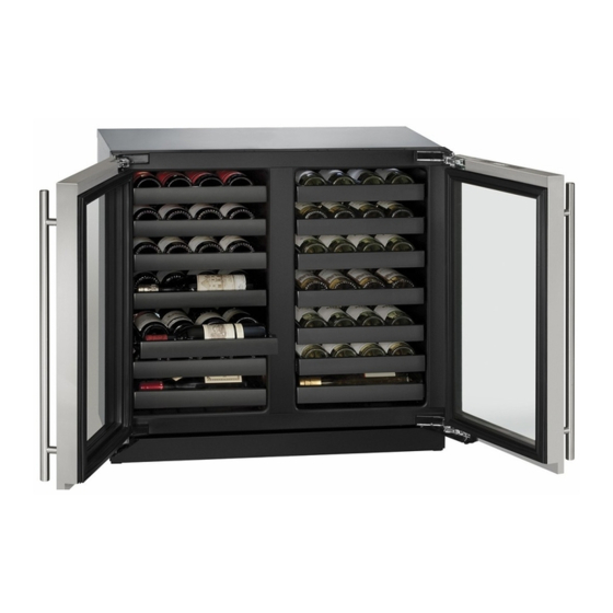
Do not install the unit behind a door. When properly loaded, your U-Line unit will store up to 62 (750 ml) bottles of wine. Door Removed For Illustration Purposes Airflow and Product Loading 1... -
Page 38: U-Line Wine Guide
YOUNG wine OLD wine LIGHT-BODIED wine FULL-BODIED wine Any step back in quality will be noticed. If a fine wine is tasted prior to a lesser wine, many of the fine wine’s subtle qualities may be missed. U-Line Wine Guide 1... - Page 39 Great Bordeaux’s may have as much as a 10-year plateau before fading. Myth 4: Wine color does not change with aging. Truth: As red wines age they get lighter in color while whites get darker. U-Line Wine Guide 2...
- Page 40 Wines can become flat or tired when voids and vacuums are created inside the wine bottle. In order to create voids and vacuums within a liquid, aggressive motion or shaking of the wine bottle would have to occur. U-Line Wine Guide 3...
- Page 41 Approximately 45°F (7°C) Sparkling ® Wine Captain Models - A Touch of Elegance In 1985 U-Line was the first North American appliance manufacturer to develop a residential wine storage unit, ® ® the Wine Captain . Each U-Line Wine Captain...
-
Page 42: Recommended Wine Storage
Specially designed horizontal wine racks properly position the bottles so the wine remains in contact with the cork, which ensures the cork does not become dry. U-Line recommends arranging wine bottles as shown in the illustrations below. Racks 1 through 5: Larger diameter bottles may be stored on the shaded racks, illustrated below. -
Page 43: Cleaning
® monthly. For best results use Claire Stainless Steel Polish and Cleaner, which can be purchased from U-Line Rinse the interior using a soft sponge and clean water. Corporation (Part Number 173348). Comparable products are acceptable. Frequent cleaning will remove surface contamination that could lead to rust. - Page 44 USER GUIDE u-line.com SAFETY • INSTALLATION & INTEGRATION • OPERATING INSTRUCTIONS • • SERVICE MAINTENANCE NOTICE The drain pan was not designed to capture the water created when manually defrosting. To prevent water from overflowing the drain pan and possibly damaging water sensitive flooring, the unit must be removed from cabinetry.
-
Page 45: Cleaning Condenser
USER GUIDE u-line.com SAFETY • INSTALLATION & INTEGRATION • OPERATING INSTRUCTIONS • MAINTENANCE • SERVICE Cleaning Condenser INTERVAL - EVERY SIX MONTHS To maintain operational efficiency, keep the front grille (plinth strip/base fascia) free of dust and lint, and clean the condenser when necessary. -
Page 46: Wine Rack Installation
USER GUIDE u-line.com SAFETY • INSTALLATION & INTEGRATION • OPERATING INSTRUCTIONS • MAINTENANCE • SERVICE Wine Rack Installation To insert wine racks in the cabinet: 1. Align the left and right rack channels with the tracks in To remove wine racks for cleaning: the cabinet. -
Page 47: Extended Non-Use
If the unit will be exposed to temperatures of 40°F (5°C) or less, the steps above must be followed. For questions regarding winterization, please call U-Line at +1.800.779.2547. CAUTION Damage caused by freezing temperatures is not covered by the warranty. -
Page 48: Troubleshooting
• Compressor: The compressor makes a hum or pulsing sound that may be heard when it operates. BEFORE CALLING FOR SERVICE If you think your U-Line product is malfunctioning, read • Evaporator: Refrigerant flowing through an evaporator the CONTROL OPERATION section to clearly understand may sound like boiling liquid. - Page 49 12H+ temperature +10° and sealing. Contact properly. For other error codes contact over set point for Customer Care if U-Line Customer Service. over 12 hours. persistent. Product Is Because product in contact with the rear wall (L) (R) Temp Lo...
- Page 50 USER GUIDE u-line.com SAFETY • INSTALLATION & INTEGRATION • OPERATING INSTRUCTIONS • MAINTENANCE • SERVICE 6. After 24 hours, check the temperature of the water. If required, adjust the temperature control in a small increment (see CONTROL OPERATION). Causes which affect the internal temperatures of the cabinet include: •...
-
Page 51: Warranty
2. During the two year warranty period for all U-Line covered under the terms of this warranty as a result of products, U-Line shall be responsible for the labor that exposure. - Page 52 USER GUIDE u-line.com SAFETY • INSTALLATION & INTEGRATION • OPERATING INSTRUCTIONS • MAINTENANCE • SERVICE installation of the product or from any other cause whatsoever, whether based on warranty (express or implied) or otherwise based on contract, tort, or any other theory of liability.
-
Page 53: Wire Diagram
USER GUIDE u-line.com SAFETY • INSTALLATION & INTEGRATION • OPERATING INSTRUCTIONS • MAINTENANCE • SERVICE Wire Diagram Wire Diagram 1... -
Page 54: Product Liability
U-Line in an unaltered condition. The dealer would then be authorized to • When the unit is ready for pickup, contact U-Line at permanently replace the end-user’s product at no cost to +1.800.779.2547 and U-Line will make arrangements the end-user. -
Page 55: Warranty Claims
USER GUIDE u-line.com SAFETY • INSTALLATION & INTEGRATION • OPERATING INSTRUCTIONS • MAINTENANCE • SERVICE Warranty Claims warranty status. We also accept the following information to verify warranty status: The following information defines the parameters for filing a warranty claim: •... -
Page 56: Ordering Replacement Parts
Warranty parts will be shipped at no charge after U-Line confirms warranty status. Please provide the model, serial number, part number and part description. Some parts will require color or voltage information. -
Page 57: System Diagnosis Guide
USER GUIDE u-line.com SAFETY • INSTALLATION & INTEGRATION • OPERATING INSTRUCTIONS • MAINTENANCE • SERVICE System Diagnosis Guide REFRIGERATION SYSTEM DIAGNOSIS GUIDE System Suction Suction Compressor Condenser Capillary Evaporator Wattage Condition Pressure Line Discharge Tube Normal Normal Slightly below Very hot... -
Page 58: Compressor Specifications
USER GUIDE u-line.com SAFETY • INSTALLATION & INTEGRATION • OPERATING INSTRUCTIONS • MAINTENANCE • SERVICE Compressor Specifications OVERLOAD PROTECTOR STARTING RELAY DANGER Electrocution can cause death or serious injury. Burns from hot or cold surfaces can cause RELAY COVER CAPACITOR serious injury. -
Page 59: Troubleshooting Extended
DC outputs located on the relay/power board. Included in this section is some diagnostic tips and as always, if additional help is required please contact the U-Line Corp, “Customer Care Facility” at +1.800.779.2547 for assistance. CAUTION Never attempt to repair or perform maintenance on the unit until the main electrical power has been disconnected from the unit. - Page 60 USER GUIDE u-line.com SAFETY • INSTALLATION & INTEGRATION • OPERATING INSTRUCTIONS • MAINTENANCE • SERVICE TROUBLESHOOTING GUIDE Concern Potential Causes Suggested Remedy Not Cooling Compressor overheating Verify proper air flow through condenser (Refer to Airflow/General Information Section). Confirm condenser fan operation (Refer to Airflow/General Information Section).
- Page 61 USER GUIDE u-line.com SAFETY • INSTALLATION & INTEGRATION • OPERATING INSTRUCTIONS • MAINTENANCE • SERVICE MAIN CONTROL Testing The Main Control If the main control is suspected of being faulty, the The main control board is very robust and is rarely the following procedure should be performed to verify main cause of system issues.
- Page 62 USER GUIDE u-line.com SAFETY • INSTALLATION & INTEGRATION • OPERATING INSTRUCTIONS • MAINTENANCE • SERVICE Other Suspected Main Control Faults CONVECTION COOLING If other components have been ruled out as being faulty All 3000 series units are equipped with an advanced but the unit continues to have operating issues, it is most convection cooling system.
- Page 63 USER GUIDE u-line.com SAFETY • INSTALLATION & INTEGRATION • OPERATING INSTRUCTIONS • MAINTENANCE • SERVICE FAULT SYSTEM DIAGNOSIS GUIDE Error Solution 1 Solution 2 Solution 3 No Comm Inspect Customer UI and Data Cable (if defective replace entire door) Zone T Open...
- Page 64 USER GUIDE u-line.com SAFETY • INSTALLATION & INTEGRATION • OPERATING INSTRUCTIONS • MAINTENANCE • SERVICE THERMISTORS REED SWITCH Thermistors are used for various temperature readings. A reed switch is used to monitor door state. When the Thermistors provide reliable temperature readings using a...
- Page 65 USER GUIDE u-line.com SAFETY • INSTALLATION & INTEGRATION • OPERATING INSTRUCTIONS • MAINTENANCE • SERVICE Control Operation - Service TO ENTER THE MAIN SERVICE MENU TO GO TO NEXT SUB-MENU ITEM YOU MUST ARROW UP TO “RETURN TO MENU” PRESS AND HOLD...
- Page 66 USER GUIDE u-line.com SAFETY • INSTALLATION & INTEGRATION • OPERATING INSTRUCTIONS • MAINTENANCE • SERVICE SERVICE MENU The All Errors option keeps record of any system errors. When an error occurs it is recorded to all errors. The In addition to a feature rich customer menu, the 3000...
- Page 67 USER GUIDE u-line.com SAFETY • INSTALLATION & INTEGRATION • OPERATING INSTRUCTIONS • MAINTENANCE • SERVICE Description Solution Description Solution L Zone T Left Zone thermistor Check thermistor R Temp Right Zone Is condenser coil clean? Is Short circuit shorted. connection to harness for Hi 12H+ temperature +10°F...
- Page 68 USER GUIDE u-line.com SAFETY • INSTALLATION & INTEGRATION • OPERATING INSTRUCTIONS • MAINTENANCE • SERVICE To exit the Actual Temps menu, press to select Relay Toggle “Return to Menu” and press to confirm. Select Relay Status RETURN TO MENU RELAY TOGGLE...
- Page 69 USER GUIDE u-line.com SAFETY • INSTALLATION & INTEGRATION • OPERATING INSTRUCTIONS • MAINTENANCE • SERVICE To exit the Relay Toggle menu, Press to select “Return Outputs to Menu” and press to confirm. Select Input Status RETURN TO MENU OUTPUTS EVAP FAN=0%...
- Page 70 USER GUIDE u-line.com SAFETY • INSTALLATION & INTEGRATION • OPERATING INSTRUCTIONS • MAINTENANCE • SERVICE Offsets Self Test Select Select RETURN TO MENU RETURN TO MENU OFFSETS SELF TEST ZONE = 1°F NO ERRORS EVAP = 1°F try “RELAY TOGGLE”...
- Page 71 USER GUIDE u-line.com SAFETY • INSTALLATION & INTEGRATION • OPERATING INSTRUCTIONS • MAINTENANCE • SERVICE NOTE: Air temperature does not reflect product To change set point temperatures. 4. Press , the selected set point will begin to flash. Differential Cycle Start °F (°C) Cycle End °F (°C)
- Page 72 The Fan Delay menu option allows the modification of fan NOTICE run times during and after a cooling cycle. In order to Before altering model selection U-Line customer allow time for the evaporator to properly cool, the service must be notified. Failure to notify...
- Page 73 USER GUIDE u-line.com SAFETY • INSTALLATION & INTEGRATION • OPERATING INSTRUCTIONS • MAINTENANCE • SERVICE To exit Fan Delay, press to select “Return to Menu” and press to confirm. Showroom Mode Select RETURN TO MENU SHOWROOM MODE Down Showroom displays a number of features and allows the unit to be powered on without running the cooling system.
-
Page 74: Thermistor 1
USER GUIDE u-line.com SAFETY • INSTALLATION & INTEGRATION • OPERATING INSTRUCTIONS • MAINTENANCE • SERVICE Thermistors Thermistor three is located along the right hand side wall in the right zone. It is used to maintain the operating Thermistors are used for various temperature readings. - Page 75 USER GUIDE u-line.com SAFETY • INSTALLATION & INTEGRATION • OPERATING INSTRUCTIONS • MAINTENANCE • SERVICE Nominal Resistance Temp (F) Temp (C) (OHMS)* 12696 9951 7855 6246 5000 4029 3266 2665 2186 1803 1495 1247 1044 * (=/-5%) Thermistor 2...
-
Page 76: Defrost
USER GUIDE u-line.com SAFETY • INSTALLATION & INTEGRATION • OPERATING INSTRUCTIONS • MAINTENANCE • SERVICE Defrost These units are manual defrost. To defrost unit remove ice bucket. Turn unit off. Use toweling inside to absorb water as it melts down. This will help prevent water from getting onto customer’s floor. -
Page 77: Remove Fan And Cover
USER GUIDE u-line.com SAFETY • INSTALLATION & INTEGRATION • OPERATING INSTRUCTIONS • MAINTENANCE • SERVICE Remove Fan and Cover 3. Disconnect power to the unit. CONVECTION COOLING 4. Remove rear center cover from unit. This unit is equipped with an advanced convection cooling system. - Page 78 USER GUIDE u-line.com SAFETY • INSTALLATION & INTEGRATION • OPERATING INSTRUCTIONS • MAINTENANCE • SERVICE 10.Remove two evaporator cover screws from top of 15.Installation is the reverse of removal. evaporator cover to be removed. 16.Care must be taken to assure that the bottom of the evaporator cover gets reinstalled behind the front edge of the drain trough.