Table of Contents
Advertisement
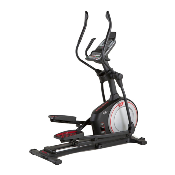
Model No. NTEVEL99915.0
Serial No.
USER'S MANUAL
Write the serial number in the space
above for reference.
Serial Number
Decal
CUSTOMER SERVICE
UNITED KINGDOM
Call: 0330 123 1045
From Ireland: 053 92 36102
Website: www.iconsupport.eu
E-mail: csuk@iconeurope.com
Write:
ICON Health & Fitness, Ltd.
Unit 1D, The Gateway
Fryers Way, Silkwood Park
OSSETT
WF5 9TJ
UNITED KINGDOM
AUSTRALIA
Call: 1800 993 770
E-mail: australiacc@iconfitness.com
Write:
ICON Health & Fitness
PO Box 635
WINSTON HILLS NSW 2153
AUSTRALIA
CAUTION
Read all precautions and instruc-
tions in this manual before using
this equipment. Keep this manual
www.iconeurope.com
for future reference.
Advertisement
Table of Contents

Related Manuals for NordicTrack Elite 11.0 NTEVEL99915.0


Summary of Contents for NordicTrack Elite 11.0 NTEVEL99915.0
- Page 1 Model No. NTEVEL99915.0 Serial No. USER’S MANUAL Write the serial number in the space above for reference. Serial Number Decal CUSTOMER SERVICE UNITED KINGDOM Call: 0330 123 1045 From Ireland: 053 92 36102 Website: www.iconsupport.eu E-mail: csuk@iconeurope.com Write: ICON Health & Fitness, Ltd. Unit 1D, The Gateway Fryers Way, Silkwood Park OSSETT...
-
Page 2: Table Of Contents
® Bluetooth SIG, Inc. and are used under license. Google Maps is a trademark of Google Inc. IFIT is a registered trademark of ICON Health & Fitness, Inc NORDICTRACK is a registered trademark of ICON Health & Fitness, Inc. -
Page 3: Important Precautions
IMPORTANT PRECAUTIONS WARNING: To reduce the risk of burns, fire, electric shock, or injury to persons, read all important precautions and instructions in this manual and all warnings on your elliptical before using your elliptical. ICON assumes no responsibility for personal injury or property damage sus- tained by or through the use of this product. -
Page 4: Before You Begin
BEFORE YOU BEGIN Thank you for selecting the revolutionary reading this manual, please see the front cover of this NORDICTRACK ELITE 11.0 elliptical. The ELITE 11.0 manual. To help us assist you, note the product model ® elliptical provides an impressive selection of features number and serial number before contacting us. -
Page 5: Part Identification Chart
PART IDENTIFICATION CHART Use the drawings below to identify the small parts needed for assembly. The number in parentheses below each drawing is the key number of the part, from the PART LIST near the end of this manual. The number following the key number is the quantity needed for assembly. -
Page 6: Assembly
ASSEMBLY • Assembly requires two persons. • In addition to the included tool(s), assembly requires the following tools: • Place all parts in a cleared area and remove the one Phillips screwdriver packing materials. Do not dispose of the packing materials until you finish all assembly steps. - Page 7 3. Press the Cover Mounts (106) on the underside of the Rear Stabilizer Cover (15) into the Rear Stabilizer (2). 4. With the help of a second person, place some of the packing materials (not shown) under the front of the Frame (1). Have the second per- son hold the Frame to prevent it from tipping while you complete this step.
- Page 8 5. Orient the Upright (4) as shown. Have a second person hold the Upright near the Frame (1). Wire See the inset drawing. Locate the wire tie in the lower end of the Upright (4). Tie the wire tie to the Main Wire (110).
- Page 9 7. Using a plastic bag to keep your fingers clean, apply some of the included grease to the Pivot Axle (35) and to two 16mm Wave Washers (54). Insert the Pivot Axle (35) through the Upright (4) and center it. Tip: It may be helpful to use a rubber mallet.
-
Page 10: Tip: Avoid Pinching The Wires. Attach The
9. Untie and discard the wire tie on the Main Wire (110). While a second person holds the Console (7) near the Upright (4), connect the wires on the Console to the Main Wire (110) and to the Sensor Wires (63). Insert the excess wire into the Upright (4). - Page 11 11. Orient the Right Pedal Arm (58) as shown. Apply grease to the axle on the Right Pedal Arm (58). Attach the Right Pedal Arm (58) to the Right Roller Arm (59) with an M8 x 14mm Shoulder Screw (126), a Small Axle Cover (55), and an M8 Washer (97).
- Page 12 13. Orient the Rear Upright Cover (81) as shown. Attach the Rear Upright Cover (81) to the Upright (4) with four M4 x 16mm Screws (101); start all the Screws, and then tighten them. Orient the Front Upright Cover (117) as shown. Attach the Front Upright Cover (117) around the Upright (4) by pressing it onto the Rear Upright Cover (81).
- Page 13 15. Identify the Right Upper Body Leg Inner Cover (83) and orient it as shown. Attach the Right Upper Body Leg Inner Cover (83) to the Right Upper Body Leg (60) with an M4 x 16mm Screw (101) and an M5 Washer (94).
- Page 14 17. Orient the Rear Console Cover (80) as shown. Attach the Rear Console Cover (80) to the Upright (4) with two M4 x 16mm Screws (101). Orient the Front Console Cover (79) as shown. Attach the Front Console Cover (79) around the Upright (4) by pressing it onto the Rear Console Cover (80).
-
Page 15: How To Use The Elliptical
HOW TO USE THE ELLIPTICAL HOW TO PLUG IN THE POWER CORD Follow the steps below to plug in the power cord. This product must be earthed. If it should malfunc- 1. Plug the indicated end of the power cord into the tion or break down, earthing provides a path of least socket on the frame. - Page 16 HOW TO MOVE THE ELLIPTICAL HOW TO LEVEL THE ELLIPTICAL Due to the size and weight of the elliptical, moving If the elliptical it requires two persons. Stand in front of the elliptical, rocks slightly on hold the upright, and place one foot against one of the your floor during wheels.
- Page 17 HOW TO EXERCISE ON THE ELLIPTICAL To mount the elliptical, hold the handlebars or the Upper upper body arms and step onto the pedal that is in the Body Arms lower position. Then, step onto the other pedal. Push the pedals until they begin to move with a continuous motion.
- Page 18 CONSOLE DIAGRAM MAKE YOUR FITNESS GOALS A REALITY WITH IFIT.COM With your new iFit-compatible fitness equipment, you can use an array of features on iFit.com to make your fitness goals a reality: Exercise anywhere in the world with customizable Google Maps. Download training workouts designed to help you reach your personal goals.
- Page 19 FEATURES OF THE CONSOLE Note: If there is a sheet of plastic on the display, remove the plastic. The advanced console offers an array of features designed to make your workouts more effective and Note: The console can display speed and distance in enjoyable.
- Page 20 HOW TO USE THE MANUAL MODE 4. Follow your progress with the display. 1. Begin pedaling or press any button on the The display can show the following workout console to turn on the console. information: See HOW TO TURN ON THE POWER on page 19.
- Page 21 Stride—This display mode will show the total num- Press the Home button to exit the workout and ber of strides you have pedaled. return to the default menu (see HOW TO CHANGE CONSOLE SETTINGS on page 28 to set the Time—When the manual mode is selected, this default menu).
- Page 22 7. When you are finished exercising, unplug the When your pulse is detected, a heart symbol will flash in the display each time your heart beats, power cord. one or two dashes will appear, and then your heart rate will be shown. For the most accurate heart If the pedals do not move for several seconds, a rate reading, hold the contacts for at least 15 tone will sound and the console will pause.
- Page 23 HOW TO USE AN ONBOARD WORKOUT During the workout, 1. Begin pedaling or press any button on the the profiles console to turn on the console. on the speed and Profile See HOW TO TURN ON THE POWER on incline tabs page 19.
- Page 24 5. Measure your heart rate if desired. To stop the workout at any time, press the Pause/ End button or stop pedaling. The time will flash in the display. To resume the workout when the con- See step 5 on page 21. sole is paused, simply resume pedaling.
- Page 25 HOW TO USE A SET-A-GOAL WORKOUT Note: The calorie goal is an estimate of the number of calories that you will burn during 1. Begin pedaling or press any button on the the workout. The actual number of calories that console to turn on the console.
- Page 26 HOW TO USE AN IFIT WORKOUT Press the Map button, the Train button, or the Lose Wt. button to download the next workout of that You must have an iFit module to use an iFit workout. type in your schedule. To purchase an iFit module at any time, go to www.iFit.com or call the telephone number on the Press the Compete button to compete in a race...
- Page 27 6. Follow your progress with the display. Next, press the play button on your personal audio player. Adjust See step 4 on page 20. the volume level using the volume increase and decrease buttons The My Trail tab will show a map of the trail or it will on the console or the volume control on your personal show a track and the number of laps you complete.
- Page 28 HOW TO CHANGE CONSOLE SETTINGS To view distance in miles, select ENGLISH. To view distance in kilometers, select METRIC. 1. Select the settings mode. Demo—The console features a display demo To select the settings mode, press the gear button. mode, designed to be used if the elliptical is dis- The settings information will appear in the display.
-
Page 29: Maintenance And Troubleshooting
MAINTENANCE AND TROUBLESHOOTING MAINTENANCE HOW TO CALIBRATE THE INCLINE SYSTEM Inspect and tighten all parts of the elliptical regularly. If the incline system is not functioning properly, it may Replace any worn parts immediately. need to be calibrated. To calibrate the incline system, press and hold the Calorie Workouts button for several To clean the elliptical, use a damp cloth and a small seconds until the test mode appears in the display. - Page 30 HOW TO ADJUST THE REED SWITCH Loosen, but do not remove, the indicated M4 x 16mm Screw (101). Slide the Reed Switch (38) slightly closer If the console does not display correct feedback, the to or away from the Magnet (43), and then retighten the reed switch should be adjusted.
- Page 31 HOW TO ADJUST THE DRIVE BELT See EXPLODED DRAWING C on page 39. Remove the M4 x 19mm Screws (5) and the M4 x 48mm Screw If the pedals slip while you are pedaling, even while (107) from the Left and Right Shields (73, 74). Then, the resistance is adjusted to the highest level, the drive remove the Right Shield.
-
Page 32: Exercise Guidelines
EXERCISE GUIDELINES Burning Fat—To burn fat effectively, you must exer- WARNING: cise at a low intensity level for a sustained period of Before beginning this time. During the first few minutes of exercise, your or any exercise program, consult your physi- body uses carbohydrate calories for energy. - Page 33 SUGGESTED STRETCHES The correct form for several basic stretches is shown at the right. Move slowly as you stretch; never bounce. 1. Toe Touch Stretch Stand with your knees bent slightly and slowly bend forward from your hips. Allow your back and shoulders to relax as you reach down toward your toes as far as possible.
- Page 34 NOTES...
-
Page 35: Part List
PART LIST Model No. NTEVEL99915.0 R0415A Key No. Qty. Description Key No. Qty. Description Frame Roller Rear Stabilizer Pedal Arm Cap Ramp Large Axle Cover Upright 16mm Wave Washer M4 x 19mm Screw Small Axle Cover Front Stabilizer Roller Arm Bushing Console Arm Bearing Left Handlebar... - Page 36 Key No. Qty. Description Key No. Qty. Description M4 x 16mm Screw Power Cord M8 Locknut Ramp Axle M6 x 12mm Screw Small Frame Bushing M10 x 122mm Screw Clevis Pin M10 Split Washer Plastic Spacer Cover Mount M4 x 19mm Self-tapping Screw M4 x 48mm Screw Bumper M6 x 13mm Screw...
-
Page 37: Exploded Drawing
EXPLODED DRAWING A Model No. NTEVEL99915.0 R0415A... - Page 38 EXPLODED DRAWING B Model No. NTEVEL99915.0 R0415A...
- Page 39 EXPLODED DRAWING C Model No. NTEVEL99915.0 R0415A...
-
Page 40: Ordering Replacement Parts
ORDERING REPLACEMENT PARTS To order replacement parts, please see the front cover of this manual. To help us assist you, be prepared to provide the following information when contacting us: • the model number and serial number of the product (see the front cover of this manual) •...