
Related Manuals for Electrolux E30MO65GSSB


Summary of Contents for Electrolux E30MO65GSSB
- Page 1 Technical Service Manual Microwave Oven Model E30MO65GSSB Publication #5995557583 P/N 316439601 January 2010...
-
Page 3: Safe Servicing Practices
All non-insulated electrical terminals, connectors, heaters, etc. are adequately spaced away from all metal parts and panels. • All safety grounds (both internal and external) are correctly and securely connected. • All panels are properly and securely reassembled. © 2009 Electrolux Home Products, Inc. -
Page 4: Table Of Contents
Basic Information This Manual has been prepared to provide Electrolux Service Personnel with Operation and Service Information for Electrolux Microwave Oven Model E30MO65GSSB. Table of Contents Section 1 Basic Information Section 3 Troubleshooting and Testing Safe Servicing Practices .......... Warnings and Cautions ........... - Page 5 THIS SERVICE MANUAL IS INTENDED FOR USE BY PERSONS HAVING ELECTRICAL AND MECHANICAL TRAINING AND A LEVEL OF KNOWLEDGE OF THESE SUBJECTS GENERALLY CONSIDERED ACCEPTABLE IN THE APPLIANCE REPAIR TRADE. ELECTROLUX HOME PRODUCTS CANNOT BE RESPONSIBLE, NOR ASSUME ANY LIABILITY, FOR INJURY OR DAMAGE OF ANY KIND ARISING FROM THE USE OF THIS MANUAL.
-
Page 6: Precautions To Be Observed Before And During Servicing To Avoid Possible Exposure To Excessive Microwave Energy
Before servicing an operative unit, perform a microwave emission check as per the Microwave Measurement Procedure outlined in this service manual. If microwave emissions level is in excess of the specified limit, contact ELECTROLUX HOME PRODUCTS, INC. immediately. If the unit operates with the door open, service person should: 1) Tell the user not to operate the oven. -
Page 7: Before Servicing
Basic Information MICROWAVE OVENS CONTAIN CIRCUITRY CAPABLE OF PRODUCING VERY HIGH VOLTAGE AND CURRENT. CONTACT WITH THE FOLLOWING PARTS MAY RESULT IN A SEVERE, POSSIBLY FATAL, ELECTRICAL SHOCK. INVERTER UNIT, THAT INCLUDES HIGH VOLTAGE CAPACITOR, HIGH VOLTAGE POWER TRANSFORMER, HIGH VOLTAGE RECTIFIER, HEAT SINK ETC., AND MAGNETRON, HIGH VOLTAGE HARNESS ETC.. -
Page 8: Microwave Measurement Procedure Usa
Basic Information Microwave Measurement Procedure (USA) A. Requirements: 1) Microwave leakage limit (Power density limit): The power density of microwave radiation emitted by a microwave oven should not exceed 1 mW/cm 2 at any point 5 cm or more from the external surface of the oven, measured prior to acquisition by a purchaser, and thereafter (through the useful life of the oven), 5 mW/cm 2 at any point 5 cm or more from the external surface of the oven. -
Page 9: Microwave Measurement Procedure Canada
Basic Information Microwave Measurement Procedure (Canada) After adjustment of the door switches are completed individually or collectively, switch test and microwave leakage test must be performed with survey instrument and test result must be confirmed to meet the requirement of the performance standard for microwave ovens as under mentioned. -
Page 10: Product Specification
Basic Information Product Specification Item Description Power Requirements (USA)120 Volts / 117 Volts (Canadian) 13.0 Amperes Microwave; 13.0 Amperes Convection 60 Hertz Single phase, 3 wire grounded Power Output 900 watts (IEC 705 Test Procedure) Operating frequency of 2450MHz Convection Power Output 1450 Watts Case Dimensions Width 24-5/8’”... -
Page 11: Grounding Instructions
Basic Information Grounding Instructions 3-Pronged Plug Grounded Receptacle Box This oven is equipped with a three prong grounding plug. It must be plugged into a wall receptacle that is properly installed and grounded in accordance with the National Electrical Code, local codes and ordinances. In the event of an electrical short circuit, grounding reduces the risk of Grounding Pin electric shock by providing an escape wire for the electric... -
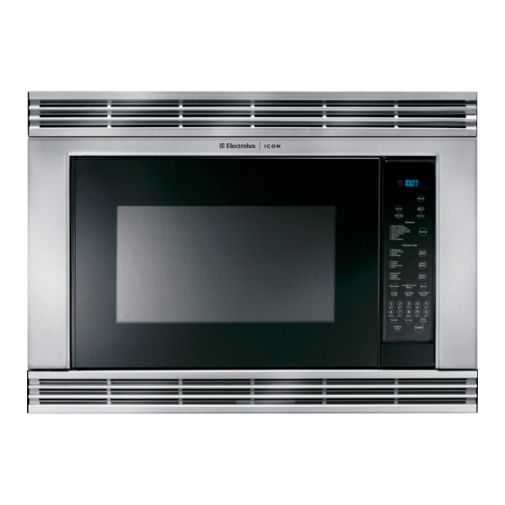
Page 12: Oven Diagram
Basic Information Oven Diagram Touch Control Panel 1. Ventilation openings. (Rear side) 2. Oven door with see-through window. 3. Oven lamp. 4. Turntable support. 5. Removable turntable. The turntable will rotate clockwise or counterclockwise. 6. Safety door latches. The oven will not operate unless the door is securely closed. -
Page 13: Section 2 Operation
Operation 2. 117 volts AC is supplied to the primary winding of Operating Sequence Description the power transformer and is converted to about The following is a description of component functions 3.0 volts AC output on the filament winding, and during oven operation. - Page 14 Operation SCHEMATIC NOTE: Condition Of Oven 1. Door closed. 2. Clock appears on display. CONV. MAGNETRON OVEN THERMAL THERMAL THERMAL NOISE FILTER CUT-OUT CUT-OUT CUT-OUT COM. (RY1) N.O. (RY1) POWER TRANSFORMER COM. (RY3) COM. SECONDARY (RY2) INTERLOCK N.O. CONTROL UNIT RERAY (RY2) CAPACITOR...
- Page 15 Operation SCHEMATIC NOTE: Condition Of Oven 1. Door closed. 2. Mix cooking pad touched. 3. Cooking time programmed. 4. “Start” pad touched. 5. RY2 and RY3 will alternately close during cook cycle. CONV. MAGNETRON OVEN THERMAL THERMAL THERMAL NOISE FILTER CUT-OUT CUT-OUT CUT-OUT...
-
Page 16: Variable Cooking
Operation 2. Heat Potatoes. Moisture and humidity is emitted Variable Cooking rapidly. You can smell the aroma as it cooks. When Variable Cooking Power is programmed, 117 volts AC is supplied to the power transformer intermittently through the contacts of relay (RY-2) and is operated by the control unit within a varying time base. -
Page 17: Convection Cooking Condition
Operation Convection Cooking Condition 4. Upon completion of cooking time, the audible signal will sound, and oven lamp, turntable motor, cooling PREHEATING CONDITION fan motor and convection motor are de-energized. At the end of the convection cycle, if the cavity air Program desired convection temperature by touching the temperature is above 275°F, the circuit to RY6 will CONVECTION pad and the TEMPERATURE pad. - Page 18 Operation The relationship between the convection and microwave 3. The shut-off relays (RY1, RY5 and RY6) are power operations are as follows. energized, turning on the oven lamp, turntable motor, cooling fan motor and convection motor. The power supply voltage is applied to the heating element. 4.
-
Page 19: Touch Control Panel Assembly
Operation 2. Step 1 is repeated. If the difference between the first 1. LSI voltage measured (in step 1) and voltage measured This LSI controls the temperature measurement when the procedure is repeated (step 2) is greater signal, AH sensor signal, key strobe signal, relay than 300mV, the LSI makes the judgment that there driving signal for oven function and indicator signal. -
Page 20: Component Descriptions
Operation Component Descriptions MONITOR SWITCH The monitor switch is mounted on the middle position of DOOR SENSING AND PRIMARY INTERLOCK latch hook. It is activated (the contacts opened) by the SWITCHES lower latch head while the door is closed. The switch is intended to render the oven inoperative by means of The door sensing switch in the secondary interlock system is mounted in the upper position on the latch... - Page 21 Operation CONVECTION COOKING SYSTEM OVEN THERMAL CUT-OUT This oven is designed with a hot air heating system The thermal cut-out located on the side of the steam duct where food is not directly heated by the heating element, is designed to prevent damage to the unit if the foods in but is heated by forced circulation of the hot air produced the oven catch fire due to over heating produced by by the heating element.
- Page 22 Operation DAMPER OPEN-CLOSE MECHANISM Usually, the damper is in the open position except during convection cooking. Damper position is set automatically by damper motor, damper switch, motor cam and damper Damper Shaft shaft. These components are operated by a signal that judges if microwave cooking or convection cooking operation is selected by the control unit.
-
Page 23: Humidity Sensor Circuit
Operation (3) Detector Circuit of Absolute Humidity Sensor Humidity Sensor Circuit Circuit: (1) Structure of Absolute Humidity Sensor: This detector circuit is used to detect the output voltage The absolute humidity sensor includes two thermistors as of the absolute humidity circuit to allow the LSI to control shown in the illustration below. - Page 24 Operation Notes 2-12...
-
Page 25: Section 3 Troubleshooting And Testing
Troubleshooting and Testing Troubleshooting Guide When troubleshooting the microwave oven, it is helpful to follow the Sequence of Operation in performing the checks. Many of the possible causes of trouble will require that a specific test be performed. These tests are given a procedure letter which will be found in the “Test Procedure “section. - Page 26 Troubleshooting and Testing...
-
Page 27: Test Procedures
Troubleshooting and Testing Test Procedures Procedure Component Test Letter MAGNETRON ASSEMBLY TEST HIGH VOLTAGES ARE PRESENT DURING THE COOK CYCLE, SO EXTREME CAUTION SHOULD BE OBSERVED. DISCHARGE THE HIGH VOLTAGE CAPACITOR BEFORE TOUCHING ANY OVEN COMPONENTS OR WIRING. 1. Disconnect the power supply cord, and then remove outer case. 2. - Page 28 Troubleshooting and Testing Procedure Component Test Letter POWER TRANSFORMER TEST DO NOT TOUCH THE COMPONENTS OF THE POWER TRANSFORMER WHILE POWER TRANSFORMER IS ENERGIZED. IT IS DANGEROUS BECAUSE THIS HAS HIGH VOLTAGE COMPONENTS. (HIGH VOLTAGES ARE PRESENT AT THE HIGH VOLTAGE TERMINAL, SO DO NOT ATTEMPT TO MEASURE THE FILAMENT AND HIGH VOLTAGE.) 1.
- Page 29 Troubleshooting and Testing Procedure Component Test Letter HIGH VOLTAGE CAPACITOR TEST 1. Disconnect the power supply cord, and then remove outer case. 2. Open the door and block it open. 3. Discharge high voltage capacitor. (See Warnings and Instructions on page 3-1) 4.
- Page 30 Troubleshooting and Testing Procedure Component Test Letter SECONDARY INTERLOCK RELAY 1. Disconnect the power supply cord, and then remove outer case. 2. Open the door and block it open. 3. Discharge high voltage capacitor. 4. Disconnect two (2) wire leads from the male tab terminals of the secondary interlock relay (RY2).
- Page 31 Troubleshooting and Testing Procedure Component Test Letter BLOWN MONITOR FUSE 1. Disconnect the power supply cord, and then remove outer case. 2. Open the door and block it open. 3. Discharge high voltage capacitor. (See Warnings and Instructions on page 3-1) 4.
- Page 32 Troubleshooting and Testing Procedure Component Test Letter CONVECTION CUT-OUT (on side of the heater duct) 1. Disconnect the power supply cord, and then remove outer case. 2. Open the door and block it open. 3. Discharge high voltage capacitor. (See Warnings and Instructions on page 3-1) 4.
- Page 33 Troubleshooting and Testing Procedure Component Test Letter DAMPER MOTOR TEST 1. Disconnect the power supply cord, and then remove outer case. 2. Open the door and block it open. 3. Discharge high voltage capacitor. (See Warnings and Instructions on page 3-1) 4.
- Page 34 Troubleshooting and Testing Procedure Component Test Letter NOISE FILTER TEST 1. Disconnect the power supply cord, and then remove outer case. 2. Open the door and block it open. 3. Discharge high voltage capacitor. 4. Disconnect the leads to the primary of the power transformer. 5.
- Page 35 Troubleshooting and Testing Procedure Component Test Letter TOUCH CONTROL PANEL ASSEMBLY TEST The touch control panel consists of circuits including semiconductors such as LSI, ICs, etc. Therefore, unlike conventional microwave ovens, proper maintenance cannot be performed with only a voltmeter and ohmmeter. In this service manual, the touch control panel assembly is divided into two units, Control Unit and Key Unit, and also the Control Unit is divided into two units, LSI Unit and Power Unit, and troubleshooting by unit replacement is described according to the symptoms indicated.
- Page 36 Troubleshooting and Testing Procedure Component Test Letter 2. Control Unit The following symptoms indicate a defective control unit. Before replacing the control unit, perform the Key unit test (Procedure Q) to determine if control unit is faulty. 2-1. In connection with pads. 1.
- Page 37 Troubleshooting and Testing Procedure Component Test Letter KEY UNIT TEST If the display fails to clear when the STOP/CLEAR pad is depressed, first verify the flat ribbon cable is making good contact, verify that the door sensing switch (stop switch) operates properly; that is the contacts are closed when the door is closed and open when the door is open.
- Page 38 Troubleshooting and Testing Procedure Component Test Letter COMPU DEFROST TEST WARNING : The oven should be fully assembled before following procedure. 1. Place one cup of water in the center of the turntable tray in the oven cavity. 2. Close the door. touch the “COMPU DEFROST” pad twice and touch the Number pad “5”. Then touch the “START”...
- Page 39 Troubleshooting and Testing Procedure Component Test Letter AH SENSOR TEST Checking the initial sensor cooking condition. 1. The oven should be plugged in at least two minutes before sensor cooking. 2. Room temperature should not exceed 95°F (35°C). 3. The unit should not be installed in any area where heat and steam are generated. The unit should not be installed, for example, next to a conventional surface unit.
- Page 40 Troubleshooting and Testing Procedure Component Test Letter TESTING METHOD FOR AH SENSOR AND/OR CONTROL UNIT To determine if the sensor is defective, the simplest method is to replace it with a new replacement sensor. 1. Disconnect oven from power supply and remove outer case. 2.
- Page 41 Troubleshooting and Testing Description of LSI The I/O signals of the LSI(IXA103DR) are detailed in the following table. Pin# Signal Description Connected to GND. Anode (segment) of Fluorescent Display light-up voltage: -30V. Vp voltage of power source circuit input. AVSS Power source voltage: -5V.
- Page 42 Troubleshooting and Testing Pin# Signal Description Magnetron high-voltage circuit driving signal. To turn on and off the cook relay(RY2). In P-HI operation, the signals holds “L” level during microwave cooking and “H” level while not cooking. In other cooking modes (P-90, P-80, P-70, P-60, P-50, P-40, P-30, P-20, P-10, P-0) the signal turns to “H”...
- Page 43 Troubleshooting and Testing Pin# Signal Description Signal coming from touch key. When any one of G-1 line keys on key matrix is touched, a corresponding signal from P10 - P17 will be input into P27. When no key is touched, the signal is held at “L” level. Signal similar to P27.
- Page 44 Troubleshooting and Testing Pin# Signal Description Segment data signal. Signal similar to P23. Key strobe signal. Signal applied to touch-key section. A pulse signal is input to P24-P27 terminal while one of G-5 line keys on key matrix is touched. 49-53 P07- Segment data signal.
-
Page 45: Section 4 Component Teardown
Component Teardown TO PREVENT AN ELECTRIC SHOCK, TAKE THE FOLLOWING PRECAUTIONS: 1. BEFORE WIRING: 1) Disconnect the power supply. 2) Open the door and wedge the door open. 3) Discharge the high voltage capacitor and wait for 60 seconds. 2. DO NOT LET WIRE LEADS TOUCH TO THE FOLLOWING PARTS: 1) High voltage parts: Magnetron, High voltage transformer, High voltage capacitor and High voltage rectifier assembly. -
Page 46: Outer Case Removal
Component Teardown 4. After re-installing the transformer, secure the Outer Case Removal transformer with two screws to the base cabinet, one is with outer tooth washer and the other is without outer-tooth washer. 5. Re-connect the wire leads (primary and high voltage) 1. -
Page 47: High Voltage Rectifier Assembly Removal
Component Teardown ® High Voltage Rectifier Assembly Positive Lock Connector (No-Case Removal Type) Removal 1. Disconnect oven from power supply and remove ® 1. Push the lever of positive lock connector. outer case. ® 2. Pull down on the positive lock connector. -
Page 48: Convection Motor Removal
Component Teardown Convection Motor Removal Damper Assembly Removal 1. Disconnect oven from power supply and remove 1. Disconnect oven from power supply and remove outer case. outer case. 2. Discharge the high voltage capacitor. 2. Discharge the high voltage capacitor. To discharge the high voltage capacitor, wait for 60 To discharge the high voltage capacitor, wait for 60 seconds and then short-circuit the connection of... -
Page 49: Oven Lamp And Lamp Socket Removal
Component Teardown HEATING ELEMENT REMOVAL 1. Remove two (2) screws holding heating element to heater duct. 2. Loosen two (2) screws holding holders to heater duct and take heating element out of heating element holders. Heating element is free. After completely installing the heating element, bend the top of the heating element holder to inside using by long nose pliers as shown in the Figure 4-3. - Page 50 Component Teardown 15. Remove the fan blade from the fan motor shaft 3. Reset the fan duct assembly to its place. according the following procedure. 4. Install the tabs of fan duct to the rear cabinet and air guide. a. Hold the edge of the rotor of the fan motor by 5.
-
Page 51: Servicing The Touch Control Panel
Component Teardown Power Supply Cord Replacement Servicing The Touch Control Panel Removal Precautions For Handling Electronic Components 1. Disconnect the oven power supply cord and remove This unit uses CMOS LSI in the integral part of the outer case. circuits. When handling these parts, the following precautions should be strictly followed. -
Page 52: Control Panel Assembly And Control Unit Removal
Component Teardown while keeping it connected to the oven. Control Panel Assembly And Control b) On some models, the power supply cord between Unit Removal the touch control panel and the oven proper is long enough that they may be separated from each other. 1. -
Page 53: Switch And Monitor Switch Adjustment
Component Teardown Third Door Switch, Door Sensing Third Door Switch, Door Sensing Switch, Primary Interlock Switch And Switch, Primary Interlock Switch And Monitor Switch Removal Monitor Switch Adjustment Removal If the door sensing switch, third door switch, primary interlock switch and monitor switch do not operate 1. -
Page 54: Door Replacement
Component Teardown Door Replacement And Adjustment Removal The door on a microwave oven is designed to act 1. Disconnect oven from power supply and remove the as an electronic seal preventing the leakage of outer case. Remove turntable tray and turntable microwave energy from the oven cavity during the support from oven cavity. -
Page 55: Door Disassembly
Component Teardown Door Disassembly Remove door assembly, refer to “Door Replacement”. Replacement of door components are as follows: 1. Place door assembly on a soft cloth with latches facing up. As the engaging part of choke cover and door panel are provided at several places, do not force any particular part. - Page 56 Component Teardown Notes 4-12...
-
Page 57: Turntable Motor Removal
Wiring Diagrams Wiring Schematic Oven Off Condition FUSE SCHEMATIC NOISE SUPPRESSION COIL NOTE: Condition Of Oven 1. Door closed. 0.022µ/AC250V 2. Clock appears on display. 0.0033µ/AC125V 0.0033µ/AC125V OVEN LAMP TURNTABLE MOTOR FAN MOTOR CONVECTION MOTOR DAMPER MOTOR HEATIMG ELEMENT PRIMARY INTERLOCK SWITCH MONITOR SWITCH H.V. -
Page 58: Pictorial Diagram
Wiring Diagrams Pictorial Diagram... - Page 59 Wiring Diagrams Control Panel Circuit Diagram...
-
Page 60: Wiring Diagrams
Wiring Diagrams Printed Circuit Board (C81) R86(J8) (C80) (R45) (C45) (CN - D) (R47) (R48) (R49) (C46) (C47) (J7) (J5) (J3) (J2) (J4) (J6) CONV HEATER COM... -
Page 61: Section 6 Parts List
Parts List Key Unit And Door Assembly... - Page 62 Parts List Remainder of Parts List is on Page 6-4.
- Page 63 Parts List Oven And Cabinet Parts...
- Page 64 Parts List Packing And Accessories...