Furuno GP-3500 Installation Manual
Color gps/plotter gp-3500
Hide thumbs
Also See for GP-3500:
- Operator's manual (192 pages) ,
- Operator's manual (2 pages) ,
- Operator's manual (2 pages)
Table of Contents
Advertisement
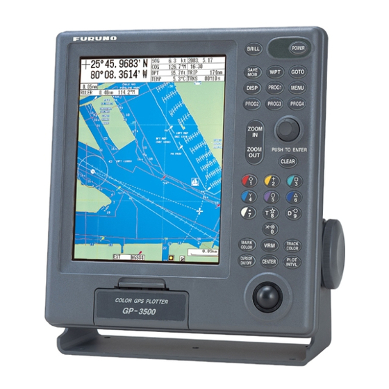
COLOR GPS/PLOTTER GP-3500
SAFETY INSTRUCTIONS..................................................................................... ii
SYSTEM CONFIGURATION................................................................................ iii
EQUIPMENT LISTS ............................................................................................. iv
1. INSTALLATION ................................................................................................ 1
1.1 Installation of Display Unit ............................................................................................... 1
1.2 Installation of Antenna Unit.............................................................................................. 4
2. WIRING............................................................................................................. 5
3. ADJUSTMENTS ............................................................................................... 9
3.1 Display Settings .............................................................................................................. 9
3.2 Navigator Settings......................................................................................................... 13
3.3 I/O Port Settings............................................................................................................ 15
3.4 Sub Track Settings........................................................................................................ 18
3.5 Connection of External Monitor ..................................................................................... 20
OUTLINE DRAWINGS
INTERCONNECTION DIAGRAM
Installation Manual
Back
Advertisement
Table of Contents

Related Manuals for Furuno GP-3500


Summary of Contents for Furuno GP-3500
-
Page 1: Table Of Contents
Back Installation Manual COLOR GPS/PLOTTER GP-3500 SAFETY INSTRUCTIONS..................ii SYSTEM CONFIGURATION................iii EQUIPMENT LISTS ..................... iv 1. INSTALLATION ....................1 1.1 Installation of Display Unit ....................1 1.2 Installation of Antenna Unit....................4 2. WIRING......................5 3. ADJUSTMENTS ....................9 3.1 Display Settings ...................... - Page 2 *00014677800* *00014677800* *00014677800* *00014677800* ( ( DAMI DAMI ) ) GP-3500 GP-3500 * 0 0 0 1 4 6 7 7 8 0 0 * * 0 0 0 1 4 6 7 7 8 0 0 * *IME44210A00* *IME44210A00*...
-
Page 3: Safety Instructions
SAFETY INSTRUCTIONS WARNING CAUTION ELECTRICAL SHOCK HAZARD Observe the following compass safe Do not open the equipment distances to prevent interference to a unless totally familiar with magnetic compass: electrical circuits and service manual. Standard Steering compass compass Only qualified personnel Display 0.60 m 0.40 m... -
Page 4: System Configuration
SYSTEM CONFIGURATION ANTENNA UNIT GPA-017S or GPA-019S (option) Receives GPS signal from GPS satellites. DISPLAY UNIT GP-3500 External Calculates own ship’s Monitor position in latitude and longitude from the signal received Remote from the antenna Controller unit and displays it on the screen. -
Page 5: Equipment Lists
EQUIPMENT LISTS Standard supply Name Type Code No. Remarks Display Unit GP-3500 — Antenna Unit GPA-017S — Installation CP14-06200 000-040-769 With CP20-01111, Materials* CP14-06201, TNC-PS-3D-15, MJ-A3SPF0013-035 CP14-06220 000-040-804 With CP14-06201, MJ-A3SPF0013-035 Spare Parts* SP14-03101 004-363-080 3A fuse * See list at back of this manual. -
Page 6: Installation
1. INSTALLATION 1.1 Installation of Display Unit The display unit may be mounted on a desktop, overhead or flush mounted in a console. Mounting considerations Choose a mounting location for the display unit considering the following points: • Choose a location where the controls be easily operated. •... - Page 7 Mounting Desktop, overhead mounting 1. Fix the hanger to the mounting location with four tapping screws (5X20). See the outline drawing on page D-1 for mounting dimensions. 2. Loosely screw knob bolts into the display unit. 3. Set the display unit to the hanger and tighten the knob bolts. Display unit, mounting dimensions for desktop or overhead mounting 4.
- Page 8 Flush mounting If the thickness of the console is 11-14 mm, use the washer head screws (M4X20) supplied with the installation materials. If it is thicker than those dimensions, the length of the screws should be the thickness of the console plus 7.3 mm ±1.5 mm. The length of the threaded portion to be inserted to the display unit should not exceed 7 mm (B≤7).
-
Page 9: Installation Of Antenna Unit
1.2 Installation of Antenna Unit Refer to the antenna unit outline drawing at the back of this manual for mounting instructions. When selecting a mounting location consider the following points: • Select a location out of the radar and Inmarsat beams. Those beams will obstruct or prevent reception of the GPS satellite signal. -
Page 10: Wiring
2. WIRING Display unit, rear view Power source The power source is a 12 or 24 VDC battery. Be sure the power cable is tightly fastened to the power source and the polarity (plus and minus) is correct. Connect the white lead to the positive terminal(+) and the black lead to the negative terminal(-). - Page 11 Ground Connect the ground wire to the boat’s grounding bus. If the unit is not grounded noise may result. If noise is a problem on an FRP vessel, fasten a ground plate of 20 cm X 30 cm to the outside of the ship’s hull and connect the ground wire there. Use a closed-type lug ( ) for the connection on the display unit.
- Page 12 Waterproofing the connector After connecting the antenna cable, wrap the connector with self-vulcanizing tape and then vinyl tape to waterproof it. Bind ends of vinyl tape with cable ties to prevent unraveling. How to waterproof the connector...
- Page 13 How to attach N-P-8DFB connector Dimensions in millimeters. Outer Sheath Armor Inner Sheath Shield Remove outer sheath and armor by the dimensions shown left. Expose inner sheath and shield by the dimensions shown left. Cover with heat-shrink tubing and heat. Cut off insulator and core by 10 mm.
-
Page 14: Adjustments
3. ADJUSTMENTS 3.1 Display Settings Sensor calibration 1. Press the [MENU] key to open the menu. MENU 1. WAYPOINTS LIST 2. ROUTES LIST 3. MEMORY CARD OPERATIONS & DATA TRANSFER 4. MARKS/SHIP’S TRACKS SETUP 5. MARKS/SHIP’S TRACKS EDITION 6. ALARM SETUP 7. - Page 15 2. Press the [0] and [1] keys to show the DISPLAY SETUP menu. This menu has two pages. 0-1. DISPLAY SETUP NEXT PAGE LANGUAGE 1. ENGLISH KEY BEEP 1. ON 2. OFF SPEED SOURCE 1. INT GPS 2. NMEA SOG 3. NMEA STW NMEA SPEED CALIB +00% (-50-+50%)
- Page 16 4. Rotate the knob to choose NMEA SPEED CALIB and then roll the trackball rightward or leftward as appropriate to display appropriate offset value. For example, if the actual speed is 10.0 kt and the displayed value is11.0 kt, enter +10(%). 5.
- Page 17 Ship and antenna characteristics 1. Display page 1 of the DISPLAY SETUP and then rotate the knob to choose NEXT PAGE. 0-1. DISPLAY SETUP PREVIOUS PAGE WAYPOINT STATUS 1. ON 2. OFF WAYPOINT INFO 1. ON 2. OFF MARK STATUS 1.
-
Page 18: Navigator Settings
3.2 Navigator Settings Choose source of position data as follows: 1. Press the [MENU] key to display the menu. 2. Press the [0] and [2] keys to shown the NAVIGATOR SETUP menu. 0-2 NAVIGATOR SETUP SELECT NAV SOURCE . INT 2. - Page 19 Antenna height The default antenna height (above the waterline) is 5 m. If the height of your antenna is different enter its height as follows: 1. At the NAVIGATOR SETUP menu, rotate the knob to choose ANTENNA HEIGHT. 2. Enter height with the numeric keys. 3.
-
Page 20: I/O Port Settings
3.3 I/O Port Settings NMEA1 and NMEA2 ports NMEA 1 and NMEA 2 ports are used to connect external navigation equipment such as an autopilot and radar. Set up the ports according to equipment connected. 1. Press the [MENU] key to open the menu. 2. - Page 21 4. Rotate the knob to choose TLL OUTPUT and then roll the trackball rightward or leftward to choose appropriate option. ON outputs latitude and longitude position of mark entered with a mark key. 5. Rotate the knob to choose L/L FORMAT and then roll the trackball rightward or leftward to choose appropriate option.
- Page 22 8. Rotate the knob to place the cursor on the sentence to process. 9. Push the knob to display ON or OFF as appropriate. 10. Repeat steps 8 and 9 to process other sentences. 11. Press the [MENU] key several times to close the menu. I/O format Port I/O format...
-
Page 23: Sub Track Settings
3.4 Sub Track Settings Sub track is the ship’s track drawn using the NMEA signal from external equipment. To display sub track, set talker of external equipment as follows: 1. Press the [MENU] and [4] keys to show the MARK/SHIP’S TRACK SETUP menu. 4. - Page 24 4. MARKS/SHIP’S TRACKS SETUP PREVIOUS PAGE DISP TARGET TRACKS 1. ON 2. OFF TARGET TRACK COLOR TARGET TRACK STYLE DISP SUB TRACKS 1. ON 2. OFF SUB TRACKS COLOR SUB TRACK STYLE SUB TRACK TALKER 1. GP 2. II 3. IN 4.
-
Page 25: Connection Of External Monitor
3.5 Connection of External Monitor Use the optional external monitor connection kit to connect a VGA monitor as a remote display. External Monitor Connection Kit Type: OP03-176, Code No.: 008-526-360 Name Type Code No. Remarks Cable Assy. 15SDS/XHP10-005 000-144-511 0.5 m, Mini D-sub 15P Grommet MG-4 000-871-378... - Page 26 5. Open a hole in the OPTION grommet in order to pass the cable assy. 6. Referring to the illustration below for location, unfasten the four screws marked with the triangles. On the MAIN Board (14P0379), disconnect the mini-pin coaxial connector from J15 and the cable assy.
- Page 27 7. Pass the cable assy. through the OPTION grommet and connect it to J13 on the MAIN Board. Display unit, rear view, rear cover removed 8. Fix the GPS receiver assy. on top of the MAIN Board (14P0379). Use one of the screws to fasten the ground terminal of the cable assy.
-
Page 28: Packing List
A - 1 14CQ-X-9851 -4 PACKING LIST PACKING LIST PACKING LIST PACKING LIST GP-3500/F-E-C/N GP-3500/F-E-C/N GP-3500/F-E-C/N GP-3500/F-E-C/N N A M E DESCRIPTION/CODE № O U T L I N E Q'TY ユニット ユニット UNIT UNIT ユニット ユニット UNIT UNIT GP-3500-E 指示器 DISPLAY UNIT (*1) - Page 29 A - 2 004-364-040 14CQ-X-9401 CODE NO. CODE NO. CODE NO. CODE NO. TYPE TYPE TYPE TYPE CP14-06231 工事材料表 工事材料表 工事材料表 工事材料表 INSTALLATION MATERIALS 番 号 名 称 型名/規格 数量 略 図 用途/備考 Q'TY OUTLINE NAME DESCRIPTIONS REMARKS ユーザー貼りマーク 14-072-1094-0 USER LABEL CODE NO.
- Page 30 A - 3...
- Page 31 A - 4...
- Page 32 D - 1...
- Page 33 D - 2...
- Page 34 D - 3...
- Page 35 D - 4 Feb. 19, '03...
- Page 36 D - 5 Feb. 19, '03...
- Page 37 D - 6 Jan. 30, '03...
- Page 38 S - 1...