3Com 7250 Quick Start Manual
Hide thumbs
Also See for 7250:
- Datasheet (4 pages) ,
- User manual (66 pages) ,
- Conversion manual (10 pages)
Table of Contents
Advertisement
Quick Links
Wireless LAN Access Point 7250
3CRWE725075
The 3Com Wireless LAN Access Point 7250 offers enterprise network standard based security and complete
centralized management, with flexible and expansive connectivity and scalability. It extends networks and
boosts productivity for centrally managed enterprises requiring scalable security solutions.
NOTE: This product must be installed by a professional technician/installer.
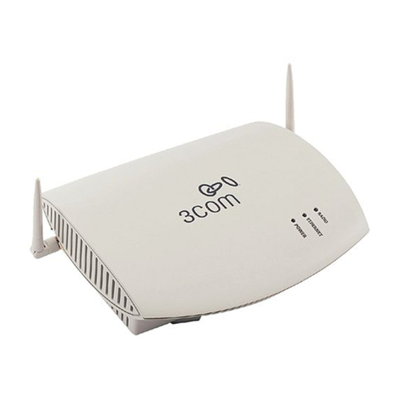
Access Point 7250 - Front
Access Point 7250 - Back
CAUTION: Do not connect a telephone cable into the Ethernet port; doing so can cause serious
!
damage to the access point.
Quick Start Guide
Console port
Ethernet port
1
Power supply
Advertisement
Table of Contents

Related Manuals for 3Com 7250


Summary of Contents for 3Com 7250
-
Page 1: Quick Start Guide
Wireless LAN Access Point 7250 3CRWE725075 The 3Com Wireless LAN Access Point 7250 offers enterprise network standard based security and complete centralized management, with flexible and expansive connectivity and scalability. It extends networks and boosts productivity for centrally managed enterprises requiring scalable security solutions. -
Page 2: Before You Start
Observe the following power requirements: The access point complies with the IEEE 802.3af power-over-Ethernet standard. It receives power over category 5 straight cable. Installation requires the use of either the 3Com power supply provided or IEEE 802.3af compliant power supply equipment (output power rated 48 V DC @ 350 mA maximum). -
Page 3: Connect The Power
IEEE 802.3af standard. Using the Included AC Adapter The power supply included with the Access Point 7250 is an AC adapter. Follow these steps to connect the AC adapter: Connect the power cord to the power supply and plug the cord into a power outlet. -
Page 4: Using An Optional Power-Over-Ethernet Injector
Using An Optional Power-Over-Ethernet Injector The Power-Over-Ethernet Injector can be located at any point between the access point and the LAN access port, wherever a convenient power outlet exists. If you supply your own Ethernet cable for connecting power, be sure that it is standard category 5 straight-through (8-wire) cable that has not been altered in any way. Use of nonstandard cable could damage the access point. -
Page 5: Check The Leds
Check the LEDs When power is connected, the access point LEDs light up. The illustration and the following table describe the LEDs and their functions. Name Description Radio LED blinks red to indicate radio activity. Faster blinking indicates more activity. Ethernet LED lights yellow when 10 Mbps Ethernet link is established. -
Page 6: Flat Surface Installation
If you have routed the Ethernet cable through the center opening, secure the cable on the hook located on the mounting plate as shown in the illustration below. Connect the Ethernet cable to the Ethernet port on the access point. Connect the power cable to the power port on the rear panel of the access point. -
Page 7: Antenna Adjustment
IP devices, including 3Com wireless access points. It is not required for access point management. 3Com Site Survey Tool. This utility assists in selecting the best location for your access point before installing the device permanently. Use the Site Survey Tool to determine if the intended mounting locations will provide adequate coverage with good signal strength and quality. -
Page 8: Configuration Notes
Configuration Notes For a new access point installation, the default WLAN Service Area (ESSID) is 3Com and no security is set. Unless it detects a DHCP server on the network, the access point uses Auto IP to assign an IP address of the form 169.254.2.1.