Table of Contents
Advertisement
PL12FK
1
PL18FK2
1
PL24FK2
1
PL30FK2
1
PL36FK3
1
PL42FK2
1
CONTENTS
1. TECHNICAL CHANGE ··················································································OC194- 2
2. FEATURES ····································································································OC194- 3
3. PART NAME AND FUNCTIONS ····································································OC194- 4
4. SPECIFICATIONS ··························································································OC194- 6
5. DATA ··············································································································OC194- 8
6. OUTLINES AND DIMENSIONS ····································································OC194-17
7. REFRIGERANT SYSTEM DIAGRAM ····························································OC194-19
8. WIRING DIAGRAM ························································································OC194-20
9. OPERATION FLOW-CHART··········································································OC194-22
10. MICROPROCESSOR CONTROL ··································································OC194-25
11. TROUBLESHOOTING ····················································································OC194-36
12. 4-WAY AIR FLOW SYSTEM ········································································OC194-43
13. SYSTEM CONTROL ······················································································OC194-50
14. DISASSEMBLY PROCEDURE ······································································OC194-55
15. PARTS LIST ··································································································OC194-57
16. OPTIONAL PARTS ························································································OC194-63
OC194-1
Advertisement
Table of Contents

Related Manuals for Mitsubishi Electric PL42FK21


Summary of Contents for Mitsubishi Electric PL42FK21
-
Page 1: Table Of Contents
PL12FK PL18FK2 PL24FK2 PL30FK2 PL36FK3 PL42FK2 CONTENTS 1. TECHNICAL CHANGE ··················································································OC194- 2 2. FEATURES ····································································································OC194- 3 3. PART NAME AND FUNCTIONS ····································································OC194- 4 4. SPECIFICATIONS ··························································································OC194- 6 5. DATA ··············································································································OC194- 8 6. OUTLINES AND DIMENSIONS ····································································OC194-17 7. REFRIGERANT SYSTEM DIAGRAM ····························································OC194-19 8. -
Page 2: Technical Change
TECHNICAL CHANGE Differences with OC001 which is a basic service manual. Change points o 4- o 4- Appearances No.9 Switch for temperature unit Canceled SW17 Remote Dip switch No.0 Canceled Switch for louvers controller SW18 — Addition of "Mode selector" No.10 No.3 Control change of the normal and twin... -
Page 3: Features
FEATURES SWING TIMER OFF TIMER CLOCK AUTO AUTO CHECK SET TEMP. START STOP FILTER SPEED AUTO CHECK MODE RETURN TEST RUN Remote controller Indoor Unit Models Cooling capacity SEER PL12FK 12,300 Btu/h 10.4 PL18FK2 18,400 Btu/h 10.2 PL24FK2 23,600 Btu/h 10.0 PL30FK2 31,000 Btu/h... -
Page 4: Part Names And Functions
PART NAMES AND FUNCTIONS Remote controller Once the controls are set, the same operation mode can be repeated by simply pressing the ON / OFF button. Remote controller operation buttons CLOCK/TIMER button TIMER ON/OFF button This sets or switches the current time,start time and stop time. -
Page 5: Remote Controller Display
Remote controller display In this display example on the bottom left, a condi- CENTRALLY CLOCK display tion where all display lamps light is shown for CONTROLLED display explanation purposes although this differs from The current time , start time and stop time can be displayed in ten second actual operation. -
Page 6: Specifications
SPECIFICATIONS MODELS : PL12FK , PL18/24FK2 Model PL18FK2 PL24FK2 PL12FK Item Capacity Btu/h 18,400 23,600 112,300 Power Consumption 1.88 2.48 1.23 10.0 SEER 10.2 10.0 10.4 INDOOR UNIT MODELS PL18FK2 PL24FK2 PL12FK External finish Galvanized sheets with gray heat insulation Power supply V,phase,Hz 115 , 1 , 60... - Page 7 MODELS : PL30FK2 , PL36FK3 , PL42FK2 Model PL36FK3 PL42FK2 PL30FK2 Item Capacity Btu/h 36,100 42,500 31,000 Power Consumption 3.76 4.40 3.10 10.0 SEER 10.0 10.0 10.4 INDOOR UNIT MODELS PL36FK3 PL42FK2 PL30FK2 External finish Galvanized sheets with gray heat insulation Power supply V,phase,Hz 115 , 1 , 60...
-
Page 8: Data
DATA MODELS : PL12FK , PL18/24/30FK2 , PL36FK3 , PL42FK2 1. PERFORMANCE DATA 1) COOLING CAPACITY Indoor air Outdoor intake air DB temperature ( °F ) Airflow Models ( CFM ) ( °F ) 14.3 1.06 13.8 1.16 13.2 1.27 12.6 1.38 11.9... -
Page 9: Performance Curve
2. PERFORMANCE CURVE NOTES : A point on the curve shows the reference point. PL12FK COOLING CAPACITY PL18FK2 COOLING CAPACITY SHF=0.77 SHF=0.76 Indoor intake air WB temperature ( F) Indoor intake air WB temperature ( F) Indoor intake air WB temperature ( F) Indoor intake air WB temperature ( F) 32 35 65 (67) 75... - Page 10 NOTES : A point on the curve shows the reference point. PL24FK2 COOLING CAPACITY PL30FK2 COOLING CAPACITY SHF=0.76 SHF=0.71 Indoor intake air WB temperature ( F) Indoor intake air WB temperature ( F) Indoor intake air WB temperature ( F) Indoor intake air WB temperature ( F) 32 35 65 (67) 75...
-
Page 11: Cooling Mode
3. CONDENSING PRESSURE AND SUCTION PRESSURE Data is based on the condition of indoor humidity 50%. Air flow should be set at HI. A point on the curve shows the reference point. <PL12FK > COOLING MODE (psi.G) (psi.G) Indoor DB temperature( F) Indoor DB temperature( F) DB( F) - Page 12 Data is based on the condition of indoor humidity 50%. Air flow should be set at HI. A point on the curve shows the reference point. <PL24FK2 > COOLING MODE (psi.G) (psi.G) Indoor DB temperature( F) Indoor DB temperature( F) DB( F) DB( F) Outdoor ambient temperature...
- Page 13 Data is based on the condition of indoor humidity 50%. Air flow should be set at HI. A point on the curve shows the reference point. <PL36FK3 > COOLING MODE (psi.G) (psi.G) Indoor DB temperature( F) Indoor DB temperature( F) DB( F) DB( F) Outdoor ambient temperature...
-
Page 14: Standard Operation Data
4. STANDARD OPERATION DATA Model PL42FK2 PL12FK PL18FK2 PL24FK2 PL30FK2 PL36FK3 Item Unit Cooling Cooling Cooling Cooling Cooling Cooling 42,500 Capacity Btu / t 12,300 18,400 23,600 31,000 36,100 — 0.77 0.76 0.71 0.76 0.73 0.72 4.40 Input 1.23 1.88 2.48 3.76 INDOOR UNIT MODEL... -
Page 15: Noise Criterion Curves
6.OUTLET AIR SPEED AND COVERAGE RANGE PL12FK PL18FK2 PL24FK2 PL30FK2 PL36FK3 PL42FK2 Airflow (CFM) 1,170 1,170 1,270 Standard Air speed (ft / sec.) 11.3 12.5 10.5 10.5 11.4 height Coverage range (ft) •The air coverage range is the value up to the position where the air speed is 0.8ft/sec. when air is blown out horizontally from the unit at the High fan setting. - Page 16 8. NOISE CRITERION CURVES PL30FK2 PL24FK2 NOTCH SPL(dB) LINE NOTCH SPL(dB) LINE PL36FK3 NC-70 NC-70 NC-60 NC-60 NC-50 NC-50 NC-40 NC-40 NC-30 NC-30 APPROXIMATE APPROXIMATE THRESHOLD OF THRESHOLD OF HEARING FOR HEARING FOR NC-20 NC-20 CONTINUOUS CONTINUOUS NOISE NOISE 1000 2000 4000 8000...
-
Page 17: Outlines And Dimensions
OUTLINES AND DIMENSIONS 1. INDOOR UNIT Unit : inch PL12FK / 18/24FK2 OC194-17... - Page 18 PL30FK2 / 36FK3 / 42FK2 Unit : inch OC194-18...
-
Page 19: Refrigerant System Diagram
Unit : inch 2.Remote controller 5-1/8 3/32 23/32 SWING TIMER OFF TIMER CLOCK AUTO AUTO CHECK SET TEMP. START STOP FILTER SPEED AUTO CHECK MODE RETURN TEST RUN REFRIGERANT SYSTEM DIAGRAM Unit : inch PL12FK PL18/24FK2 Refrigerant pipe (option) {5/8" (with heat insulator) Flared connection Strainer... -
Page 20: Wiring Diagram
WIRING DIAGRAM MODELS PL12FK PL18FK2 PL24FK2 WIRING DIAGRAM SYMBOL NAME SYMBOL NAME SYMBOL NAME Fan motor capacitor SW1<I.B> Switch <mode selector> X1<I.B> Auxiliary relay <drain water lift-up CN1<R.B> Connector <program timer> SW2<I.B> Switch <address selector> mechanism/dew prevention heater > CN2<R.B> Connector <remote switch>... - Page 21 MODELS PL30FK2 PL36FK3 PL42FK2 WIRING DIAGRAM SYMBOL NAME SYMBOL NAME SYMBOL NAME C1,2 Fan motor capacitor SW1<I.B> Switch <mode selector> X1<I.B> Auxiliary relay <drain water lift-up CN1<R.B> Connector <program timer> SW2<I.B> Switch <address selector> mechanism/dew prevention heater > CN2<R.B> Connector <remote switch> SW3<I.B>...
-
Page 22: Operation Flow-Chart
OPERATION FLOW-CHART MAIN OPERATION START Power circuit breaker Check SW ON twice Operation SW “OFF” timer Set time “ON” timer complete Set time complete Trouble Remote controller operation display STOP Trouble STOP Operating mode (COOL) COOL operation PROTECTION DEVICE PROTECTION DEVICE SELF HOLD RELEASE SELF HOLD Operating mode... -
Page 23: Cooling Operation
COOLING OPERATION COOL operation Initial COOLING Vane initial setting Vane 55 deg downward angle 70 deg downward angle Fan speed Downward discharge 1 hour Vane horizontal Vane setting notch airflow Compressor thermostat Allowance cancel 3-minute time delay 6-minute Allowance time delay period 6 minute 3-minute... -
Page 24: Dry Operation
DRY OPERATION operation Initial dry operation Vane Vane initial setting setting notch Room temperature is 64-F or lower During compressor ON 3-minute 3-minute compressor time delay operation Compressor & Compressor & thermostat ON thermostat 10-minute Compressor ON compressor time completes Compressor ON 10-minute compressor OFF timer start... -
Page 25: Microprocessor Control
MICROPROCESSOR CONTROL 1.OUTLINE OF MICROPROCESSOR CONTROL Remote controller board INPUT to remote controller OUTPUT to remote controller Processes and transmits OFF-ON switching. orders. Remote controller COOL/DRY-FAN selector switching. LCD indicator Thermostat setting. TIMER mode selector-switching and Timer setting. SWING TIMER OFF TIMER CLOCK AUTO AUTO HIGH-LOW fan speed switching. -
Page 26: Indoor Unit Control
2. INDOOR UNIT CONTROL 2-1 COOL operation <How to operate> 1 Press POWER ON/OFF button. 2 Press the MODE button to display COOL. 3 Press the SET TEMP. button to set the desired temperature. SWING TIMER OFF TIMER CLOCK AUTO AUTO NOTE: Set temperature changes 2°F when the SET TEMP. - Page 27 5 Coil frost protection When indoor coil temperature becomes 5°F or below,coil frost protection will proceed as follows. <Start condition> After the compressor has been continuously operated for 3 minutes or more,and the indoor coil temperature has been 5°F or below for 3 minutes,the coil frost protection will start. <Coil frost protection>...
- Page 28 (4) Detecting abnormalities in the outdoor unit After the compressor has been continuously operated for 3 minutes, if the difference between the indoor coil temperature and room temperature is out of RANGE C for 1 minute, the indoor fan speed will turn to LOW. Five minutes later, if the dif- ference is still out of RANGE C,the outdoor unit is functioning abnormally.
- Page 29 2-2 DRY operation <How to operate> SWING TIMER OFF TIMER CLOCK AUTO AUTO 1 Press POWER ON/OFF button. CHECK SET TEMP. START STOP FILTER SPEED AUTO CHECK MODE RETURN TEST RUN 2 Press the MODE button to display “DRY” 3 Press the SET TEMP. button to set the desired temperature. NOTE: The set temperature changes 2°F when the SET TEMP.
- Page 30 4The compressor will not start when the room temperature is 64°F or below. The compressor starts intermittent operation when the power is turned ON with room temperature above 64°F. The com- pressor ON/OFF time depends on the thermostat ON/OFF and the following room temperatures.After 3-minute compres- sor operation, If the room temperature thermistor reads above 85°F with thermostat ON, the compressor will operate for 6 more min- utes and then stop for 3 minutes.
- Page 31 2-3 Auto vane control <How to operate> To change the air flow direction, press AIR DISCHARGE button. SWING TIMER OFF TIMER CLOCK AUTO AUTO CHECK SET TEMP. START STOP FILTER SPEED AUTO CHECK MODE RETURN TEST RUN 20° 45° 60° 70°...
- Page 32 2-4 TIMER operation WIRED REMOTE CONTROLLER <Timer function> AUTO STOP ··········The air conditioner stops after the set time lapses. AUTO START ········The air conditioner starts after the set time lapses. AUTO OFF ············Timer is not active. <How to operate> SWING 1.
- Page 33 (1) Indoor coil temperature code During the test run, the indoor coil temperature code from 1 to 15 is displayed on the remote controller instead of room temperature. The code should fall with the lapse of time in normal COOL operation, and should rise in normal HEAT operation.
- Page 34 3 DIP SWITCH FUNCTIONS Each figure shows the initial setting by factory. 3-1 On remote controller board (1) SW17(Address selector) 8 7 6 5 4 3 2 1 SW17-1 ~ 6) Switch for address setting SW17-7) When two remote controllers are used, this switch sets the controller function. OFF : The remote controller is set as a main controller.
-
Page 35: Indoor Fan Control
SW1-6) Switch for set temperature adjustment in heating mode This is not available for series PL. SW1-7) Switch for fan speed during thermostat OFF in heating mode This is not available for series PL. SW1-8) Switch for fan motor operation in heating mode This is not available for series PL. -
Page 36: Troubleshooting
TROUBLESHOOTING 1.TROUBLES IN TEST RUN Symptom Cause Check points The display “CENTRALLY 1) Wrong address setting of remote con- 1) Check the address setting of remote controller CONTROLLED” on remote troller/indoor controller board. and indoor controller. controller does not disap- 2) Timer adapter is connected to the 2) Make sure the timer adapter is used correctly. -
Page 37: Wired Remote Controller
2. SELF DIAGNOSTIC FUNCTION WITH REMOTE CONTROLLER (WIRED REMOTE CONTROLLER) 2-1 When malfunction occurs during operation When a malfunction occurs, the indoor and outdoor units stop and the malfunction is displayed on the LCD of the remote controller. (1) ON the set temperature display part, “CHECK” appears, and the unit CHECK mode address and the check code are displayed alternately at one-second intervals. - Page 38 Check Diagnosis of malfunction Cause Check points code Signal transmitting/receiving During individual unit control 1) Check the transmission wire. error 1) Bad contact of transmission 2) Check with another remote controller. If “E0” is (Indoor controller does not wire still indicated, replace the indoor controller respond to remote controller 2) Signal transmitting/receiving cir- board.
- Page 39 3. WRONG WIRING ON SITE 3-1 Between remote controller and indoor unit If the wire is disconnected between the remote controller and the indoor unit, nothing is displayed on the remote controller when the POWER button is pressed. The beep sound will also not be heard. 3-2 Phenomenon due to wrong wiring between indoor and outdoor units Wrong wiring Thermostat...
- Page 40 4. OTHER TROUBLES AND CAUSES Vanes do not work. Vane motor is damaged. Vane motor does not work. Vane motor relay is damaged. Connector is poorly connected. Vane motor is poorly assembled. Indoor controller board is damaged. Unit stops after 5 to Refer to check code on remote controller display.
- Page 41 4. How to check the parts PL12FK /18FK2 /24FK2 /30FK2 /36FK3 /42FK2 Parts name Check points Room temperature Disconnect the connector then measure the resistance using a tester. thermistor (TH1) (Surrounding temperature 50-F~86-F) Liquid pipe Normal Abnormal (Refer to the thermistor) thermistor (TH2) 4.3k"~9.6k"...
- Page 42 <Thermistor Characteristic graph> < Thermistor for lower temperature > Room temperature thermistor(TH1) Thermistor for Liquid pipe thermistor(TH2) lower temperature Thermistor R =15k' ± 3% Fixed number of B=3480k' ± 2% Rt=15exp { 3480( 273+{(t-32)/1.8} 32°F 15k' 50°F 9.6k' 68°F 6.3k' 104 122 77°F 5.2k'...
-
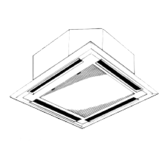
Page 43: Way Air Flow System
4-WAY AIR FLOW SYSTEM Using this grill enables to select the air discharge direction. The air flow can also be regulated by adjusting the widths of each discharge outlet. Choose the adequate method according to the conditions in the room where the panel is to be installed. W For 2-direction discharge, the widths of the outlets must be under a fully opened condition. - Page 44 Opening measurements for PLH30/36/42FK are within ( ). Unit : inch Adjustment examples of discharge direction & air flow 11-13/16 (25-9/16) Regular ceiling height When ceiling is of regular height (For example 8.2ft) set each out- let at a standard width (11-13/16). 8.2ft.
- Page 45 Selecting arrangement of discharge outlet and adjusting the width for PL12FK / 18/24FK2 Unit : inch Constrained Conditions When Selecting Discharge Outlet Width. (PL18/24FK2 Total width of four outlets must exceeds 31-1/2. Discharge outlet Examples of application Precautions W Ceiling height Room pattern ratio of room (1) When the outlet A is close to a window,...
- Page 46 Selecting arrangement of discharge outlet and adjusting the width for PL30FK2 / 36FK3 / 42FK2 Unit : inch Constrained Conditions When Selecting Discharge Outlet Width. (PL30/36/42FK) Total width of four outlets must exceeds 55-1/8. Discharge outlet Examples of application Precautions W Ceiling height Room pattern ratio of room...
- Page 47 FRESH AIR INTAKE (Installation at site) 1. Location for installing fresh air intake The fresh air intake duct can be connected by removing the knockout holes on the casing of the indoor unit and attaching the fresh air intake flange and duct. When applying fresh air intake, confirm that the mixed air is within applicable conditions as the intake air mixes with the ambient air.
- Page 48 BRANCH DUCT (installation at site) To discharge air from a branch duct, install it during the initial installation. 1. Branch Duct Installation Procedure 2. Branch Duct Installation Install branch duct at site by following procedure (1) Remove insulation along the broken-lines on unit surface at the back-side of the indoor unit.
- Page 49 3 direction discharge Branch duct (3-15/16) (11-13/16) 25-9/16O O 2 directions 35-7/16O O 1 directions 4 direction discharge 3 direction discharge 11-13/16O O 2 directions 11-13/16O O 2 directions PL30FK2 / 36FK3 PL42FK2 PL30FK2 / 36FK3 PLH42FK2 0 50 100 150 200 250 300 350 400 450 500 550 0 50 100 150 200 250 300 350 400 450 500 550 0 50 100 150 200 250 300 350 400 450 500 550 0 50 100 150 200 250 300 350 400 450 500 550...
-
Page 50: System Control
SYSTEM CONTROL 1. VARIETY OF SYSTEM CONTROL FUNCTIONS Many units, installed at different locations, can be started Group control and controlled with a single remote controller. The remote with a single controller can be mounted in a different location using a remote controller non-polar two-wire cable, which can be extended up to (See page OC194-... - Page 51 2. GROUP CONTROL BY A SINGLE REMOTE CONTROLLER A maximum of 50 units can be started in order according to the dip switch settings 2-1 How to wire Figure 1 (1) Connect the remote controller to the double terminal block on the indoor controller board of the master unit, that is, To remote No.0 unit.
- Page 52 3. CONTROL USING TWO REMOTE CONTROLLERS Two remote controllers can be used to control either one unit or a group of units. Units operate according to the latest com- mand from either of the two remote controllers. Before operation, be sure to set one remote controller as the “main controller” and the other as the “sub controller”, using dip switch SW17-7 of the remote controller.
- Page 53 NOTE1 : Install the relay box where you can be serviced it easily. NOTE2 : For control circuit wiring, use a wire of No. 14 AWG or a control cable according to the power supply of control circuit. NOTE3 : When the power supply of the control circuit is 208/230V AC, Do not connect the control circuit wire to the remote controller cable directly.
-
Page 54: Auto Restart Function
6. MULTIPLE REMOTE CONTROL DISPLAY Indoor control Board You can control several units with a multiple remote control display, by wiring an optional multiple display adapter (PAC-SA88HA-E) with relays and lamps on the market. How to wire (1) Connect the multiple display adapter to the connector CN51 on the indoor controller board. -
Page 55: Disassembly Procedure
DISASSEMBLY PROCEDURE Indoor unit (PL24FK2 OPERATING PROCEDURE PHOTOS&ILLUSTRATIONS 1. Removing the air intake grille Photo 1 (1) Slide the lever in the direction of the arrow 1. (2) Open it 90 deg. (3) Slide the intake grill in the direction of the arrow 2 and remove it. - Page 56 OPERATING PROCEDURE PHOTOS&ILLUSTRATIONS Service panel 4. Removing the drain pump, drain sensor, and indoor coil Photo 5 thermistor (1) Remove the fan (nut). (2) Remove the electrical box (3 screws). Screws (3) Remove the service panel screws (2 pcs). (4) Hold the knob and remove the service panel. (5) Remove the drain pump set screws (2 pcs).
-
Page 57: Parts List
PARTS LIST PL12FK, PL18FK2, PL24FK2 PANEL PARTS PL12FK , PL18FK2 , PL24FK2 Part number that is circled is not shown in the figure. Q'ty/set Price Circuit Recom- Remarks Specifications Diagram mended Parts No. Parts Name Drawing No. Unit Amount Symbol Q'ty FK FK FK2 FK2... - Page 58 PL12FK, PL18FK2, PL24FK2 FUNCTIONAL PARTS PL12FK , PL18FK2 , PL24FK2 OC194-58...
- Page 59 Part number that is circled is not shown in the figure. Q'ty/set Price Circuit Recom- Specifications Diagram mended Parts No. Parts Name Remarks Drawing No. Unit Amount Symbol Q'ty FK FK FK2 FK2 FK2 FK2 T7W 420 716 TERMINAL BLOCK 3P (L1,N,GR) R01 556 246 TERMINAL BLOCK...
- Page 60 PL30FK2, PL36FK3, PL42FK2 FUNCTIONAL PARTS PL30FK2 , PL36FK3 , PL42FK2 OC194-60...
- Page 61 Part number that is circled is not shown in the figure. Q'ty/set Price Circuit Recom- Remarks Specifications Diagram mended Parts No. Parts Name Drawing No. Unit Amount Symbol Q'ty FK2 FK2 FK3 FK3 FK2 FK2 T7W 420 716 TERMINAL BLOCK 3P (L1,N,GR) R01 556 246 TERMINAL BLOCK...
- Page 62 PL30FK2, PL36FK3, PL42FK2 PANEL PARTS PL30FK2 , PL36FK3 , PL42FK2 Part number that is circled is not shown in the figure. Q'ty/set Price Circuit Recom- Specifications Remarks Diagram mended Parts No. Parts Name Drawing No. Unit Amount Symbol Q'ty FK2 FK2 FK3 FK3 FK2 FK2 T7W 413 003...
-
Page 63: Optional Parts
OPTIONAL PARTS 1. TIMER When using a program timer, a program timer adapter (PAC-825AD) is also needed. (PAC-825AD is included with PAC-SC32PTA.) Part No. PAC-SC32PTA (with set back function) Model Name Program timer 1-1 Program timer specifications Parts name Program timer Parts No. -
Page 64: Names And Functions
1-4 Names and functions <PAC-SC32PTA> WEEKLY TIMER SETTING DISPLAY CURRENT TIME DISPLAY SET BACK DISPLAY DAILY TIMER SETTING DISPLAY During MONITOR status,current Sets timer for a week. Indicates the set back range. 24 hours is divided into 48 blocks and each time is display. - Page 65 2. TIMER ADAPTER This adapter is needed for system control and for operation via external contacts. Adapter connection is described on page 49. Part No. PAC-SA89TA-E 3. MULTIPLE REMOTE CONTROLLER ADAPTER This adapter is needed for remote indication (operation/check). Adapter connection is described on page 49. Part No.
- Page 66 © Copyright 2000 MITSUBISHI ELECTRIC ENGINEERING CO.,LTD. Distributed in Jun. 2001. No.OC256 REVISED EDITION-B New publication, effective Jun. 2001 Distributed in Mar. 2001. No.OC256 REVISED EDITION-A Specifications subject to change without notice Distributed in Dec. 2000. No.OC256 nPrinted in Atlanta 07/2001...
- Page 67 3400 Lawrenceville Suwanee Road Suwanee, Georgia 30024 ● Toll Free: 800-433-4822 Toll Free Fax: 800-889-9904 ● www.mrslim.com Specifications are subject to change without notice.