
Related Manuals for Samsung M1714R


Summary of Contents for Samsung M1714R
-
Page 1: Table Of Contents
MICROWAVE OVEN M1714R SERVICE Manual MICROWAVE OVEN CONTENTS 1. Precaution 2. Specifications 3. Operating Instructions 4. Disassembly and Reassembly 5. Alignment and Adjustments 850W 6. Troubleshooting 7. Exploded Views and Parts List 8. Schematic Diagrams SRSC... -
Page 2: Microwave Energy
(e) A Microwave leakage check to verify compliance with the Federal performance standard should be performed on each oven prior to release to the owner. Samsung Electronics... -
Page 3: Precaution
10. Service technicians should remove their 16. Always connect a test instrument's ground watches while repairing an MWO. lead to the instrument chassis ground before connecting the positive lead; always remove the instrument's ground lead last. Samsung Electronics... - Page 4 (Use a screwdriver.) 3. High voltage is maintained within specified limits by close-tolerance, safety-related components and adjustments. If the high voltage exceeds the specified limits, check each of the special components. Fig. 1-1. Discharging the High Voltage Capacitor Samsung Electronics...
-
Page 5: Specifications
35 MINUTES POWER SOURCE 230V 50Hz, AC POWER CONSUMPTION MICROWAVE : 1,250W OUTPUT POWER FROM 85 TO 850W (IEC-705 TEST PROCEDURE) OPERATING FREQUENCY 2,450MHz MAGNETRON OM75SH(31) COOLING METHOD COOLING FAN MOTOR OUTSIDE DIMENSIONS 489(W) x 275(H) x 370(D) Samsung Electronics... -
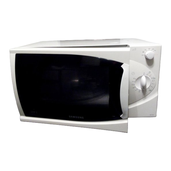
Page 6: Operating Instructions
3. Operating Instructions 3-1 Control Panel Defrost Selection 850W Instant Cook M1714 3-2 Features & External Views Door Safety Interlock Holes Light Ventilation Holes 850W Control Panel Glass Plate Roller Ring Door Latches Coupler 850W 489mm 370mm Samsung Electronics... -
Page 7: Disassembly And Reassembly
VOLTAGE TRANSFORMER secondary and filament terminals. It is extremely dangerous to work on or near these circuits with the oven energized. Screws H. V. Trans DO NOT measure the voltage in the high voltage circuit including filament voltage of magnetron. Samsung Electronics... -
Page 8: Replacement Of Door Assembly
1. Insertion depth of the thin metal plate should be 0.5mm or less. 4-3-4 Removal of Key Door & Spring Remove pin hinge from Door "E" Detach spring from Door "E" and key door. Door "E" Key Door Spring Samsung Electronics... -
Page 9: Replacement Of Fuse/Drive Motor
Base Plate 8. Connect all the leads to the drive motor. Drive Motor Cover 9. Screw the deive motor cover to the base plate with a screw driver. 10. Remount the coupler in the correct position. Samsung Electronics... - Page 10 4-6-1 Removal of Ass'y Control Box 1. Disconnect the connectors from the control box assembly. 2. Remove screws securing the control box assembly. 3.Remove the knobs of the control box Ass'y. SCREW 4. Remove the screw securing the timer. CONTROL BOX Samsung Electronics...
-
Page 11: Alignment And Adjustments
2. Isolate the magnetron from the circuit by disconnecting its leads. 3. A continuity check across the magnetron filament terminals should indicate one ohm or less. 4. A continuity check between each filament terminal and magnetron case should read open. Cooling Fins Samsung Electronics... -
Page 12: High Voltage Capacitor
Door Closed procedures. ¥ Primary switch 5. Confirm that the gap between the switch ¥ Monitor switch (COM-NC) housing and the switch actuator is no more than ¥ Monitor switch (COM-NO) 0.5mm when door is closed. ¥ Secondary S/W Samsung Electronics... - Page 13 NOTE 1: Variations or errors in the test procedure will cause a variance in the temperature rise. Additional power test should be made if temperature rise is marginal. NOTE 2: Output power in watts is computed by multiplying the temperature rise (step E) by a factor of 91 times the of centigrade temperature. Samsung Electronics...
-
Page 14: Procedure For Measurement Of Microwave Energy Leakage
; CENTRAL SERVICE CENTER 5-13-2 At least once a year have the microwave energy survey meter checked for accuracy by its manufacturer. Samsung Electronics... -
Page 15: Troubleshooting
2) Defective con- The oven lamp does not light and fan motor Replace the timer. tacts of timer does not operate. NOTE: Interlock monitor switch must be replaced when the fuse is blown out. Samsung Electronics... - Page 16 3) Too small a If a small amount of food is heated repeatedly over To increase the oven load or no a long period of time, microwave turns off during load, place a glass of load operation. water into the oven. Samsung Electronics...
-
Page 17: Unsatisfactory Cooking
1) If there is no continuity in forward, direction the H.V.Diode is open. Replace. 2) If there is continuity in reverse direction, it's shorted. Fan motor Fan motor Check if the motor coil is open. Replace. does not rotate. Samsung Electronics... -
Page 18: Exploded Views And Parts List
7. Exploded Views and Parts List 7-1 Exploded Views Samsung Electronics... -
Page 19: Main Parts List
DE59-40001A DIODE-H.V;HVR-1X-32B-12 DE91-70061B ASSY-H.V.FUSE;THV060T-0750-H,5KV0.75A,RED DE61-40017A FOOT;PP(A353),BLK,MW5630T DE31-10154A MOTOR-DRIVE;M2HJ49ZR02,ST-16,50/60HZ DE80-10003D BASE-PLATE;SGCC1-Z,T0.8,-,-,CE2713/33/CE2714/74,3RD-W DE47-20173A THERMOSTAT;PW-2N(90/60)30,187Y,250V7.5A,9 CAVITY DE71-60450B COVER-MGT;PP,T2,W110.5,L109,-,28G,3RD-0.7 DE94-00201G ASSY DOOR;M1714R/BWT,P-WHT,FISH2 ,RUSSIA DE94-00098J ASSY CONTROL-BOX;230V50HZ,M1714R/BWT,P-WHT,FISH2,RUSSIA DE73-90027A FERRITE-CORE;NI-ZN,T13.8,W21.0,L28.0,BNF-14 3601-000448 FUSE-FERRULE;250V,10A,SLOW-BLOW,CERAMIC,6.3 3601-001126 FUSE-FERRULE;250V,1.6A,QUICK-ACTING,CERAMIC DE64-40008B DOOR-C;PP,T1.5,BLK,CE745G : Warning : Option Parts :Electrostatically Sensitive Devices Samsung Electronics... -
Page 20: Door Parts List
DE64-40277B DOOR-A;ABS(HR-0370),200G,WHT(W9501),M DE64-40278K SCREEN-DOOR;ACRYL,-,-,-,SMOG,M1714R/BWT,RUSSIA DE94-00124C ASSY DOOR-SUB;M1714/1774,BLK-COATING,FISH2 DE64-40264C DOOR-KEY;POM(F20-02),5g,BLK,-,2ND HANDL DE61-70033A SPRING-KEY;ES,HSWR10,PI0.6,D6.0,L22.3,BLU DE61-80005A HINGE-UPPER;SCP1,T2.3,ZN-COATIN,M745 DE61-80004A HINGE-LOWER;SCP1,T2.3,ZN-COATING,M745 DE94-00202F ASSY DOOR-A;M1714R/BWT,P-WHT,FISH2,SUB-PART 7-4 Control-Box Parts List Ref. No. Parts No. Description / Specification Q'ty Remarks DE64-00008A KNOB-TIMER;ABS(HR0370),P-WHT,M1714 DE71-00006A COVER-PANEL;ABS(HR0370),M1714/XEF,-,-,P-WHT DE72-00010J CONTROL-PANEL;M1714R/BWT,-,-,-,-,P/WHT,RUSSIA DE64-00006A KNOB-POWER;ABS,10G,WHT,-,M1974 DE45-00004A TIMER;TMFK35M1B1,-,-,-,FISH ,-,-,CMO/VARIABLE... -
Page 21: Standard Parts List
SCREW-ASSY TAP TITE;PH,TC,M4X8,SWRCH18A,ZPC2,GLD,W CAVITY TCO DE60-10098A SCREW-ASSY TAP TITE;PH,TC,M4X8,SWRCH18A,ZPC2,GLD,W D/MOTOR DE60-10098A SCREW-ASSY TAP TITE;PH,TC,M4X8,SWRCH18A,ZPC2,GLD,W MGT TCO DE60-30016A NUT-FLANGE;M4,MSWR10 F-MOTOR DE60-10069A SCREW-TAP TH;TH,M4,L10,FRFZY RELAY DE60-10072A SCREW-TAP TH;TH,M4,L16,FEFZY,2-SLOT TIMER DE60-10069A SCREW-TAP TH;TH,M4,L10,FRFZY SCR/DOOR DE60-10098A SCREW-ASSY TAP TITE;PH,TC,M4X8,SWRCH18A,ZPC2,GLD,W H.V.D DE60-10012A SCREW-TAP TITE;TH,+,3,M4,L10,SWR10,ZPC2,TOOTH Samsung Electronics... -
Page 22: Schematic Diagrams
8. Schematic Diagrams 8-1 Schematic Diagrams Samsung Electronics...